
Fix butterfly valve open and closed position indicator mistakes by connecting each cue with the actual shaft, coupling and accepted disc reference. Keep the commanded state, local pointer, sensor feedback and physical travel separate. A remote closed label describes its configured information path; the required sealing result still needs independent acceptance evidence.
If a control screen reports closed while a slipped or misindexed connection leaves the disc elsewhere, repeating the command may not explain the disagreement. A local pointer can repeat the same error if it references the same upstream component. Record the information path and actual assembly, then investigate the mismatch through the selected manuals and authorized checks.
1. What anchors butterfly valve open and closed position indication?
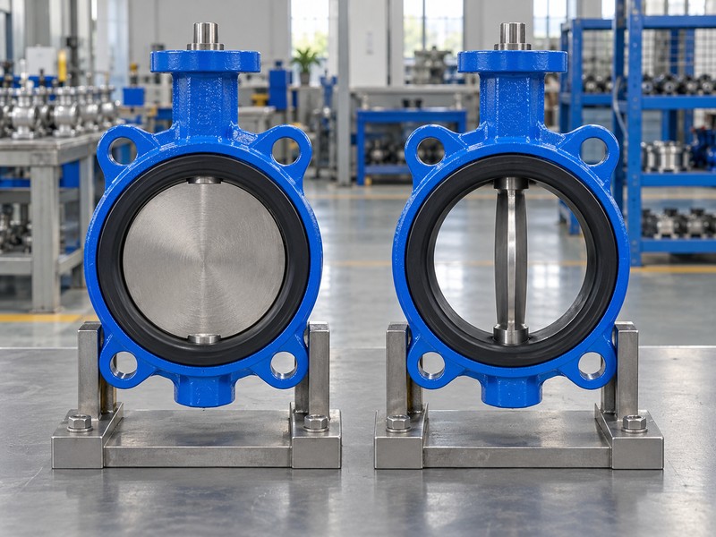
A butterfly valve open and closed position check starts from the accepted physical disc reference, with observer direction recorded. In a simplified concentric valve, the closed disc plane crosses the flow axis and the open plane lies approximately parallel to it. Your drawing establishes the actual endpoints against which a lever, pointer or feedback value must be compared.
What belongs in the indication reference map?
Identify the product, drawing revision, shaft reference and component that each indicator observes. Follow the observed movement. A pointer on an actuator and a sensor on its output may reference the same upstream part, so agreement between them cannot establish every downstream connection. Keep any physical verification within the selected instructions and authorized isolation requirements.
- Identify the physical disc endpoint and observer direction.
- Locate the component each indicator actually observes.
- Connect those references through the accepted assembly drawing.
Key takeaway: Connect indication with the physical disc reference through the documented mechanical path.
| Check | What you should confirm |
|---|---|
| Physical reference | Disc endpoint follows the actual drawing |
| Observation | Indicator location and observed component are identified |
| Connection | Accepted transmission links indication with disc movement |
2. Can a lever prove butterfly valve open and closed position?
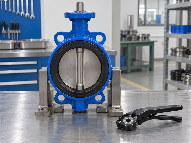
A verified lever-to-shaft relationship connects butterfly valve open and closed position indication with the actual disc. Handle direction alone cannot establish that relationship for every mounting arrangement. Check the selected lever, shaft fit, retained orientation and accepted endpoint references before interpreting a familiar parallel or perpendicular handle position as the valve’s state.
What does the detached-lever image leave unverified?
The separate components illustrate a lever and a closed concentric valve without establishing that they fit each other. Check the actual part identities. The picture cannot prove a mounting-hole match, indexing convention or permitted reassembly orientation. Use the selected drawing and instructions before approving replacement fit or indication.
- Match actual lever and shaft identities.
- Verify retained fit and accepted endpoint indexing.
- Review replacement components before accepting their indication.
Key takeaway: Interpret a lever only through its verified component fit and indexing relationship with the actual disc.
| Check | What you should confirm |
|---|---|
| Fit | Selected lever belongs to the actual shaft interface |
| Indexing | Handle reference matches the accepted disc endpoint |
| Image scope | Detached concepts do not establish compatible parts |
3. Do detents define butterfly valve open and closed position?
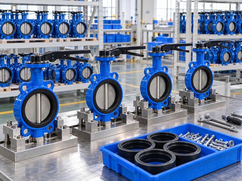
Detents can retain an operator setting, but butterfly valve open and closed position must follow the selected mounting and indexing definition. A notch count or familiar plate shape cannot establish universal endpoints, angle increments or size limits. Review the actual operator parts and their documented relationship with the disc before accepting a plate marking as a verified state.
Which assembly records should the reviewer compare?
Identify the lever, notch plate, mounting orientation and drawing revision for the actual valve. Follow the indexing reference. Compare the accepted endpoint with the retained lever setting under the selected procedure, without importing another operator’s hole pattern or detent numbering. Intermediate retention also needs its own operating scope; the presence of a latch cannot qualify continuous throttling or establish measured flow.
- Identify actual lever and notch-plate revisions.
- Compare retained settings with the accepted indexing reference.
- Keep detent count separate from flow or duty claims.
Key takeaway: Retained settings need the actual assembly and accepted endpoint references.
| Check | What you should confirm |
|---|---|
| Parts | Lever and plate match the selected assembly |
| Endpoint | Indexing follows its documented physical reference |
| Intermediate setting | Retention does not supply hydraulic qualification |
4. What links a pointer with butterfly valve open and closed position?
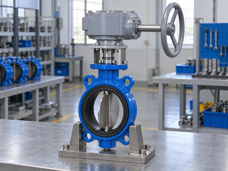
The gearbox’s output connection and indexed pointer link butterfly valve open and closed position indication with the accepted valve travel. A handwheel’s visible angle does not show the disc angle directly. Selected gearing determines input rotations, while the actual output coupling, indication and travel limits need their own documented match with the valve.
What can a pointer mismatch reveal?
Treat disagreement as a finding that needs the selected assembly records and operator instructions. Trace the output. Review pointer indexing, coupling identity and accepted disc endpoints before choosing a cause or changing a stop. Use selected documents for direction and holding properties; wheel resistance cannot prove sealing.
- Separate handwheel input from accepted shaft output.
- Match the pointer and coupling with actual assembly records.
- Investigate disagreement before changing travel limits.
Key takeaway: Use a gearbox pointer through its accepted output and indexing relationship, with handwheel movement treated separately.
| Check | What you should confirm |
|---|---|
| Transmission | Gearbox output connects with the actual valve shaft |
| Pointer | Its indexing matches the accepted endpoint reference |
| Input | Handwheel turns follow the selected gearing |
5. Does a command confirm butterfly valve open and closed position?
A butterfly valve open and closed position command identifies a requested state; verified travel needs separate evidence. Compare the requested action with supported feedback and any required physical verification. An actuator may receive a command while utility conditions, configuration or a mechanical interface prevent the intended movement, so each observation needs its own reference.
Which information should accompany a command discrepancy?
Record the command source, intended action, observed feedback and relevant supply conditions for the identified assembly. Check the selected documents. Keep local mode, remote mode and supported override functions tied to actual device information rather than presumed from an automatic-actuator label. RUITO enquiries should identify the proposed configuration and its actual supply and signal requirements.
- Record the requested action and command source.
- Compare feedback under the stated utility and mode conditions.
- Use actual device documents for supported functions.
Key takeaway: A command and a reached position answer different questions; preserve both before investigating why they disagree.
| Check | What you should confirm |
|---|---|
| Request | Command source and intended state are identified |
| Response | Feedback and observations retain their conditions |
| Scope | Mode, supply and accessory functions match selected devices |
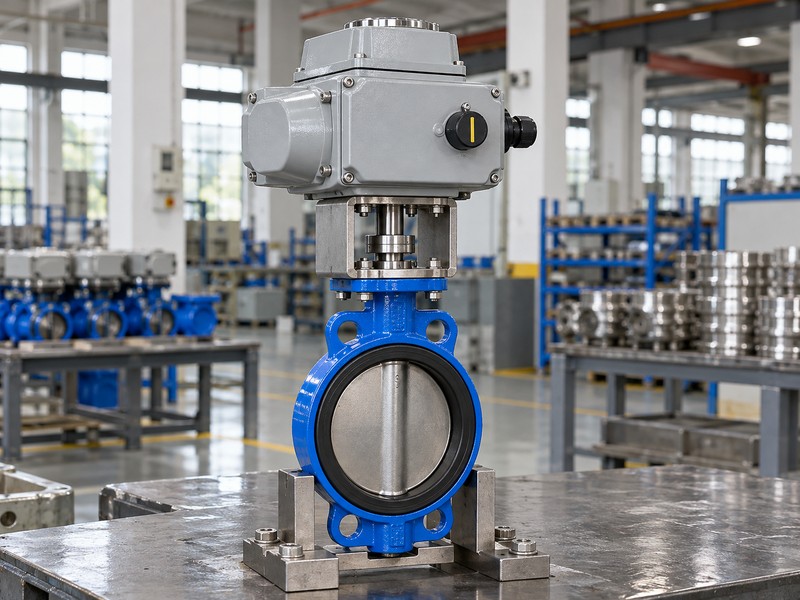
6. What feedback verifies butterfly valve open and closed position?
A butterfly valve open and closed position feedback value represents the component and movement its selected sensor observes. Identify sensor location, mechanical engagement and the configured endpoints before interpreting the value as disc position. Feedback from an actuator can agree with its pointer while an unverified downstream coupling or shaft relationship remains outside that observation.
Where should the reviewer follow the feedback path?
Trace the sensing connection through the actual mounting, coupling and shaft references. Check the measurement boundary. A travel sensor, limit switch and positioner can provide different supported information, so use each selected manual and output definition. Where positioner feedback is present, shaft travel remains distinct from measured process flow, and any flow-control claim needs its own sensor, controller and hydraulic evidence.
- Identify sensor location and the observed mechanical component.
- Verify engagement and configured endpoint references.
- Separate travel feedback from actual flow measurement.
Key takeaway: Feedback supports its actual observation point; the accepted mechanical path connects that reference with the disc.
| Check | What you should confirm |
|---|---|
| Location | Record states where the sensor observes movement |
| Connection | Accepted mechanical references support the indication |
| Function | Selected output definition governs the reported value |
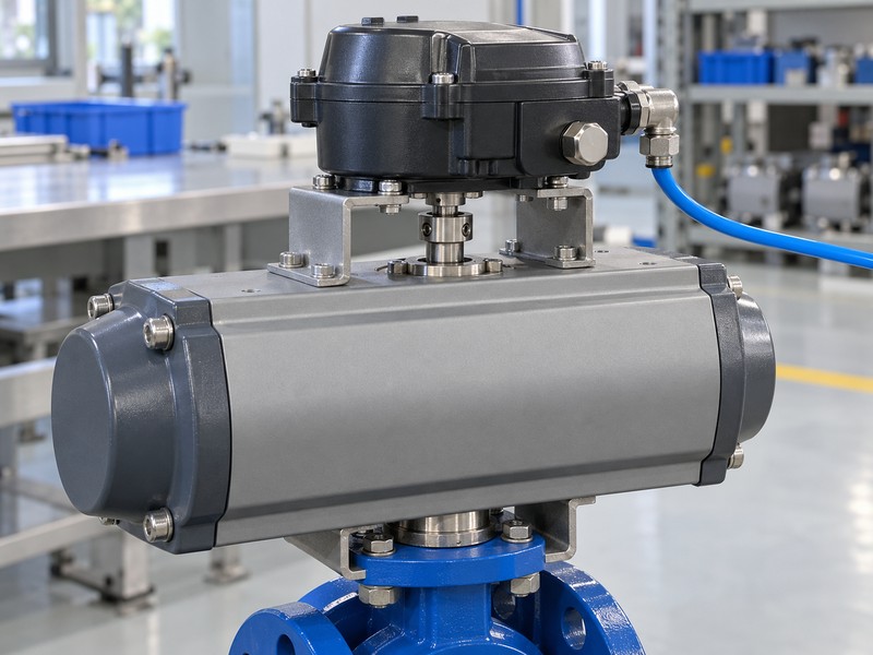
7. What maps butterfly valve open and closed position signals?
The selected input, output and endpoint mapping defines how butterfly valve open and closed position appears in signals. A current command and a feedback output perform different functions even when their ranges resemble each other. With a configured 4–20 mA input, 4 mA normally represents the low command rather than an inherent signal-failure event.
Which loss events should the configuration identify?
Review air loss, command-signal loss and electrical-power loss separately, including which other utilities remain available. Follow the actual circuit. The actuator, springs, porting and accessories determine the proposed action, and a springless double-acting unit has no universal guaranteed endpoint or indefinite hold. Any calibration or event check must follow the selected manuals and authorized isolation arrangements because adjustment routines can move the valve.
- Identify command input and feedback output separately.
- Retain the configured direction and endpoint mapping.
- Review each required utility-loss event on its own conditions.
Key takeaway: Keep signal mapping, normal commands and utility-loss behaviour within their selected configuration and evidence.
| Check | What you should confirm |
|---|---|
| Mapping | Input and output functions have defined references |
| Normal command | Low command is separate from a fault condition |
| Loss event | Actual utilities and assembly determine the required review |
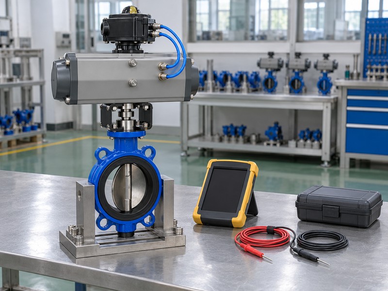
8. How do I log butterfly valve open and closed position conflicts?
Log a butterfly valve open and closed position conflict with the command, local indication, received feedback and observation conditions kept separate. Identify the unit and time associated with each record so the reviewer can compare the same event. A remote screen alone cannot diagnose whether the disagreement lies in configuration, transmission, sensing or another mechanical connection.
What makes the discrepancy useful for engineering review?
Retain the drawing revision, selected component documents, configured mode and relevant utility information with the finding. Follow the evidence path. Have qualified personnel define the permitted isolated checks before further movement, then record what was observed without choosing an unsupported cause. After authorized correction, repeat the affected verification and preserve its result with the assembly identity and accepted configuration revision.
- Keep command, local and remote observations separate.
- Link records with unit identity and observation conditions.
- Retain authorized correction and affected verification results.
Key takeaway: Retain observed facts and configuration records so engineering can investigate the actual discrepancy.
| Check | What you should confirm |
|---|---|
| Event | Records refer to the same unit and observation period |
| Finding | Observed facts remain separate from an unverified diagnosis |
| Closure | Authorized work and repeat checks have traceable results |
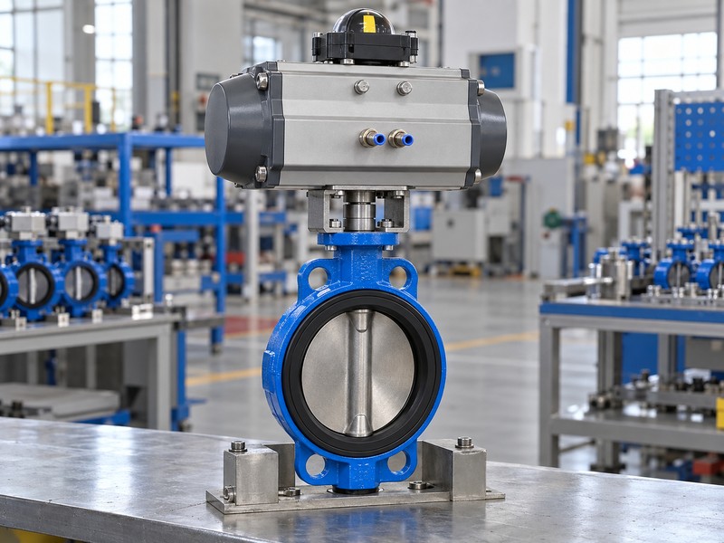
9. Does flow establish butterfly valve open and closed position?
Measured flow cannot establish butterfly valve open and closed position without the system conditions and actual valve data. A low or absent reading can involve pressure conditions or other equipment, while partial disc travel cannot establish a matching flow percentage. Keep the hydraulic observation separate from the command, indicated travel and physical endpoint records.
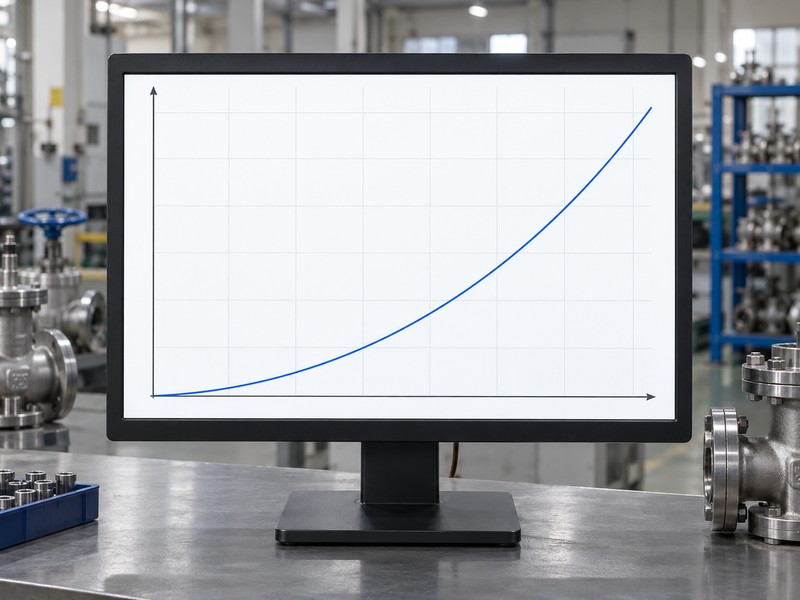
What should the conceptual liquid curve explain?
The graph uses horizontal flow and vertical pressure loss at fixed flow coefficient and liquid density. Review the actual duty. Opening-specific model data and real fluid and pressure conditions govern the applicable calculation, with gas sizing using its own inputs. A retained intermediate setting or a fitted positioner cannot qualify continuous throttling, and the open disc and shaft remain in the bore with actual pressure loss to evaluate.
- Record flow and position as separate observations.
- Use actual opening-specific coefficients and system conditions.
- Keep conceptual curves separate from measured performance claims.
Key takeaway: Flow and position need their own data, conditions and accepted reference paths.
| Check | What you should confirm |
|---|---|
| Flow | Measurement retains its actual system conditions |
| Position | Mechanical travel has an independent reference |
| Duty | Model data and accepted envelope support the calculation |
10. Does butterfly valve open and closed position prove closure?
A butterfly valve open and closed position indication cannot prove the required seat-leakage result or pressure integrity of the actual unit. Connect the accepted disc reference with its separate inspection requirements. The pressure direction and permitted closing differential also need the model’s declared rating, rather than a general assumption from the pointer, connection or available flow path.
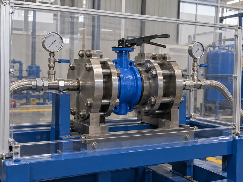
Which acceptance records should accompany the indication check?
Retain product identity, physical reference, configured indication and the agreed pressure-test evidence with their conditions. Review each result’s scope. A method such as ISO 5208 addresses its specified pressure checks and cannot establish control accuracy or increase working-pressure limits. Keep shell, shaft external-leakage and seat-closure results distinguished, with required product approvals tied to their actual configuration and destination coverage.
- Separate physical position from leakage acceptance evidence.
- Record required pressure direction and closing differential.
- Connect indication and inspection results with the supplied unit.
Key takeaway: Accept indication, sealing and pressure results against their separate evidence and conditions.
| Check | What you should confirm |
|---|---|
| Indication | Configured reference matches its accepted mechanical path |
| Sealing | Agreed result states medium, pressure, direction and criterion |
| Acceptance | Product identity and required evidence connect with the decision |
Send RUITO your assembly identification, drawing, indication details and discrepancy record. We can review the proposed configuration and identify the mechanical, signal or inspection questions that still need evidence. Contact us before accepting an unresolved position report or changing the approved assembly baseline.
FAQ
Q1: Can two matching displays prove the disc position?
No. They may observe the same upstream component; verify the documented mechanical path from each observation point to the disc.
Q2: What’s the best evidence for a suspected lever mismatch?
Use the actual component and assembly records. Retain observed indication, physical reference and the selected indexing information before any authorized correction.
Q3: How do I know what a feedback value represents?
Identify its sensor and configured output. Check location, observed component, direction and endpoint mapping against the selected device documents.
Q4: Can I treat the low current command as signal failure?
Usually no. On a configured 4–20 mA input, 4 mA normally represents the low command; verify loss-event behaviour separately.
Q5: Can a closed indication replace the seat test report?
No. The required leakage result needs its own agreed test conditions and product-specific evidence, separate from indication acceptance.