
Fix butterfly valve with positioner selection mistakes by defining the valve duty, command, measured travel, actuator and acceptance requirements as one assembly. Choose the valve for the fluid and hydraulic conditions, then confirm that the drive and positioner can position it under those conditions. Record each interface before asking suppliers to select equipment.
You ask for a modulating valve and receive an offer with a pneumatic actuator and a current-input positioner. The drawing looks complete, yet the supplier has not identified the minimum available air supply or the response to a lost command. The assembly may fit the pipe while leaving the control requirements unresolved. Use a shared selection sheet that follows the process duty through to the installed signals and failure behavior.
1. What defines a complete butterfly valve with positioner?
A complete butterfly valve with positioner has an identified valve, actuator, positioner, mounting, feedback arrangement and utility connections. The positioner compares the command with measured travel and adjusts the drive output. Define what you need the assembly to do before treating the accessory name as a complete specification for control or supply.
Which functions must your enquiry separate?
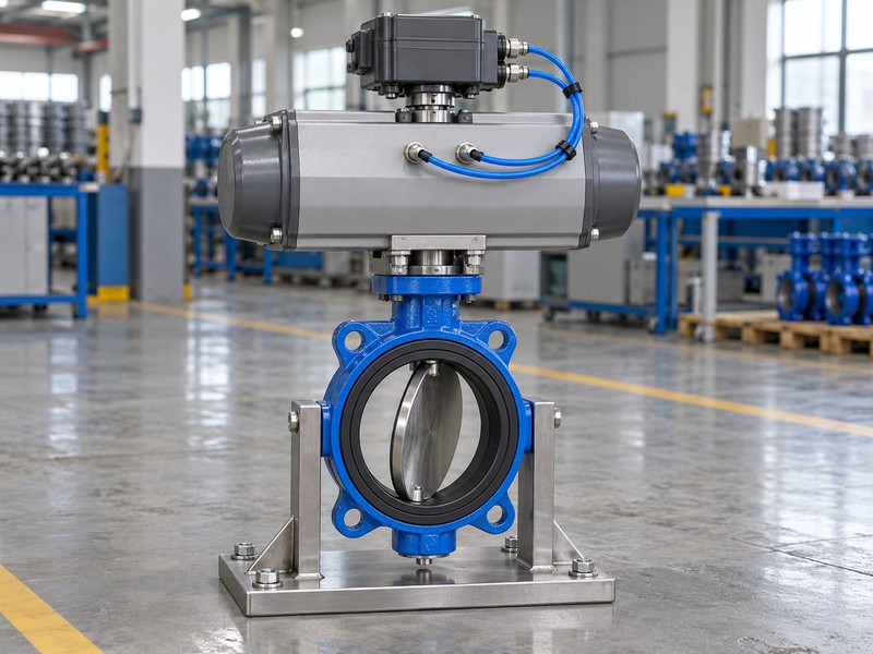
Identify whether your controller requests shaft position or uses a measured process variable to generate that request. List the valve and actuator interfaces alongside the positioner’s input, feedback and pneumatic connections. Your receiving team can then compare the equipment with a component schedule; a photograph may include options outside the quoted scope.
- Identify the valve, actuator and selected positioner separately.
- Describe the command source and required operating function.
- List mounting, feedback and utility items in the supply scope.
Key takeaway: An assembly definition lets you assess the accessory in the context of the valve, drive and control function you intend to buy.
| Check | What you should confirm |
|---|---|
| Valve | Accepted fluid duty and hydraulic configuration |
| Drive | Actuator, mounting and available energy |
| Position loop | Command, measured travel and output arrangement |
2. Which command suits a butterfly valve with positioner?
The command for a butterfly valve with positioner must match the selected positioner’s input and configured travel direction. Electrical current and pneumatic command pressure are different interfaces. A common 4–20 mA input can request position, but the low-end current does not automatically mean closed or indicate a signal fault.
What should the signal schedule identify?
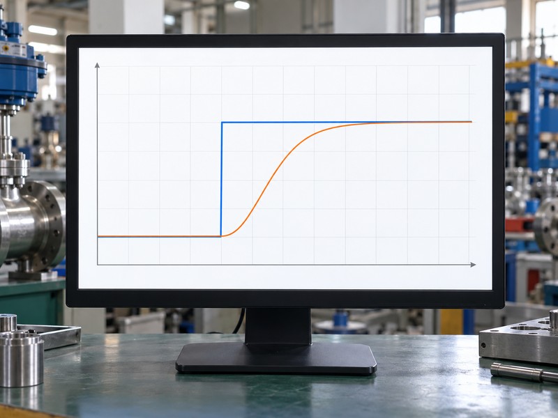
Separate the command input, any auxiliary electrical supply and an optional position-feedback output, even when two circuits use current signals. Record which input corresponds to each accepted end position and how the device detects an invalid command. The conceptual chart below concerns command and shaft travel; it supplies no measured flow curve or guaranteed response time for the proposed assembly.
- Specify input type and the configured travel direction.
- Separate command, electrical supply and feedback output circuits.
- Confirm fault detection independently of normal low-end operation.
Key takeaway: A signal range becomes useful only when you define its function, wiring and relationship to the actual valve travel.
| Check | What you should confirm |
|---|---|
| Input | The controller’s compatible command interface |
| Mapping | Accepted input values and corresponding travel |
| Output | Required position indication or feedback function |
3. Which duty limits apply to a butterfly valve with positioner?
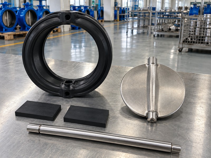
The duty limits of a butterfly valve with positioner come from the accepted valve configuration and operating conditions. Adding a positioner does not raise the body’s working rating or approve another fluid. RUITO’s ordinary clean-water duty uses 5–60°C and the selected PN10/16 pressure–temperature rating, with installation and transient conditions also reviewed.
What should you state about the fluid?
Include composition, additives, solids and cleaning fluids, then provide normal and extreme temperature, operating pressure and maximum closing differential. If your fluid or temperature requires a different seat or lining, ask for that configuration’s own acceptance basis. Keep reduced-pressure and special approval requirements visible in the enquiry; a material name cannot establish vacuum, drinking-water, fire or gas qualification for the assembled valve.
- Provide fluid composition, solids and cleaning conditions.
- State temperature, working pressure and closing differential separately.
- Request configuration-specific evidence for any special service.
Key takeaway: Select the valve against its actual exposure and duty before evaluating the positioner and actuator fitted above it.
| Check | What you should confirm |
|---|---|
| Exposure | Actual fluid and every relevant cleaning medium |
| Duty | Pressure and temperature limits applying together |
| Qualification | Evidence for the exact requested special service |
4. How do you size a butterfly valve with positioner for flow?
Size a butterfly valve with positioner for flow using the required operating cases and the selected valve’s coefficient data. Provide minimum and maximum flow, fluid properties and allowable pressure loss. A percentage of shaft travel cannot tell you the same percentage of system flow because the valve characteristic and pressure conditions affect that relationship.
Which hydraulic questions need separate approval?
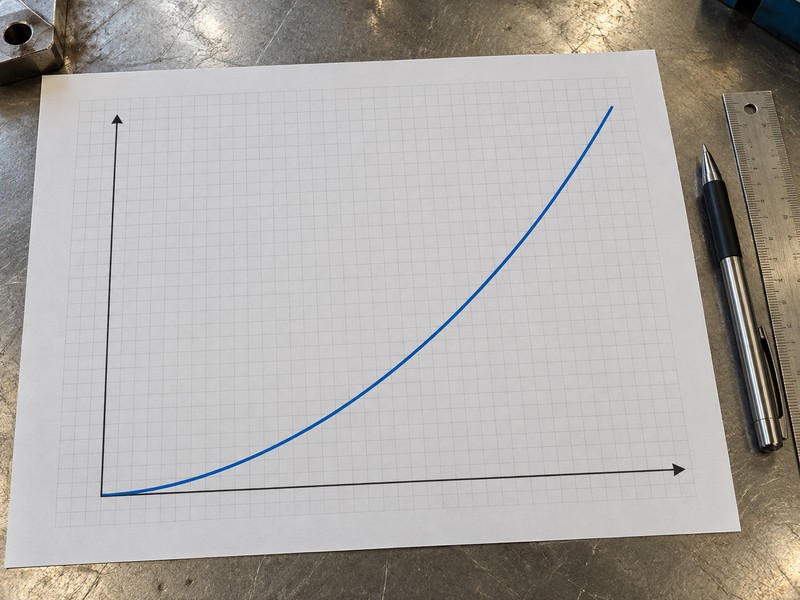
Ask for coefficient data and the permitted operating envelope for the actual DN, disc and seat configuration, then review minimum controllable flow and cavitation risk. A positioner cannot qualify an isolation valve for unrestricted continuous throttling or prevent liquid-pressure conditions that cause cavitation. The illustrative flow curve below explains a trend; obtain approved model data before you use it for selection or a contractual pressure-loss requirement.
- Declare flow extremes and the valve pressure-loss budget.
- Request model data for the intended operating positions.
- Review controllable range and cavitation separately from travel accuracy.
Key takeaway: Hydraulic selection determines whether the valve can perform the control duty; position feedback cannot replace that selection work.
| Check | What you should confirm |
|---|---|
| Inputs | Flow, density, viscosity and pressure conditions |
| Valve data | Coefficient and accepted operating-position envelope |
| System review | Minimum control range and liquid-pressure risks |
5. What air supply does a butterfly valve with positioner need?
A butterfly valve with positioner needs instrument air that meets the selected actuator and positioner manuals for pressure, quality and capacity. Declare the minimum supply available during movement as well as the upper limit. Command pressure, actuator supply pressure and process-fluid pressure serve different purposes and should appear as separate fields on your selection sheet.
How should you describe the utility interface?
Ask which filter, regulator, tubing and fittings the supplier includes, then compare their capacity and material requirements with the site’s utility specification. Air pressure measured while nothing moves may leave supply restrictions unresolved during stroking. Use the chosen device’s contamination and dryness limits; neither a familiar catalogue pressure nor another OEM project’s air supply defines what this assembly requires.
- Declare minimum available and maximum permitted supply.
- Specify the site’s air-quality and connection requirements.
- Confirm filter, regulator, tubing and fitting responsibilities.
Key takeaway: An accepted air interface gives the actuator and positioner the supply conditions used in their selection and commissioning checks.
| Check | What you should confirm |
|---|---|
| Pressure | Required supply under the expected operating demand |
| Quality | The selected manuals’ contamination and dryness limits |
| Capacity | Suitable supply path, regulator and tubing arrangement |
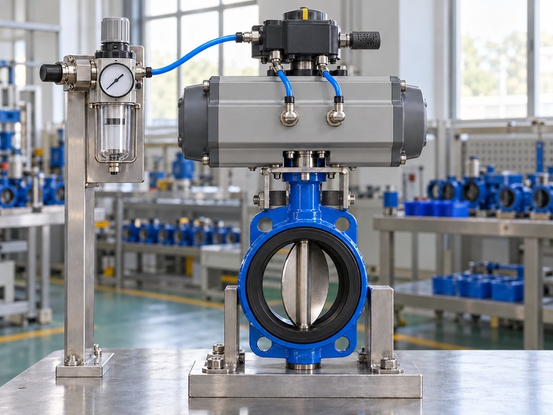
6. What torque does a butterfly valve with positioner need?
A butterfly valve with positioner needs actuator output that meets the valve’s torque demand throughout the required travel at minimum available supply. Request the actual breakaway, running and closing basis at the declared duty. For a spring-return assembly, review the return side as well as the air-powered side before approving the chosen direction.
What should the selection calculation compare?
Identify maximum closing differential, temperature, seat configuration and required operating frequency, then review the actuator’s output curve and the agreed sizing margin. Check shaft and coupling loads within the approved assembly. A positioner can meter available air, but it cannot manufacture missing drive capacity or approve extra loading caused by an incorrectly installed valve or misaligned coupling.
- Use model torque at the actual closing differential.
- Check actuator output at the declared minimum supply.
- Review return torque, coupling loads and the agreed margin.
Key takeaway: Approve the torque calculation for the complete assembly instead of inferring closing capability from the actuator size or positioner label.
| Check | What you should confirm |
|---|---|
| Demand | Valve torque across travel at the declared duty |
| Output | Available air and return output where applicable |
| Assembly loads | Accepted shaft, coupling and mounting limits |
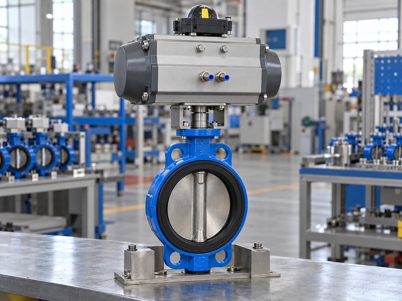
7. What feedback does a butterfly valve with positioner need?
A butterfly valve with positioner needs feedback that follows the intended shaft travel through an approved mounting and sensing arrangement. The bracket, coupling and sensor range must suit the actuator. An actuator indicator or sensor reading alone leaves the mechanical connection to the disc unresolved if the assembly has an incorrect or loose drive connection.
Which mounting details should the drawing show?
Identify the valve shaft, actuator coupling and positioner feedback connection, including their orientation and accepted travel limits. Keep actuator mounting dimensions separate from the feedback interface; a matching mounting designation does not establish every bracket or sensor fit. Request an assembled travel check that verifies direction and endpoints, then retain the approved drawing so replacement accessories use the same mechanical arrangement.
- Match bracket, coupling and sensor range to the assembly.
- Verify disc direction and accepted travel endpoints.
- Keep the approved feedback arrangement under revision control.
Key takeaway: A controlled feedback connection lets you interpret the position signal against the mechanical travel that the assembly has actually verified.
| Check | What you should confirm |
|---|---|
| Mounting | The actual bracket and actuator interfaces |
| Coupling | Correct engagement and orientation through travel |
| Feedback | Accepted sensor range and verified position relationship |
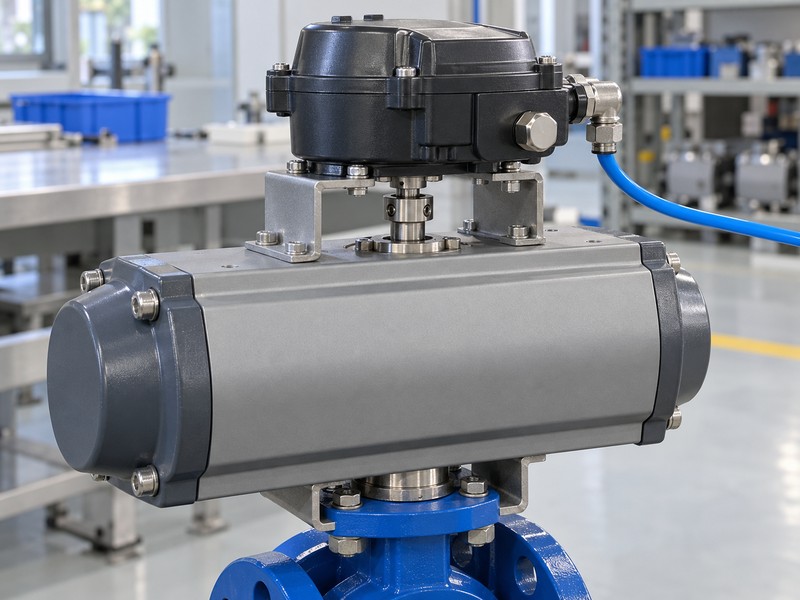
8. How should a butterfly valve with positioner fail?
A butterfly valve with positioner should respond to each failure event according to your accepted system requirement and the assembly’s verified capability. Specify air loss, command loss and electrical-power loss separately. A springless double-acting actuator has no universal assured endpoint or indefinite holding behavior, and an electrical hold function cannot establish the response to lost air.
What should the failure-event schedule contain?
Record the pneumatic variant, porting, spring action and any separately supplied solenoid, lockup device or stored-air arrangement. Ask the supplier to explain the selected device’s signal-fault settings and the evidence for the proposed response. Keep combined utility failures as their own requirement, because separate successful single-event demonstrations cannot establish performance when all drive energy is lost together.
- Define a required response for each lost utility.
- Identify remaining energy and accessory dependencies.
- Request verification for the complete selected arrangement.
Key takeaway: A failure-event schedule gives engineering and purchasing a shared basis for assessing the claimed response of the supplied assembly.
| Check | What you should confirm |
|---|---|
| Air loss | Return energy and the accepted mechanical response |
| Command loss | Enabled detection and configured fallback behavior |
| Power loss | De-energized pneumatic paths and remaining utilities |
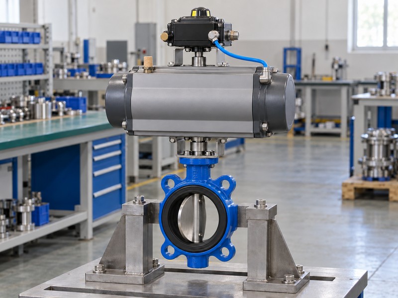
9. What scope defines a butterfly valve with positioner order?
A butterfly valve with positioner order should define every component, interface document, inspection obligation and delivery item needed for the accepted assembly. State which accessories the supplier must fit and which the site will provide. Compare priced packages only after each bidder identifies the same required operating and acceptance scope.
Which documents should purchasing request?
Include valve duty, material list, mounting drawing, torque basis, pneumatic diagram, signal schedule, selected accessory manuals and the agreed verification plan. RUITO can review configuration-specific valve inputs and the required interface documents, while your control and site teams define their system connections. List exclusions beside their requirements so an unpriced regulator, feedback option or special test remains visible during commercial review.
- Identify every selected component and supplied accessory.
- Attach accepted interface and utility documents to the order.
- Record inspection, packing and delivery inclusions explicitly.
Key takeaway: A complete order scope prevents equipment selection and commercial comparison from drifting into different definitions of the supplied package.
| Check | What you should confirm |
|---|---|
| Equipment | Defined valve, drive, positioner and accessories |
| Documents | Accepted drawings, schedules and selection basis |
| Commercial scope | Inspection and delivery responsibilities without gaps |
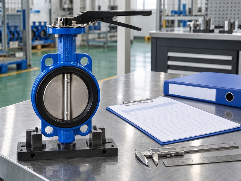
10. How do you accept a butterfly valve with positioner?
Accept a butterfly valve with positioner against separate checks for valve integrity, assembled travel, failure response and any specified process performance. A successful travel calibration establishes neither shutoff leakage nor flow-control results. Agree the test conditions and records before ordering so each acceptance claim has a defined method and an identifiable supplied assembly.
How should commissioning and valve tests differ?
A contract-selected ISO 5208 pressure test addresses valve inspection and does not calibrate the positioner or mean Class VI. Travel calibration can move the valve through its stroke, so the selected manual and authorized isolation procedure govern the work. Keep bench records, loaded checks and later process-loop acceptance identifiable, with their settings and assembly revisions recorded.
- Separate pressure, travel and process acceptance requirements.
- Plan calibration under the selected manual’s safe conditions.
- Record configuration, conditions and results for every check.
Key takeaway: Distinct acceptance records show which valve, assembly and process requirements you have verified and which still require site evidence.
| Check | What you should confirm |
|---|---|
| Valve integrity | The agreed pressure and leakage test procedure |
| Assembly function | Verified travel and separate failure-event results |
| Process performance | Defined measurement and system operating conditions |
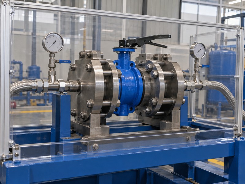
Send RUITO your fluid duty, flow cases, mating interfaces, minimum utilities and required failure responses. We can review the valve configuration and identify the documents needed to define the proposed assembly. Contact us with your selection sheet before approving a positioner package with unresolved torque, signal or acceptance requirements.
FAQ
Q1: Can I use position feedback as a flow measurement?
No. It reports travel. Flow control requires a suitable process measurement, controller and accepted valve operating envelope.
Q2: What’s the best command for my positioner?
Use the input compatible with your controller and selected device. Define the direction, supply arrangement and required output separately.
Q3: Can I assume 4 mA means signal failure?
No. It can be a valid low command. Check the configured mapping and model-specific fault-detection settings.
Q4: How do I know if the actuator is large enough?
Review model torque and available output throughout travel at minimum supply, including the return side where applicable.
Q5: Can a positioner make any butterfly valve suitable for throttling?
No. Obtain the configuration’s accepted hydraulic duty and operating positions before approving continuous intermediate-position service.