
Fix butterfly valve with pneumatic actuator and positioner package mistakes by assigning the mounting, pneumatic, electrical and acceptance interfaces to named parties before ordering. Approve one assembly drawing and component schedule. Each supplied part should match that definition, including accessories that are easy to overlook when purchasing separates the valve, actuator and controls into different orders.
Your valve supplier quotes the body and actuator, while another supplier offers a compatible positioner. During assembly, the bracket fits but the feedback connection does not follow the required rotation. Someone must now redesign the mounting and repeat the checks. Define interface ownership and the accepted component revisions early, so the package arrives with the connection details your installer needs.
1. What is a butterfly valve with pneumatic actuator and positioner?
A butterfly valve with pneumatic actuator and positioner is a valve package in which the pneumatic drive and position feedback operate through defined mechanical and control connections. The purchased scope can also include filters, regulators, tubing, switches and mounting hardware. Identify each item explicitly, because a package description alone does not establish what the supplier will deliver.
What should appear on the component schedule?
List the valve configuration, actuator action, selected positioner and fitted accessories with their document revisions. Mark customer-supplied items and identify who checks compatibility after assembly. A supplier can quote components individually, but your order still needs a complete interface definition so the installer can join them without choosing an unapproved bracket, coupling or electrical arrangement.
- List the valve, drive, positioner and every fitted accessory.
- Identify customer-supplied parts and compatibility responsibilities.
- Keep component and assembly document revisions together.
Key takeaway: A component schedule converts the package description into equipment and interface obligations that purchasing and receiving teams can check.
| Check | What you should confirm |
|---|---|
| Components | Exact valve, drive and accessory identities |
| Integration | Named responsibility for each connection |
| Order scope | Fitted, loose and customer-supplied items |
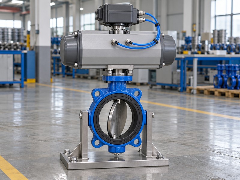
2. Can a butterfly valve with pneumatic actuator and positioner fit?
A butterfly valve with pneumatic actuator and positioner can fit when the approved valve and operator envelope match the actual pipework and available space. Check mating flanges, disc clearance and access to the positioner. A matching nominal size leaves bore restrictions, operator height and maintenance reach unresolved until you compare the assembled drawing with the site.
Which pipe-interface checks belong in the order?
Confirm flange standard, facing, bore, face-to-face dimensions and the specified gasket and fastener arrangement. If a lug package will serve a disconnected pipe end, require the special clean-water configuration: DN50–200, 5–40°C, declared closing differential no greater than 10 bar and independent end-service verification. The body shape and normal pressure marking cannot approve that maintenance condition.
- Compare flange and bore details with the supplied valve.
- Reserve operator, tubing and maintenance access in the layout.
- Review any requested lug end service as a separate qualification.
Key takeaway: Approve fit for the complete package, including operating and maintenance space, before treating a valve size as installation evidence.
| Check | What you should confirm |
|---|---|
| Pipe fit | Approved flange, facing and face-to-face dimensions |
| Clearance | Disc travel and assembled operator envelope |
| Maintenance | Access and independently accepted end-service conditions |
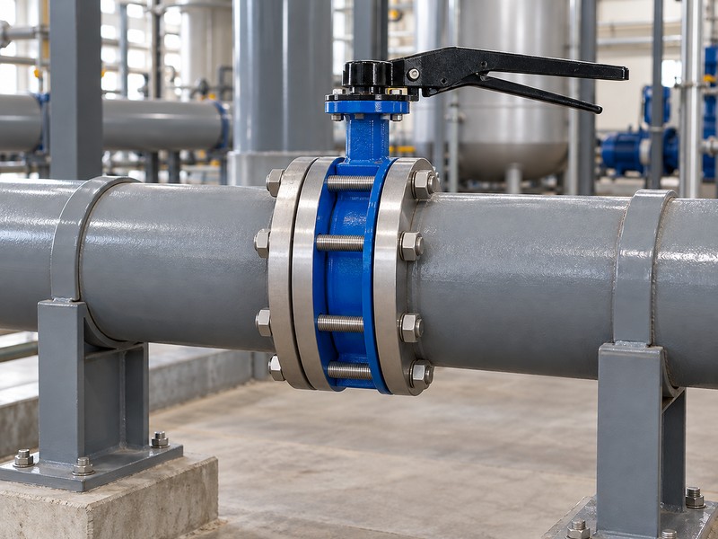
3. Who fits a butterfly valve with pneumatic actuator and positioner?
The approved assembler should fit a butterfly valve with pneumatic actuator and positioner using the accepted bracket, couplings and mounting instructions. Assign that responsibility in the purchase scope. A bolt pattern can match while the shaft engagement or feedback geometry differs, so require review of the complete motion path before the assembler energizes the package.
How should the mounting drawing define motion?
Identify actuator-to-valve engagement, bracket orientation, feedback coupling and the sensor’s accepted travel range. Keep the actuator mounting interface separate from the positioner mounting and feedback requirements. Ask the assembler to verify direction and endpoints with the actual supplied parts; a generic mounting designation cannot approve an adapter, eliminate coupling play or demonstrate correct disc movement.
- Define valve-shaft engagement and bracket orientation.
- Match feedback coupling and sensor range to actual travel.
- Assign the assembled direction and endpoint checks.
Key takeaway: One approved mounting drawing gives the assembler a defined motion path and gives you a basis for rejecting unverified substitutions.
| Check | What you should confirm |
|---|---|
| Valve drive | Correct engagement and accepted rotational direction |
| Positioner fit | Suitable bracket, coupling and sensing geometry |
| Assembly check | Verified motion with the delivered components |
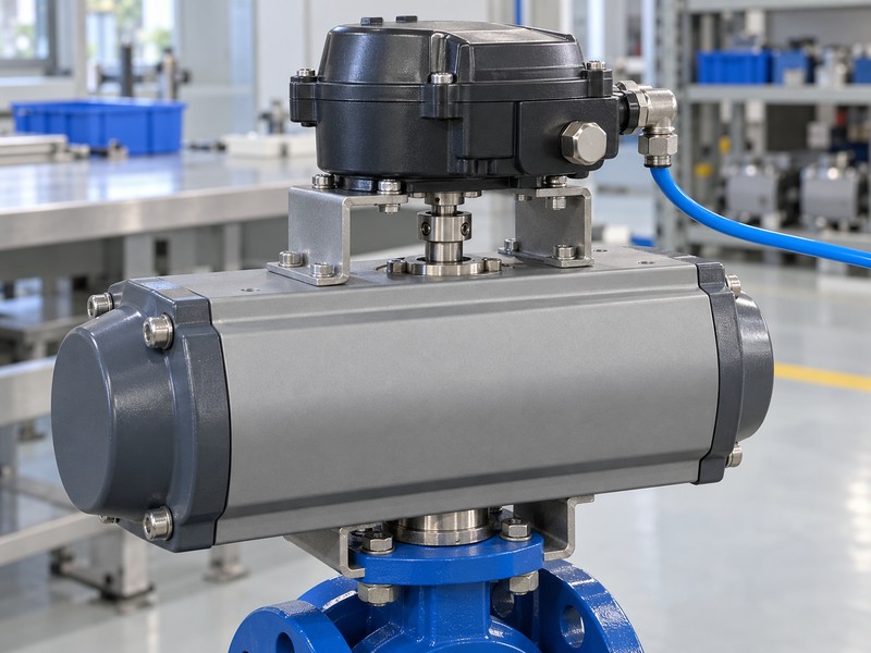
4. Who wires a butterfly valve with pneumatic actuator and positioner?
A qualified person should wire a butterfly valve with pneumatic actuator and positioner from the approved signal schedule and selected device manuals. Identify the command input, electrical supply and position output as separate functions. Do not infer terminal roles or supply requirements because the device uses a familiar current range or another project used similar accessories.
What should controls and purchasing agree?
Record signal type, configured direction, terminal assignments and any feedback or limit-switch option included in the package. Confirm which party provides cabling, glands and site connection work under the applicable requirements. Where the normal low command is 4 mA, keep that operating point separate from the device’s signal-loss detection; the complete wiring and configuration determine how the assembly responds.
- Separate command, auxiliary supply and position-output circuits.
- Specify feedback options and cable connection responsibilities.
- Approve terminal assignments and input-to-travel direction.
Key takeaway: A signal schedule prevents controls and purchasing from assigning different functions to the same quoted accessory or terminal connection.
| Check | What you should confirm |
|---|---|
| Command | Compatible input and configured operating direction |
| Electrical supply | The actual device’s required power arrangement |
| Feedback | Purchased output function and receiving-system interface |
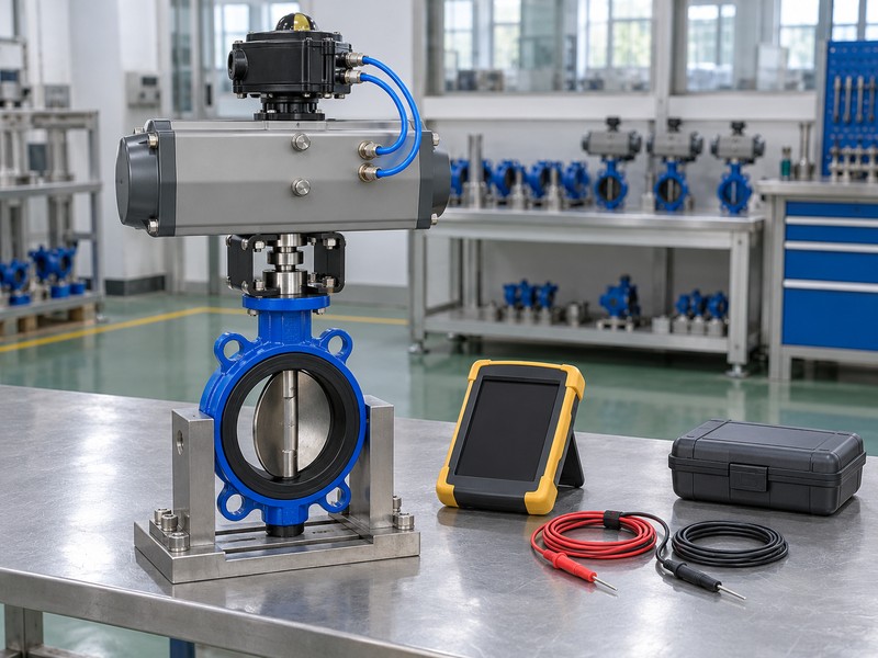
5. Who feeds a butterfly valve with pneumatic actuator and positioner?
The assigned utility provider should feed a butterfly valve with pneumatic actuator and positioner with its accepted air and electrical supplies. Define the supply at the package boundary and assign the filter, regulator and tubing scope. A static utility reading does not settle whether the supply path can support the required valve movement.
How do you define the pneumatic boundary?
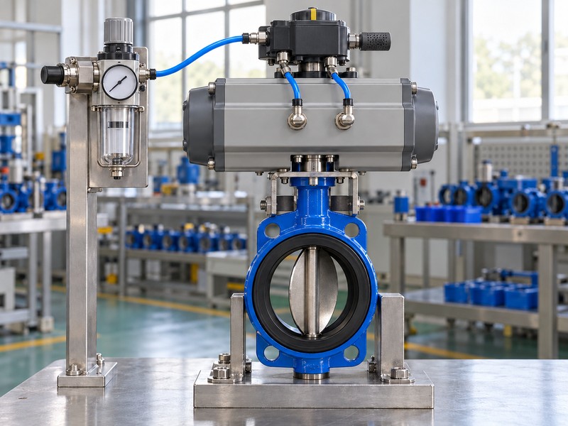
Show the accepted pneumatic paths, including any separately specified solenoid or lockup accessory, on the assembly diagram. Ask for minimum available pressure during movement, the permitted maximum and the selected manuals’ air-quality requirements. Keep actuator air separate from the process fluid and from a pneumatic command signal, then confirm who supplies the regulator and establishes its accepted setting.
- Show supply, working ports and required accessories on the diagram.
- Declare minimum available pressure and permitted maximum.
- Assign air-treatment equipment, tubing and adjustment responsibilities.
Key takeaway: A defined pneumatic boundary lets the site provide the utility conditions used to select and check the complete package.
| Check | What you should confirm |
|---|---|
| Boundary | The package supply connection and supplied equipment |
| Air path | Accepted porting, tubing and accessory arrangement |
| Utility limits | Required quality, pressure and available capacity |
6. Is a butterfly valve with pneumatic actuator and positioner sized?
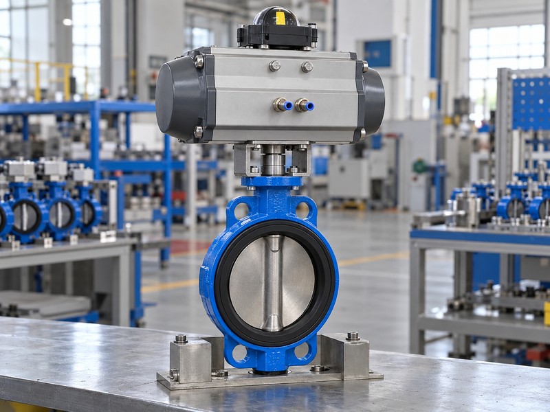
A butterfly valve with pneumatic actuator and positioner is sized only after engineering accepts the valve duty and drive output for the actual operating cases. Confirm maximum closing differential and minimum available air. Fitting a positioner does not increase the valve’s working rating, create missing actuator torque or establish suitability for unrestricted intermediate-position operation.
Which calculations should follow the package revision?
Compare the valve’s breakaway, running and closing torque with available actuator output throughout travel, including the spring side when fitted. Keep hydraulic capacity and permitted operating positions in the valve selection record, with actual coefficient data where required. A change to seat, actuator, coupling or supply conditions needs review against those records before you accept the revised package as equivalent.
- Match valve demand with output at minimum available supply.
- Review return torque and drive-component loads where applicable.
- Recheck selection when materials, drive or duty conditions change.
Key takeaway: Keep torque and valve selection tied to the package revision so later accessory or material changes cannot bypass engineering acceptance.
| Check | What you should confirm |
|---|---|
| Valve duty | Accepted exposure, hydraulic scope and differential |
| Drive output | Available torque across the actual travel |
| Revision | A selection basis matching the delivered assembly |
7. Can a butterfly valve with pneumatic actuator and positioner fail?
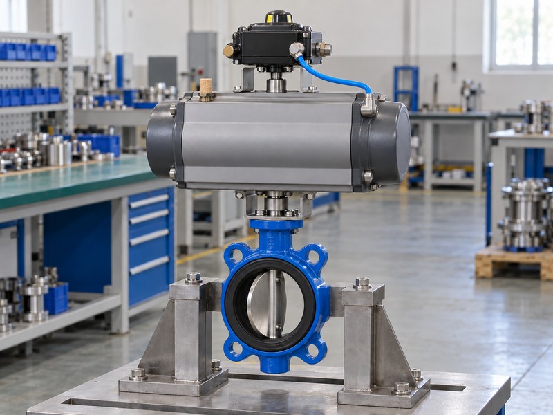
Yes, a butterfly valve with pneumatic actuator and positioner can face air, command or electrical-power loss, so specify a response for each event. The selected actuator action and pneumatic arrangement determine what the assembly can do. A springless double-acting package has no universal assured endpoint or indefinite holding response when drive air disappears.
Who verifies the required failure behavior?
Identify the remaining utilities, actuator return arrangement, positioner settings and any separate accessory on which the proposed action depends. Electrical output blocking and signal-fault fallback are different functions from response to air loss. Ask for records linked to the selected assembly, and include combined failures when the project requires them rather than assuming separate utility-loss results can be combined.
- Define air-loss, command-loss and power-loss requirements separately.
- Identify accessory dependencies and remaining stored energy.
- Assign verification and record delivery for each event.
Key takeaway: A written event schedule makes the proposed failure response part of package acceptance instead of an undefined promise attached to the actuator.
| Check | What you should confirm |
|---|---|
| Air event | Available return energy and accepted final behavior |
| Signal event | Enabled detection and actual fallback settings |
| Electrical event | De-energized porting and remaining pneumatic supply |
8. Who tests a butterfly valve with pneumatic actuator and positioner?
The party named in the inspection plan should test a butterfly valve with pneumatic actuator and positioner against the agreed package requirements. Define the buyer’s witness and review points before award. An assembled travel check can verify motion and feedback, while valve leakage acceptance and later process-loop performance require their own specified methods and conditions.
What should the integration record show?
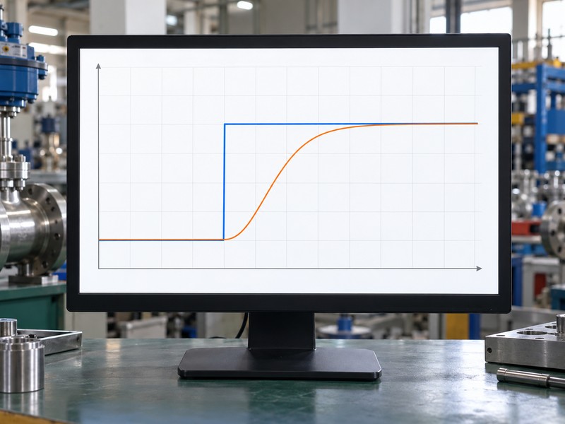
Include component identities, mounting revision, utility conditions, input direction, travel results and the separately verified failure events. The conceptual response chart below illustrates command and shaft position; request actual records for the delivered package. Calibration can move the valve, so the selected manual and authorized isolation procedure govern testing, with personnel clear of the energized mechanism throughout the check.
- Link test records to the actual component and drawing revisions.
- Verify travel, feedback direction and required failure events.
- Keep valve integrity and process performance as separate acceptance items.
Key takeaway: An agreed inspection plan tells your team what the package supplier has verified and which requirements still need site acceptance.
| Check | What you should confirm |
|---|---|
| Identity | The supplied components and accepted assembly revision |
| Function | Recorded command, travel and feedback behavior |
| Acceptance | Distinct valve, package and site test obligations |
9. Who packs a butterfly valve with pneumatic actuator and positioner?
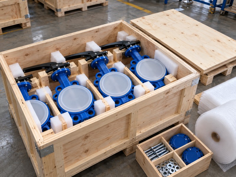
The supplier identified in the delivery scope should pack a butterfly valve with pneumatic actuator and positioner to protect its accepted interfaces and supplied accessories. List loose items separately from fitted components. Receiving should be able to match each package and document to the order line without guessing which tubing kit, coupling or manual belongs to the assembly.
What should receiving check before installation?
Ask for assembly identification, a packing list, loose-accessory labels, applicable preservation instructions and the accepted document package. Check for transport damage to brackets, tubing, connections and protective covers before releasing equipment to the installer. Record any missing component against the agreed supply split, then resolve the discrepancy before commissioning rather than substituting a locally available item without compatibility review.
- Identify fitted and loose items by assembly and order line.
- Protect exposed connections and mechanical feedback components.
- Record missing parts or damage before installation release.
Key takeaway: A controlled delivery inventory preserves the package definition between the assembly workshop, transport crate and site installation team.
| Check | What you should confirm |
|---|---|
| Inventory | The full agreed component and accessory list |
| Condition | Protected interfaces without unresolved transport damage |
| Documents | Accepted instructions and configuration records |
10. Why buy a butterfly valve with pneumatic actuator and positioner?
Buy a butterfly valve with pneumatic actuator and positioner when you need one accepted assembly definition and clear responsibility for integration. The package should still fit your fluid duty, utilities and control interfaces. Purchasing the complete combination helps only when the order records who supplies, checks and documents every required connection and acceptance item.
How do you preserve the approved package?
Attach accepted drawings, materials, signal and pneumatic schedules, selection records, inspection obligations and delivery responsibilities to the order. Require approval before substitutions to the seat, drive, positioner or feedback arrangement, including repeat supply. RUITO can review valve and interface inputs; your team should retain the accepted package records so future enquiries and site maintenance start from the actual supplied assembly.
- Close integration deviations before commercial approval.
- Attach accepted revisions and named supply responsibilities.
- Control changes to the complete package on repeat orders.
Key takeaway: A complete package earns its purchasing value through a controlled integration scope that continues into delivery and future replacement orders.
| Check | What you should confirm |
|---|---|
| Award | Closed technical exceptions and complete purchased scope |
| Acknowledgement | The same assembly and acceptance obligations |
| Repeat supply | Approved changes with revised configuration records |
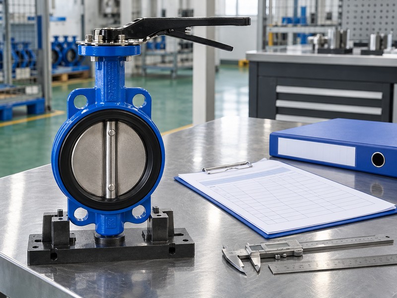
Send RUITO the valve duty, flange and mounting details, utility limits, signal schedule and required failure-event checks. We can review the proposed valve configuration and help define the documents needed for package approval. Contact us before separating component orders or accepting a substitution with unresolved integration responsibilities.
FAQ
Q1: Can I buy the positioner separately from the valve package?
Yes. Assign mounting, compatibility and assembled verification to a named party, using approved interface documents.
Q2: How do I know if a mounting adapter is acceptable?
Review its approved drawing and motion checks. A matching bolt pattern alone does not verify shaft engagement or feedback geometry.
Q3: Can I assume all accessories are included in a package quote?
No. Request a component schedule that identifies fitted, loose and customer-supplied items with any priced exclusions.
Q4: What’s the best way to handle a replacement positioner?
Use accepted records to review mechanical fit, signals and required recalibration before approving the substitute.
Q5: Can I release the package after a travel test alone?
No. Complete the agreed valve, integration, failure-event and document checks, with later site requirements identified separately.