
Fix fitting mistakes with a dn80 flanged butterfly valve by checking its condition, preparing the isolated pipeline, following the valve’s assembly instructions, and recording fit and function before handover. A correct purchase specification still needs careful site work. The approved drawing, installation manual, and system procedure should describe the same valve and service.
A replacement reaches a crowded plant room with its flange protection loose and the shutdown window already booked. Installing it immediately can conceal transport damage or debris until the line starts leaking. Follow a receiving-to-handover sequence that gives the installer, commissioning technician, and operator clear checks before responsibility passes between them.
1. What receiving checks does a dn80 flanged butterfly valve need?
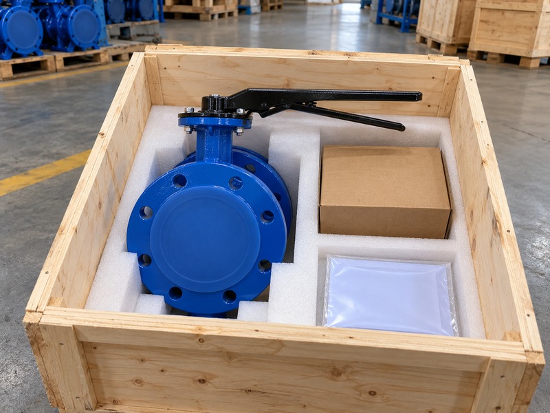
Accept a dn80 flanged butterfly valve for installation only after its identity, visible condition, and required documents match the order. Check the valve, operator, accessories, and loose hardware before discarding the packaging. Photographs taken during unpacking can help distinguish delivery damage from damage that occurs later during storage or installation.
Which receiving defects need a hold point?
Inspect the protected surfaces for impact marks, missing covers, damaged coating, displaced seat lips, bent controls, and debris. Check that the installation instructions cover the delivered operator and body construction. If a crate has shifted or the valve has fallen, hold it for the supplier’s assessment rather than accepting smooth handle movement as proof of fitness. Record the condition, identifier, photographs, and disposition before releasing the valve from receiving inspection.
Key takeaway: Receiving acceptance gives the installer a known starting condition.
- Match identifiers and accessories with the approved supply record.
- Hold damaged or uncertain assemblies for documented review.
| Item | Review |
|---|---|
| Identity | Valve, operator, drawing, and order agree |
| Condition | Protected faces and accepted damage assessment |
2. How do you prepare the pipeline for safe installation?
Prepare the pipeline for a dn80 flanged butterfly valve through the site’s approved isolation, depressurization, draining, and work-permit procedure. Qualified personnel must verify the required safe condition before opening a joint. Trapped liquid, actuator energy, automatic controls, and connected equipment can remain hazardous even when a local pressure indicator reads zero.
What must the work package establish?
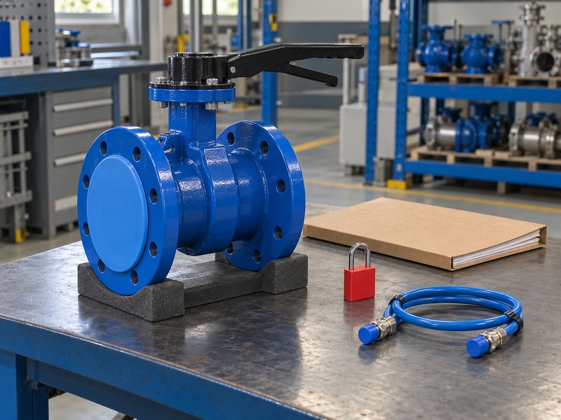
Define the isolation boundary with the system operator, including pressure sources, drains, vents, stored mechanical energy, and electrical or pneumatic connections. The plant procedure establishes how personnel may work on that system. Do not use an end-of-line statement for a lug butterfly valve as permission to open piping around another construction or change the site’s isolation method. Keep the permit status and work boundaries available to the crew handling the disconnected joint and nearby equipment.
Key takeaway: A product installation guide works within the plant’s controlled maintenance procedure.
- Have authorized personnel verify the approved isolation conditions.
- Identify trapped pressure and operator energy within the work boundary.
| Item | Review |
|---|---|
| System control | Approved isolation and verified work condition |
| Product control | Instructions for the exact delivered assembly |
3. How should you lift and support the assembly?
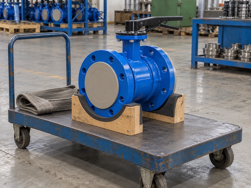
Lift and support a dn80 flanged butterfly valve using the approved handling points and a method suitable for its actual weight and operator. Protect the stem, lever, gearbox, and accessories from lifting loads. Support the pipework independently so the valve and its fasteners do not become tools for carrying or repositioning an unsupported pipe section.
Which handling shortcuts can damage the valve?
Plan where the load will rest before unpacking the valve or disconnecting temporary support. A heavy operator can shift the center of gravity, while nearby pipework may restrict sling placement. Follow the supplier’s instructions rather than lifting by a handle, shaft, accessory bracket, or an assumed lifting eye. A wafer butterfly valve handling plan cannot establish the weight, attachment points, or support requirements of the double-flanged assembly being installed.
Key takeaway: Controlled handling protects alignment and keeps weight off vulnerable valve parts.
- Check the assembly weight and permitted handling points.
- Maintain valve and pipe support throughout joint assembly.
| Item | Review |
|---|---|
| Handling | Approved lifting method and protected operator |
| Support | Stable valve position and independently supported pipework |
4. What cleaning should happen before the valve goes in?
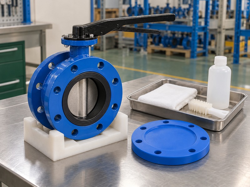
Clean the exposed joint and pipework before inserting a dn80 flanged butterfly valve, following the approved cleaning method for its seat and service. Remove loose scale, welding debris, old gasket residue, and foreign objects that could reach the disc or seat. Keep the accepted valve protected while nearby cutting, grinding, or other contamination-producing work continues.
How do you protect the seat during preparation?
Clean the pipe before exposing the sealing surfaces and inspect flange faces without scratching their finish. Use agents compatible with the seat, coating, fluid, and hygiene requirements; a site solvent may be unsuitable for a particular elastomer. Keep the valve clear of welding heat and spatter, following the approved joining sequence rather than using it as a welding alignment fixture. Fit suitable temporary protection if the cleaned system must remain open and record the final cleanliness check before assembly.
Key takeaway: Cleaning before insertion keeps installation debris away from the sealing contact.
- Remove debris without damaging faces, coatings, or seat lips.
- Confirm cleaning-agent compatibility and protect the cleaned opening.
| Item | Review |
|---|---|
| Pipe preparation | Loose debris and old sealing residue removed |
| Valve protection | Compatible cleaning and protected sealing surfaces |
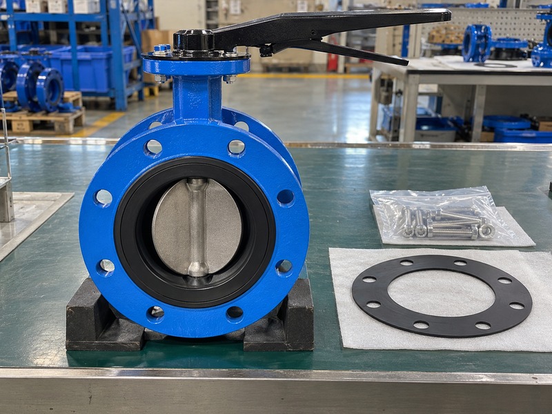
5. How do you position the body and flange seals?
Position a dn80 flanged butterfly valve with its pipe joints aligned and its disc in the installation position specified by the manufacturer. Confirm the approved orientation and sealing arrangement before bringing the faces together. RUITO’s DN80 double-flanged option uses a centerline soft-seat construction, so instructions for a different seat or offset arrangement cannot be substituted.
When should you add a separate gasket?
Follow the specified flange-sealing arrangement because some resilient seats seal at the mating flange while other constructions require separate gaskets. A PTFE-lined butterfly valve may require different flange-face treatment and compression from the rubber-seated assembly being installed. Keep approved gaskets centered and outside the disc envelope, aligning the supported pipework without using bolts to move a displaced spool. If the faces do not meet as specified, resolve the cause before compressing the seat or gasket.
Key takeaway: Correct positioning preserves both the pipe alignment and the intended seal compression.
- Use the model-specific disc position and permitted orientation.
- Confirm integral sealing or the exact required separate gasket.
| Item | Review |
|---|---|
| Position | Aligned body and approved disc installation position |
| Seals | Specified arrangement with a clear disc opening |
6. How should the installer tighten the flange fasteners?
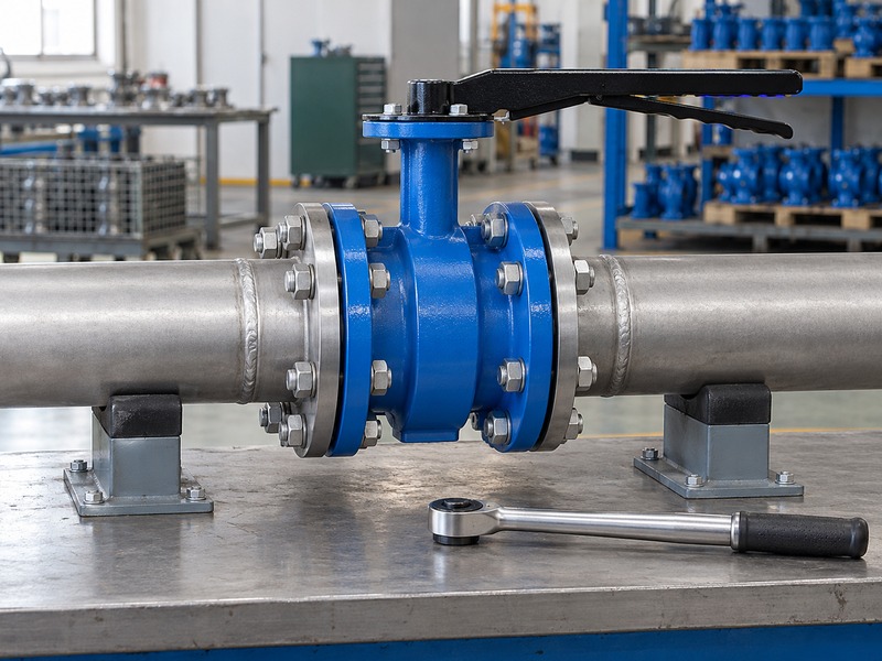
Tighten the flange fasteners on a dn80 flanged butterfly valve using the approved joint procedure, sequence, and values for that assembly. Verify the specified hardware and engagement before loading the joint. Use staged, balanced tightening where required by the procedure, and keep the valve supported as the faces settle into their intended position.
What should you do if tightening becomes uneven?
Investigate an uneven joint if the body shifts, a gap closes asymmetrically, or resistance changes unexpectedly during tightening. Recheck alignment, gasket position, contact surfaces, fastener length, and seat arrangement under the required safe conditions. Avoid borrowing torque figures from same-size valves or loading one side harder to correct misalignment; lubrication, fastener grade, gasket construction, and flange details affect the procedure. Record the accepted tightening method and completion status on the installation sheet.
Key takeaway: A documented tightening procedure avoids guesswork about bolt load and seat compression.
- Use the specified hardware, engagement, sequence, and tightening values.
- Stop for unexpected movement or uneven joint closure.
| Item | Review |
|---|---|
| Before loading | Accepted hardware and aligned joint |
| During loading | Controlled stages and balanced joint closure |
7. When should you check that the disc turns freely?
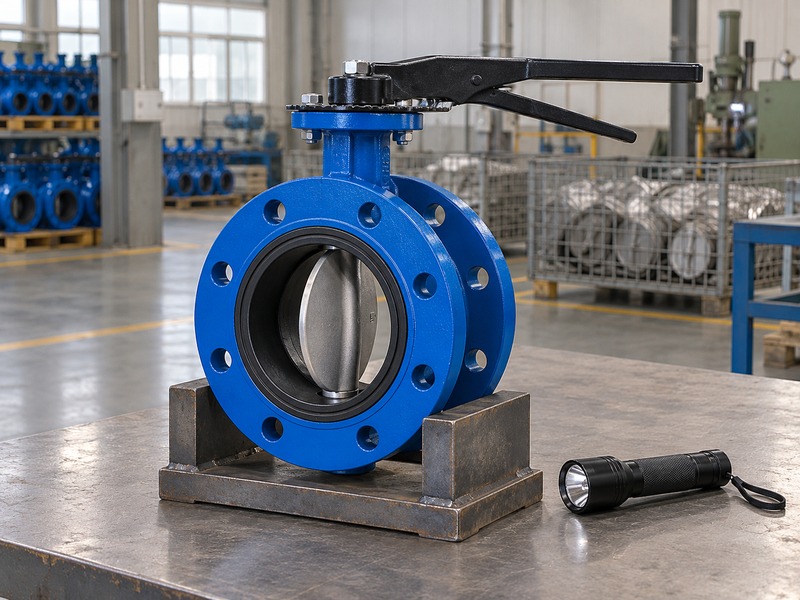
Check free disc travel on a dn80 flanged butterfly valve at the stages required by its installation instructions, including after the joint is correctly tightened. Perform these checks with the system in its approved safe condition. A valve that moved freely before installation can bind after gasket displacement, pipe misalignment, or excessive joint compression.
How do you respond to binding during a travel check?
Find the interference before adding force and compare resistance with the selected valve’s expected seat contact and operating behavior. Keep hands and tools outside the disc path while investigating the joint, internal projections, operator connection, and stops under the approved procedure. A butterfly valve dry-travel check can reveal obstruction but cannot establish closure leakage performance under service pressure. Avoid increasing operator size or altering stops to force a binding assembly through its travel.
Key takeaway: Dry cycling verifies movement while pressure acceptance requires its own procedure.
- Check travel after assembly without bypassing the safe work conditions.
- Investigate new resistance before altering stops or operating force.
| Item | Review |
|---|---|
| Travel check | Permitted movement without unintended interference |
| Separate check | Closure performance under its agreed test conditions |
8. How do you confirm manual access and position indication?
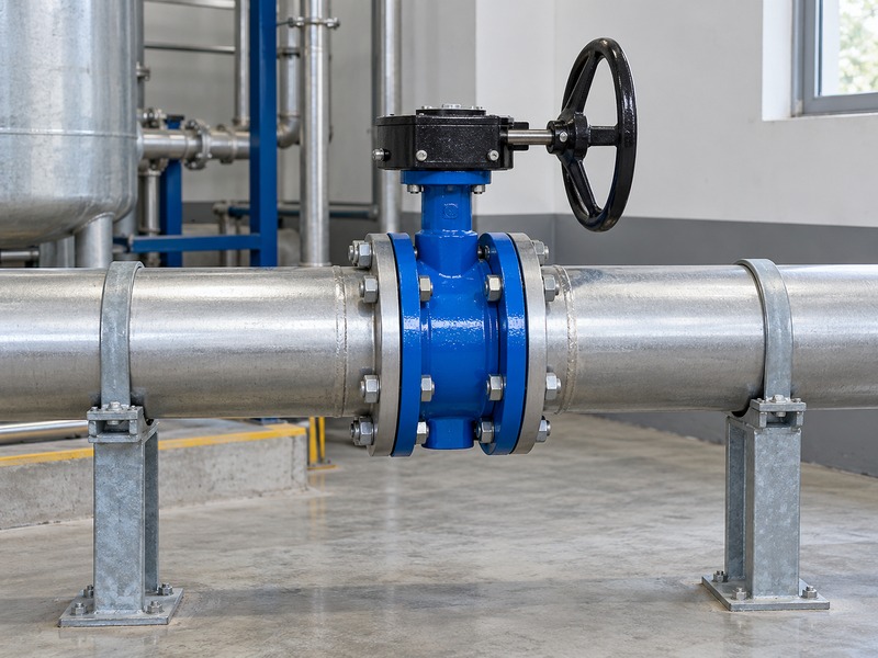
Confirm manual access on a dn80 flanged butterfly valve by checking the operator’s full movement, hand space, locking arrangement, and maintenance access in the installed location. Include the final insulation and neighboring equipment in this review. Position indication must agree with actual disc travel before the installation team hands the valve over for service.
What changes need another operator check?
Recheck the operator after any mounting change because rotating a lever, replacing a coupling, or fitting a gearbox can alter indication and stops. Follow the approved engagement, fastening, and travel-adjustment instructions rather than judging closure from the handle alone. Qualified technicians must verify actuated controls, supply conditions, accessories, and failure action under the commissioning procedure. Keep operating and maintenance access clear after nearby guards, cable trays, and insulation are fitted.
Key takeaway: An accepted operator must both show the right position and remain accessible.
- Check actual disc position against the operator’s indication.
- Repeat access checks after surrounding installation work is complete.
| Item | Review |
|---|---|
| Manual operation | Usable movement, grip space, and locking access |
| Indication | Correct engagement, indexing, and travel limits |
9. How should the team commission the installed valve?
Commission a dn80 flanged butterfly valve through the approved system procedure with qualified personnel controlling filling, venting, pressure changes, and valve operation. Confirm installation acceptance and the permitted service conditions before introducing fluid. Factory pressure-test results support product acceptance, while the site’s commissioning checks address the completed piping system and its operating controls.
Which commissioning observations belong in the record?
Record conditions beside each observation of leakage, unusual movement, vibration, position response, or operating faults. Use the agreed medium, pressure limits, sequence, hold points, and acceptance criteria rather than creating an improvised closed-valve pressure test. Confirm the approved test direction and arrangement when checking isolation or closure; two body flanges do not establish unsupported-end capability. If a fault appears, return the system to its required safe condition before qualified personnel inspect or adjust the joint.
Key takeaway: Commissioning acceptance depends on defined conditions and documented responses to faults.
- Use the authorized commissioning sequence and acceptance criteria.
- Record conditions and resolve faults before operational release.
| Item | Review |
|---|---|
| Before fluid | Installation accepted and service limits confirmed |
| During commissioning | Controlled sequence and recorded observations |

10. What records should you hand to the operating team?
Hand over a dn80 flanged butterfly valve with records linking the installed identifier to its accepted configuration, inspections, commissioning results, and maintenance instructions. Include any approved changes made during site work. The operating team needs the final arrangement and remaining restrictions so it can operate the valve and order correct replacement parts later.
How do you close the installation file?
Make the final record match the installed assembly with the final drawing, operator arrangement, material details, and accepted site deviations. Attach receiving inspection, assembly completion, travel checks, applicable test reports, commissioning acceptance, and the installation and maintenance manual. RUITO supplies configuration-specific drawings, material information, operating data, and inspection records; agree the required package for the order. Record who accepted outstanding restrictions and hold unresolved defects from operational release until the responsible authority approves their disposition.
Key takeaway: A traceable handover preserves installation decisions for later maintenance and replacement.
- Link final records and spare-parts details with the installed identifier.
- Close or formally accept deviations before responsibility changes.
| Item | Review |
|---|---|
| Installed record | Final drawing, identifier, and accepted deviations |
| Operating file | Commissioning results, instructions, and parts information |
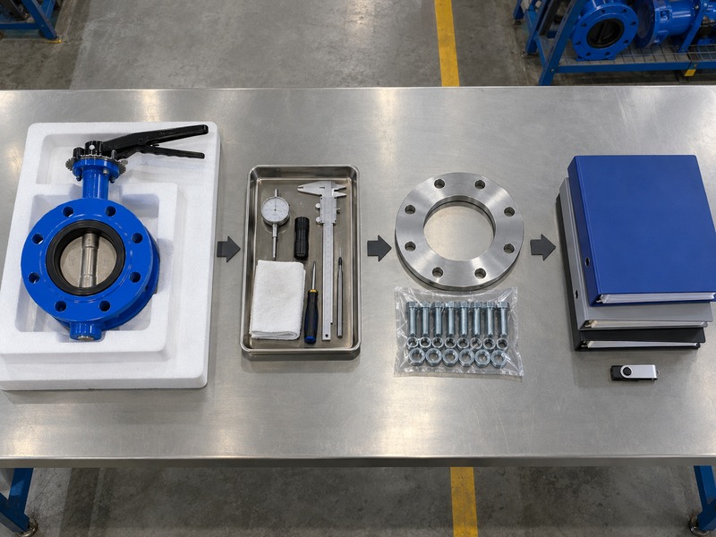
Send RUITO the approved installation drawing, pipe arrangement, fluid, service conditions, operator details, and required inspection package. We can review the proposed DN80 centerline double-flanged assembly and supply the product documents your installation team needs. Contact us before the work package is frozen so the valve instructions and site acceptance requirements can be agreed together.
FAQ
Q1: Can I install the valve as soon as it arrives?
Only after receiving inspection accepts it. Match the identity and documents, check transport condition, and resolve damage or missing parts before installation.
Q2: Can I use a standard bolt torque for every DN80 valve?
No. Use the approved value and procedure for the actual joint. Fasteners, lubrication, flange construction, and sealing arrangement affect the required tightening conditions.
Q3: How do I know whether stiff movement is normal?
Compare it with the manufacturer’s operating guidance. Seat contact can create expected resistance, but new binding after installation requires investigation before applying more force.
Q4: Can I use dry cycling as the final leakage test?
No. Dry cycling checks movement and indication. Closure leakage and installed-system acceptance need their own approved procedures, conditions, and acceptance criteria.
Q5: What’s the best record to keep after commissioning?
Keep the accepted installation file linked to the valve identifier. Include final drawings, assembly checks, commissioning results, instructions, and approved deviations.