
To define triple offset butterfly valve geometry, identify two shaft-axis displacements and the inclined conical sealing axis in the manufacturer’s selected section. These relationships differ from component counts. Leakage, torque, operating limits and approval need their own product evidence.
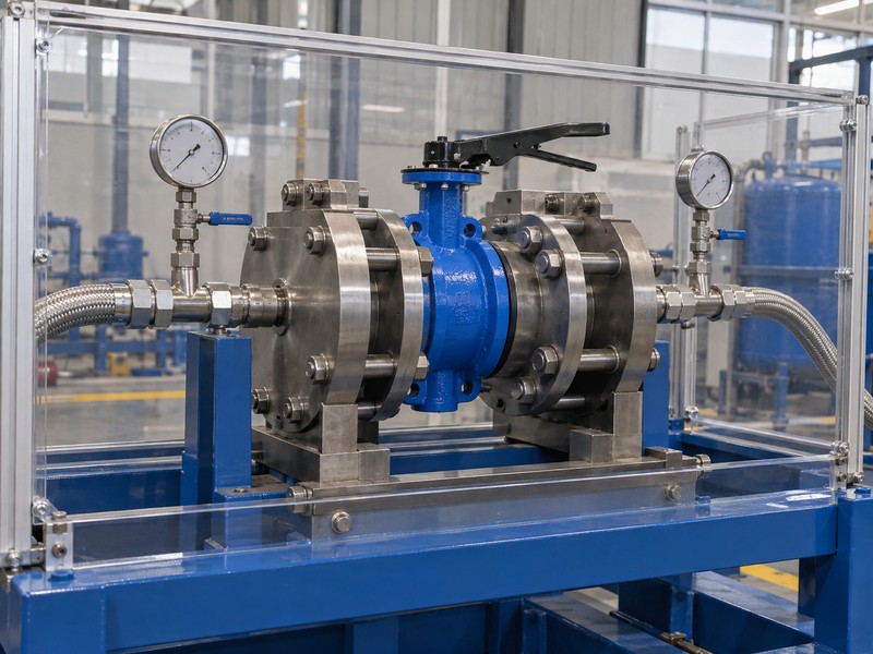
A metal-seat photograph can accompany a triple-offset label without showing any axis reference. A visible sealing ring cannot confirm what is displaced or inclined. Obtain the selected section before accepting an external appearance, parts count or movement illustration as geometry evidence.
1. How should you define triple offset butterfly valve geometrically?
To define triple offset butterfly valve geometrically, state the two designed shaft-axis displacements and the additional inclination of the conical sealing axis. Read those relationships through the actual selected section. The word triple describes this geometric definition and does not establish three stems, three body connections or a particular parts count.
Which three relationships should the reader locate?
Identify the actual reference geometry. Locate the shaft centerline relative to the seat sealing-surface reference and the valve-bore centerline, then identify the conical sealing axis relative to the bore axis. Use the manufacturer’s own view and terminology for the selected model. A generic metallic seat or a catalogue label cannot supply missing reference lines or verify those relationships.
- Locate the shaft against the sealing-surface reference.
- Locate the shaft against the bore-center reference.
- Identify the conical sealing-axis inclination relative to the bore axis.
Key takeaway: Define the three geometric relationships before assigning meaning to the offset count.
| Check | What you should confirm |
|---|---|
| Sealing reference | Selected section defines a shaft-axis displacement |
| Bore reference | Selected section defines the other shaft-axis displacement |
| Conical axis | Selected section defines its inclination relative to the bore axis |
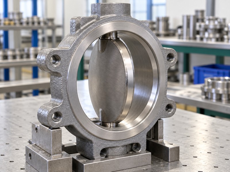
2. What references help you define triple offset butterfly valve?
Reference axes and the sealing-surface definition help you define triple offset butterfly valve without confusing drawn features with physical component counts. Distinguish the bore axis, shaft rotation axis and conical sealing axis in the selected views. Each reference describes a geometric relationship within the actual construction.
How should the views be connected before reading offsets?
Match the model and section references. The Bray Tri Lok-Cx technical manual illustrates its geometry through section and sealing details. Read view orientation, callouts and axis labels before comparing lines. The cone axis references the sealing shape; the shaft axis defines rotation, and nearby labels cannot be exchanged.
- Identify the applicable model and section view.
- Read each axis or sealing reference by its actual label.
- Keep viewing direction and companion references with the interpretation.
Key takeaway: Read the references as distinct geometric definitions before interpreting any displacement or inclination.
| Check | What you should confirm |
|---|---|
| Bore | Passage axis has an identified view reference |
| Shaft | Designed rotation axis is separately located |
| Seal geometry | Conical axis and sealing-surface reference have explicit definitions |
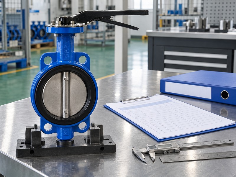
3. What seat offset helps define triple offset butterfly valve?
The shaft displacement from the seat sealing-surface reference helps define triple offset butterfly valve through the selected longitudinal relationship. Identify exactly which surface or reference the manufacturer’s section uses. A visible disc thickness or external shaft position cannot define that offset without the actual geometry and view references.
What should the sealing-reference displacement establish?
Follow the stated sealing reference. Locate the shaft centerline and sealing reference in the section, retaining the manufacturer’s dimension or annotation. Describe that model’s relationship without declaring a universal distance or upstream/downstream arrangement. An unscaled illustration explains the concept but supplies no manufacturing dimension or accepted measurement.
- Locate shaft centerline and the actual sealing-surface reference.
- Read their relationship in the applicable selected section.
- Keep any dimension within its defined drawing and tolerance basis.
Key takeaway: Interpret the sealing-reference offset through the actual section rather than an external outline or assumed distance.
| Check | What you should confirm |
|---|---|
| Reference | Actual sealing-surface definition is identified |
| Location | Section locates the shaft relative to that reference |
| Dimension | Any measured or manufacturing value has a controlled basis |
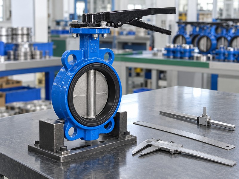
4. What bore offset helps define triple offset butterfly valve?
The shaft displacement from the bore-center reference helps define triple offset butterfly valve by locating its rotation axis in the other defined relationship. Read it independently of the sealing-reference displacement. Two offsets can locate one designed rotation axis without determining how many physical shaft pieces the actual valve uses.
How should the bore-center displacement be described?
Locate the bore and shaft references. Identify their centerlines in the selected drawing and match companion views before assigning direction or distance. Visible hubs, stems and retaining components belong to the parts definition. Counting them cannot replace the geometric reading.
- Read the bore-center and shaft references together.
- Keep this displacement distinct from the sealing-reference offset.
- Separate geometric axis location from actual shaft-piece construction.
Key takeaway: Define the bore-related shaft location without turning offset count into a physical parts count.
| Check | What you should confirm |
|---|---|
| Bore center | Reference follows the actual passage definition |
| Rotation axis | Selected view locates its designed displacement |
| Components | Physical shaft and retention details retain their own parts record |
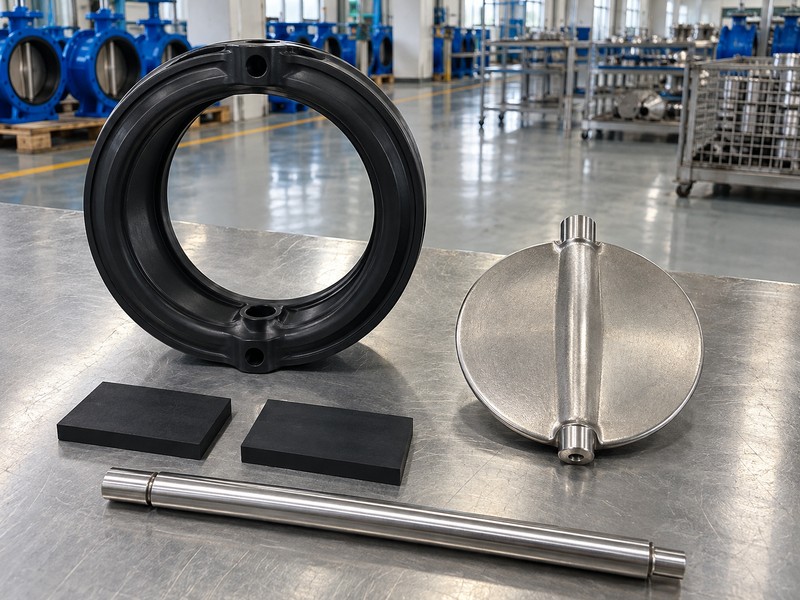
5. What inclined axis helps define triple offset butterfly valve?
The conical sealing axis inclined relative to the bore axis completes the geometric relationships used to define triple offset butterfly valve. It describes the selected sealing shape rather than another physical stem. Locate the axis through the actual conical seat/seal definition instead of judging the slope of an exposed disc face.
Which angular relationship belongs in the definition?
Read the conical-axis definition. Identify the seal geometry and its inclination relative to the bore reference in the manufacturer’s section. Keep angular values and sealing-profile dimensions within that model’s controlled records. A generic ring, perspective distortion or operator travel angle cannot establish this relationship or a universal category value.
- Identify the actual conical sealing axis in the section.
- Read its inclination against the stated bore reference.
- Keep angular values and profiles within the selected design definition.
Key takeaway: Define the angular sealing relationship through its actual axes rather than visible slope or actuator rotation.
| Check | What you should confirm |
|---|---|
| Sealing shape | Selected construction identifies its actual conical geometry |
| Axis relation | Inclination has an explicit bore-axis reference |
| Scope | Any value belongs to the identified model and drawing |
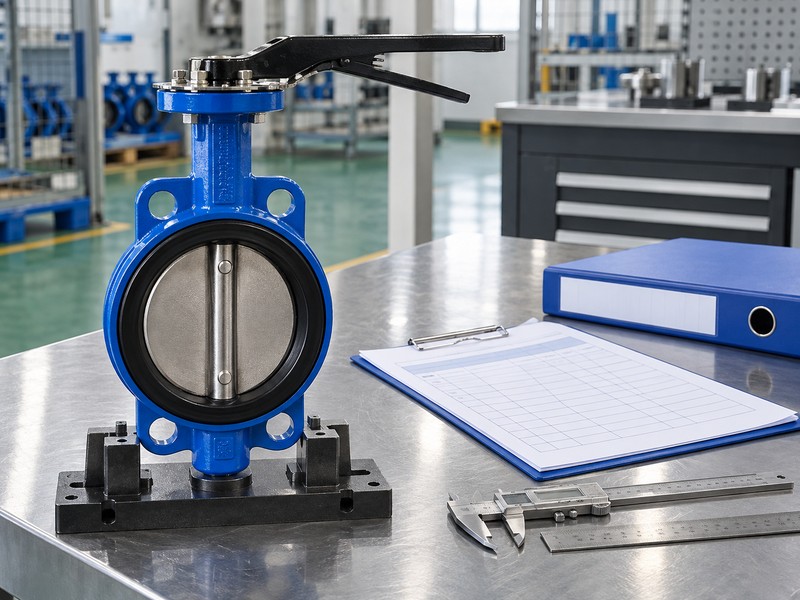
6. What contact terms help you define triple offset butterfly valve?
Contact terms help you define triple offset butterfly valve when they describe the selected sealing pair alongside the geometric references. Read approaching and seated views through the actual model’s definitions. Geometry can explain the intended contact relationship, while torque, wear and leakage acceptance remain separate questions.
What do the selected approach and seated views establish?
Trace the named sealing pair. The Bray Tri Lok-Cx manual shows its seal ring clearing the seat before seating and developing contact by torque loading at closure. Keep that explanation within the identified design. Seat/seal non-rubbing wording cannot establish friction-free bearings, packing or drive components, and the picture supplies no universal release angle, torque reduction or life guarantee.
- Read approaching and seated relationships through selected views.
- Identify the actual seal and seat rather than a generic contact ring.
- Keep complete-valve performance claims within their own evidence.
Key takeaway: Use the selected contact views to explain geometry without converting them into whole-valve performance guarantees.
| Check | What you should confirm |
|---|---|
| Approach | Selected view defines the intended pre-seating relationship |
| Seated | Actual design defines its contact and loading condition |
| Performance | Torque, leakage and durability have separate acceptance bases |
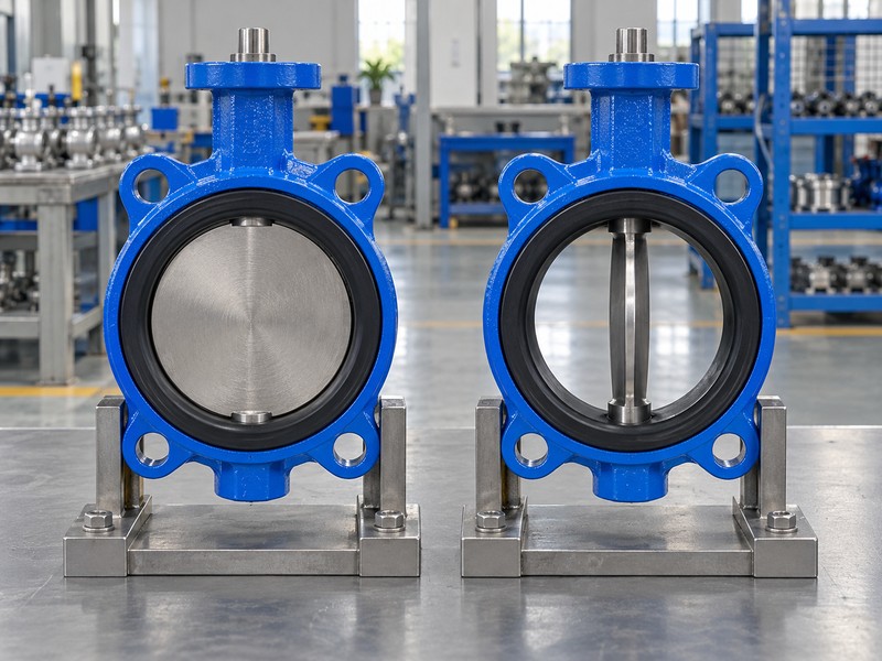
7. Can body labels define triple offset butterfly valve?
Body labels cannot define triple offset butterfly valve by themselves because pipe connection and internal geometry describe separate features. Wafer, lug and double-flanged identify interface arrangements within their actual models. A metallic seat or a particular number of body ends cannot establish the three geometric relationships.
Which construction choices remain outside the offset count?
Identify each classification separately. Record body connection, seat and seal construction, shaft arrangement and geometry in their own fields. Keep flange fit and end-of-line duty within the selected model’s instructions. Exterior images illustrate body style; sections establish internal offsets and conical-axis inclination.
- Keep connection style separate from internal geometry.
- Identify actual seat, seal and shaft construction independently.
- Use selected evidence for interfaces and end-condition duties.
Key takeaway: Keep body, material and geometry descriptions separate when interpreting the proposed valve.
| Check | What you should confirm |
|---|---|
| Connection | Body-interface label identifies the selected pipe arrangement |
| Construction | Seat and shaft details have their own model definitions |
| Geometry | Section establishes the three actual geometric relationships |
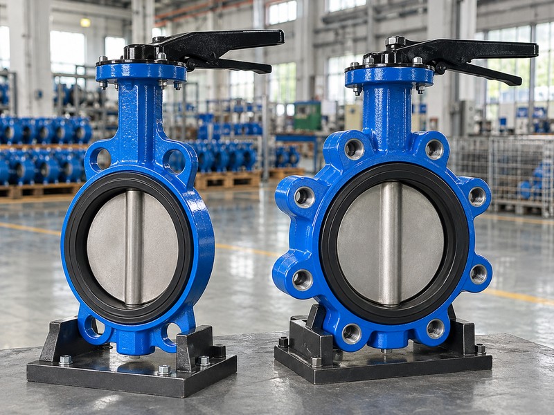
8. Can an operator chart define triple offset butterfly valve?
An operator chart cannot define triple offset butterfly valve unless the selected section separately establishes the actual valve geometry. A manual gearbox describes an input-to-output relationship within the drive. Handwheel turns and shaft rotation do not define displacement from the sealing reference, bore offset or conical-axis inclination.
What does the fixed-ratio chart actually represent?
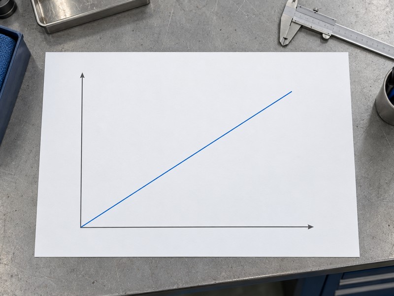
Read the chart’s stated variables. The conceptual figure uses handwheel input turns horizontally and valve-shaft angle vertically for an ideal fixed ratio. Actual turns, permitted endpoints and operator configuration follow the selected drive documents. This motion relationship supplies no offset dimensions, gas or liquid flow, leakage, torque or measured performance result.
- Read operator input and shaft output as drive variables.
- Use selected sections for valve-geometry definitions.
- Keep actual travel and performance within their own records.
Key takeaway: Use the operator chart for its defined drive relationship and the selected section for triple-offset geometry.
| Check | What you should confirm |
|---|---|
| Input | Conceptual horizontal variable represents handwheel turns |
| Output | Conceptual vertical variable represents shaft angle |
| Limit | Ideal ratio illustrates motion without proving geometry or performance |
9. Can performance claims define triple offset butterfly valve?
Performance claims cannot define triple offset butterfly valve accurately without the actual geometric definition. Leakage criteria, operating torque, pressure-temperature limits and approvals address different product questions. A general tight-shutoff or low-torque description cannot identify the shaft offsets or conical sealing axis of the offered construction.
What evidence must remain separate from the definition?
Match each claim with its actual scope. Retain selected model, materials, rated data, directional limits and required test conditions with the relevant acceptance result. Keep any fire, gas, emissions or protective-function claim within its identified product and project coverage. A generic definition or another manufacturer’s named option cannot establish those properties for an unverified construction.
- Define geometry through the actual selected section.
- Retain actual duty and acceptance records for performance claims.
- Confirm approval scope separately for the proposed product and application.
Key takeaway: Use geometry to define the category and scoped product records to establish accepted performance.
| Check | What you should confirm |
|---|---|
| Geometry | Selected section defines axis and sealing relationships |
| Duty | Model-specific data supports required operating conditions |
| Acceptance | Relevant results or approval records cover the actual claim |
10. What records help you define triple offset butterfly valve?
A selected section and clear reference record help you define triple offset butterfly valve for an actual technical request. Identify all three relationships and keep the model and construction scope attached. An unresolved axis, missing reference or generic metal-seat image should remain a documented clarification question.
What should the geometry-review record retain?
Retain the selected geometric basis. Link the model and section with the two shaft displacements and inclined conical sealing axis. Record construction, performance evidence and unresolved questions separately. RUITO can review an identified request and documents, with proposed construction and records confirmed before any supply commitment; this definition establishes no triple-offset offering.
- Identify the actual section and its three geometric references.
- Retain construction and performance records within their separate scope.
- Assign unresolved geometry or proposed-product questions before acceptance.
Key takeaway: Close the definition through the actual section while leaving unverified construction and service claims open.
| Check | What you should confirm |
|---|---|
| Definition | Actual section identifies the three geometric relationships |
| Configuration | Proposed model and construction scope are explicit |
| Evidence | Required duty and acceptance records remain separately traceable |
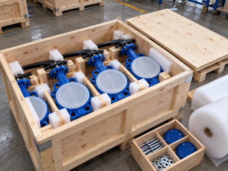
Send RUITO your identified valve request, selected section, required construction and available service documents. We can review the proposed scope and clarify the configuration and records needed for evaluation. Contact us to discuss the actual geometric definition and proposed assembly.
FAQ
Q1: Can triple offset mean three stems or body connections?
No. It describes three geometric relationships: two shaft-axis displacements and the selected conical sealing-axis inclination.
Q2: What’s the best evidence for the inclined sealing axis?
Use the selected section. Identify the actual conical sealing axis and its defined relationship with the bore reference.
Q3: How do I know whether a metal-seat photo shows triple offset?
Request the geometry record. A metallic sealing surface cannot establish the actual shaft displacements or conical-axis inclination.
Q4: Can the handwheel chart establish any of the offsets?
No. It illustrates ideal input turns versus shaft angle, with no offset dimensions or measured geometry evidence.
Q5: How do I know if the definition proves leakage or approval?
Check actual product evidence. Geometry wording cannot replace the selected test criteria, recorded results or approval coverage for the proposed construction.