
Fix geometry mistakes by reading a double eccentric butterfly valve through its selected section drawing, rotation axis and seat references. Trace how the disc moves about that axis before interpreting cam-like lift-off or a motion animation. Keep geometry evidence separate from the selected assembly’s leakage, torque and operating-limit records.
A motion animation can show a clear gap between disc and seat while the quotation identifies no section drawing or seat variant. The movement looks plausible, yet your reviewer cannot confirm the axes, contact relationship or configuration behind it. Start with the defined geometry so purchasing and engineering can ask for evidence that describes the actual proposed assembly.
1. What defines a double eccentric butterfly valve?
A double eccentric butterfly valve uses two designed displacements to locate its rotation axis relative to the seat-plane and bore-center references. Double offset is another description used for this geometry. Confirm how the selected manufacturer defines those references before treating the name as a complete construction specification.
Which definitions should accompany the product name?
Request the geometry reference. Obtain the model, body connection, seat arrangement and controlled section drawing. Its directions and dimensions locate one designed rotation axis. Connection, materials, permitted pressure direction and approvals still need supporting configuration records beyond the double-eccentric label.
- Identify the actual model and selected body connection.
- Request a section drawing with defined geometry references.
- Keep seat, duty and approval records linked to that configuration.
Key takeaway: Use the name to identify a geometry concept, then verify the selected construction through controlled documents.
| Check | What you should confirm |
|---|---|
| Name | Double eccentric or double offset has a defined model context |
| Axis | Two displacements locate the designed rotation reference |
| Construction | Body and seat details have their own definitions |
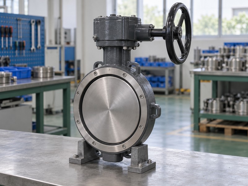
2. Where is a double eccentric butterfly valve axis?
The axis of a double eccentric butterfly valve is located by displacement from the seat sealing plane and from the bore or seat centerline in the other direction. Read those locations through the selected drawing’s views and datums. Numbering and terminology should follow that manufacturer rather than a remembered generic sketch.
How should the reviewer follow the two displacements?
Trace the axis across views. The Keystone K-LOK technical sheet depicts its shaft displacements against seat references. Match the views with the same assembly, axis, plane and centerline before reading dimensions. Visual estimation cannot supply an offset measurement where defined datums are missing.
- Locate the rotation axis in the applicable section views.
- Identify the seat plane and centerline references.
- Read actual dimensions from controlled datums and annotations.
Key takeaway: Follow one rotation axis through the defined views instead of inferring offsets from an external outline.
| Check | What you should confirm |
|---|---|
| Seat plane | Defined view shows the relevant axial displacement |
| Centerline | Companion reference locates the other designed displacement |
| Datums | Dimensions use the selected drawing’s physical references |
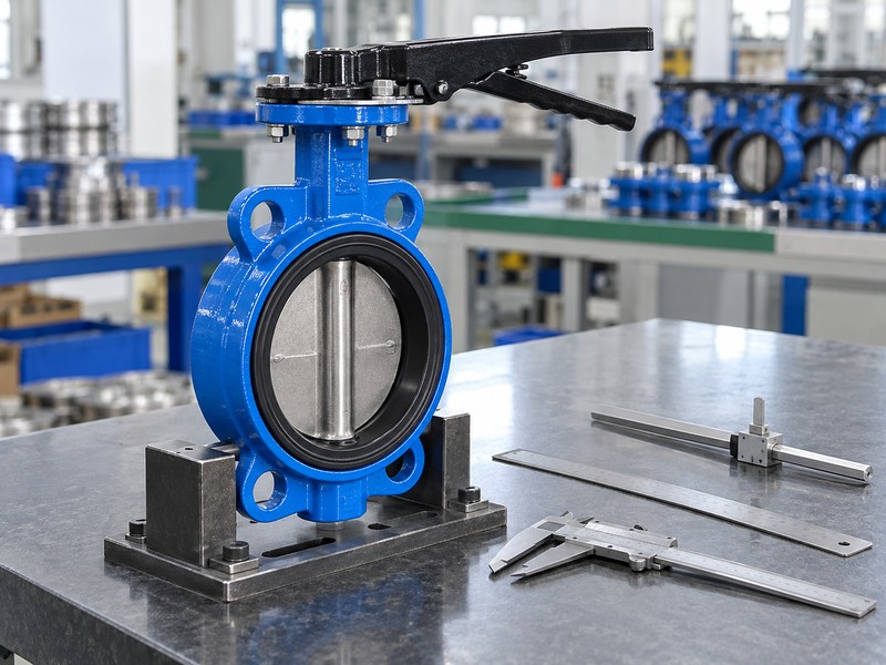
3. How does a double eccentric butterfly valve disc move?
The disc of a double eccentric butterfly valve rotates with its shaft about the designed offset axis. That geometry can produce cam-like separation between the sealing surfaces as opening proceeds. The familiar quarter-turn description concerns nominal rotary travel; actual permitted endpoints and settings follow the selected valve and operator instructions.
What does cam-like lift-off describe?
Follow the rotating assembly. Track the disc edge against the stationary seat through defined positions. Lift-off describes changing separation during rotation of the shaft-driven assembly. A schematic gap cannot establish a universal release angle, contact-free full stroke or the movement relationship of another seat design.
- Trace disc rotation about the selected shaft axis.
- Read separation as a changing disc-to-seat relationship.
- Use actual instructions for permitted travel and endpoint settings.
Key takeaway: Interpret lift-off through the disc’s rotation and the actual seat geometry.
| Check | What you should confirm |
|---|---|
| Rotation | Disc movement follows the designed axis |
| Separation | Cam-like movement changes local disc-to-seat clearance |
| Travel | Accepted endpoints belong to the selected assembly |
4. What contacts a double eccentric butterfly valve seat?
The selected disc sealing region contacts the seat of a double eccentric butterfly valve as the valve reaches its accepted closed condition. Geometry can reduce rubbing during parts of opening and closing, but contact remains part of the sealing design. Actual material, deformation and loading determine the relevant sealing behavior.
Which contact claims need separate evidence?
Identify the sealing construction. Record the seat, disc sealing surface and acceptance requirement with the model. Polymer, elastomer, metal and combined seats can differ in contact and leakage behavior within one geometry family. A visible gap cannot establish zero leakage, guaranteed cycle life or exemption from required inspection and maintenance.
- Identify the actual seat and disc sealing surfaces.
- Retain the selected leakage method and acceptance criteria.
- Request evidence for quantified wear or service-life claims.
Key takeaway: Use geometry to explain possible contact behavior and actual test records to establish accepted performance.
| Check | What you should confirm |
|---|---|
| Contact | Selected construction defines the sealing relationship |
| Materials | Seat and disc surfaces match the identified configuration |
| Performance | Leakage and durability claims have their own supporting evidence |
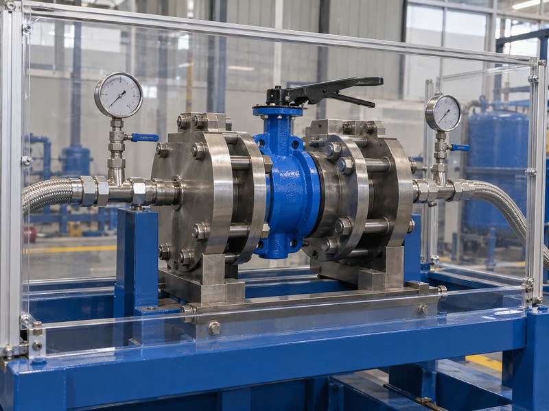
5. What drawing explains a double eccentric butterfly valve?
A controlled section drawing explains a double eccentric butterfly valve when it identifies the actual shaft, disc, seat and geometric references. A general arrangement provides installation dimensions but may leave those internal relationships concealed. Use the section and assembly records together before deciding what the offered construction contains.
What should a drawing package make traceable?
Match the document identities. Connect the section drawing with the model, component list, seat and accepted general arrangement. Read notes and revisions for options absent from the quoted assembly. Request the selected dimensional definition where a schematic view leaves it unresolved; do not scale the illustration.
- Identify shaft, disc and seat through the selected section.
- Match the section with the assembly and component records.
- Separate schematic relationships from controlled dimensional definitions.
Key takeaway: Approve geometry from an identified drawing package whose views and component definitions agree.
| Check | What you should confirm |
|---|---|
| Section | Internal geometry and component relationships are defined |
| Assembly | General arrangement and parts describe the same variant |
| Control | Document status and revisions support the review decision |
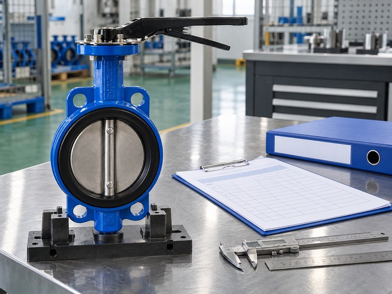
6. What can a double eccentric butterfly valve photo prove?
A photograph of a double eccentric butterfly valve can document visible external condition and identification within the limits of its view. It cannot reliably define concealed shaft offsets, seat contact or controlled dimensions. Perspective, partial visibility and an unscaled image leave those internal relationships unresolved.
How should product images support the review?
Record what is visible. Link actual photographs of markings, external arrangement and condition with the identified assembly. Generic illustrations cannot establish manufacture, measurement or acceptance. An apparently off-center disc in a perspective view needs the selected section drawing before your reviewer can attribute its appearance to a particular offset geometry.
- Identify visible markings and external features accurately.
- Link actual photographs with the relevant assembly identity.
- Use controlled drawings for concealed geometry and dimensions.
Key takeaway: Use photographs to support identifiable external observations while retaining drawings for geometry decisions.
| Check | What you should confirm |
|---|---|
| Visible | Photograph records only the accessible view |
| Identity | Actual product image has a traceable assembly reference |
| Hidden | Offsets and seat relationships require separate design evidence |
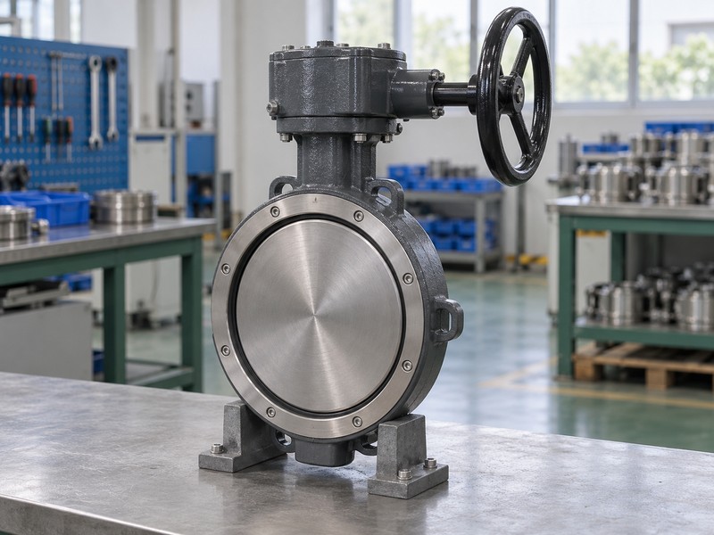
7. Can a double eccentric butterfly valve animation mislead?
A double eccentric butterfly valve animation can mislead when its geometry, contact assumptions or motion scale are unspecified. A visual model can illustrate the relationships it contains, but omitted seat deformation or constraints can change the interpretation. Read it against the selected design rather than accepting a smooth sequence as physical verification.
Which assumptions belong beside a motion model?
Identify the model basis. Request the represented assembly, revision, axis definitions and whether clearance or contact behavior is schematic. A kinematic sequence alone cannot establish pressure loading, operating torque, leakage or wear performance. Any simulation-based analysis needs its own documented assumptions, method and validation for the claimed result, with physical acceptance evidence retained where the project requires it.
- Identify the actual or conceptual geometry being animated.
- Record assumptions about clearances, contact and movement.
- Separate illustrated motion from validated performance analysis.
Key takeaway: Treat animation as defined model evidence whose usefulness depends on its stated assumptions.
| Check | What you should confirm |
|---|---|
| Geometry | Model identifies its represented assembly and references |
| Assumptions | Included and simplified contact relationships are stated |
| Claim | Any analytical result has a documented validation basis |
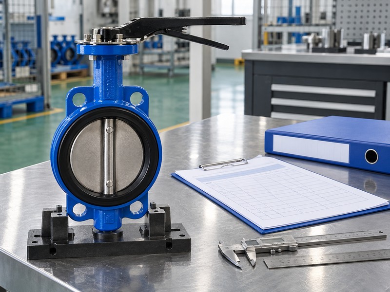
8. How is a double eccentric butterfly valve distinct?
A double eccentric butterfly valve differs from a concentric arrangement through its defined shaft-axis displacements. Triple-offset construction adds an angular sealing-geometry relationship identified by that design. Those descriptions concern geometry, while wafer, lug and double-flanged describe body connections and need their own configuration definitions.
What should a brief geometry comparison leave unresolved?
Compare the actual references. Read concentric centering, double-offset axis location and additional angular sealing geometry through selected drawings. Those labels cannot rank leakage, permitted media, torque or maintenance requirements across all products. Request construction-specific evidence before accepting a performance or interchangeability claim.
- Compare geometric references through actual section drawings.
- Keep body connection separate from offset classification.
- Review seat and duty claims within their selected configurations.
Key takeaway: Distinguish geometric arrangements without turning their names into universal performance rankings.
| Check | What you should confirm |
|---|---|
| Concentric | Centered geometry follows the selected construction’s references |
| Double offset | Two displacements define the designed shaft-axis location |
| Triple offset | Additional angular sealing geometry has its own definition |
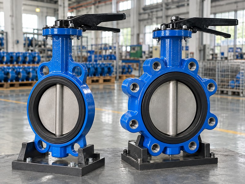
9. What limits a double eccentric butterfly valve?
A double eccentric butterfly valve remains limited by its actual seat, structural components, operating conditions and selected drive. Cam-like movement cannot establish permitted differential pressure or actuator size. Review seating, unseating, running and relevant fluid torque beside the stem and operator limits for the same configuration.
How should geometry connect with the operating envelope?
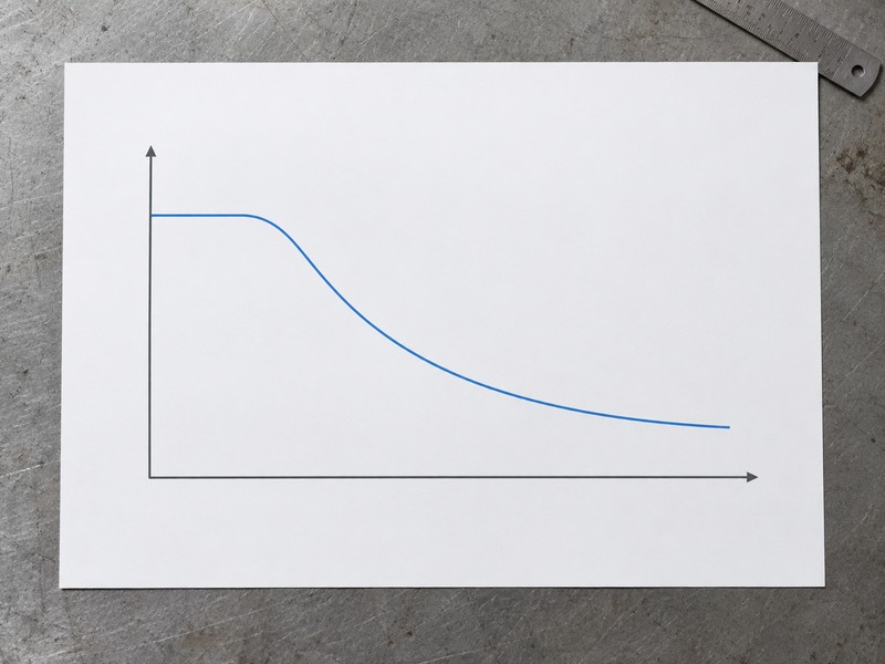
Check the selected duty. Retain the model’s pressure-temperature relationship, forward and reverse differential limits and actual torque basis with its seat and materials. The Bray McCannalok manual distinguishes construction-specific instructions within its identified family. The conceptual chart supplies no numerical model rating, while actual operator output and allowable drive loads need their own documented comparison.
- Keep pressure-temperature limits tied to the actual configuration.
- Compare valve demand with permitted drive and operator limits.
- Review direction-dependent duty through the selected instructions.
Key takeaway: Connect the geometry explanation with actual duty data before accepting an operating or actuator claim.
| Check | What you should confirm |
|---|---|
| Duty | Actual conditions remain within selected component limits |
| Torque | Demand and permitted drive loads have identified bases |
| Operator | Actual output suits the required duty without exceeding limits |
10. What verifies a double eccentric butterfly valve?
Verify a double eccentric butterfly valve through the identified construction, controlled geometry and required inspection or test evidence. Keep those records linked to the same model and revision. A drawing can define the intended design, while the specified dimensional, material and functional records establish the required acceptance evidence for the actual assembly.
What should the buyer retain before approving the request?
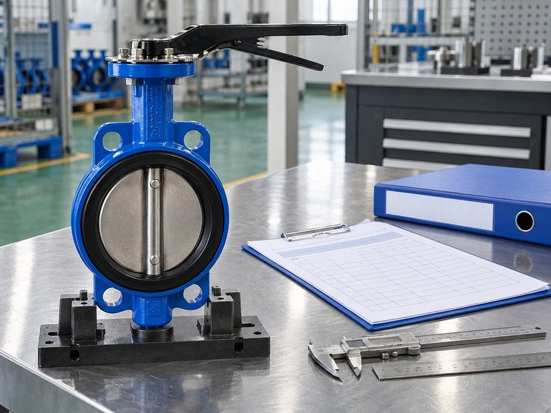
Link design and acceptance records. Retain the selected section, general arrangement, component definitions, applicable manuals and required verification results. Confirm the requested body connection independently; separately documented concentric-wafer and double-flanged double-offset constructions cannot define a combined product. RUITO can review an identified request and its available documents, with the actual proposed configuration and supporting evidence confirmed before any supply commitment.
- Retain the identified geometry and assembly drawing package.
- Link required verification results with actual product identity.
- Confirm requested configuration and any approval scope separately.
Key takeaway: Accept one traceable construction whose geometry, service definition and required verification records agree.
| Check | What you should confirm |
|---|---|
| Design | Selected geometry and component definitions agree |
| Acceptance | Required records identify the actual assembly and criteria |
| Request | Proposed construction has confirmed supporting documentation |
Send RUITO your identified valve request, body connection, seat requirements, operating conditions and existing section or assembly drawings. We can review the request and clarify which actual configuration and supporting documents would be needed for evaluation. Contact us before accepting geometry or motion visuals as a substitute for the selected assembly’s design and acceptance records.
FAQ
Q1: Can I identify both offsets from an exterior product photo?
No. Use the selected section drawing with defined axis, seat-plane and centerline references; external appearance cannot establish concealed dimensions.
Q2: What’s the best way to read cam-like lift-off?
Track disc rotation. Compare successive positions with the actual seat geometry rather than treating an opening gap as a separate translating mechanism.
Q3: How do I know if an animation represents the offered valve?
Check its model basis. Match assembly identity, revision, axes and contact assumptions with the supplied design documents.
Q4: Can I assume double eccentric means metal seated?
No. Seat construction remains model-specific and needs its own materials, service limits and acceptance requirements.
Q5: How do I know whether the geometry proves a torque reduction?
Request comparative evidence. Actual torque depends on the selected seat, service conditions, movement duty and documented comparison basis.