
Fix design mistakes by reviewing the connections between geometry, loads, sealing and the external interfaces before releasing drawings. A double offset butterfly valve design needs a defined operating basis and traceable evidence for its complete mechanical arrangement. Individual component drawings must agree with the assembly, inspection scope and permitted repair configuration.
A revised seat can change its retention interface while the shaft drawing and spare-parts list still describe an older assembly. Each document may appear complete in isolation, yet the combined package leaves load transfer or repair compatibility unresolved. Trace the connected design decisions and close those conflicts before manufacturing or replacement parts are released.
1. What defines a double offset butterfly valve design review?
A double offset butterfly valve design review starts with one controlled assembly and its required service cases. Identify body style, seat arrangement, shaft axis and sealing references without transferring details from another family. Double offset defines internal geometry, while wafer, lug and double-flanged describe separate connection constructions.
Which design references need a common basis?
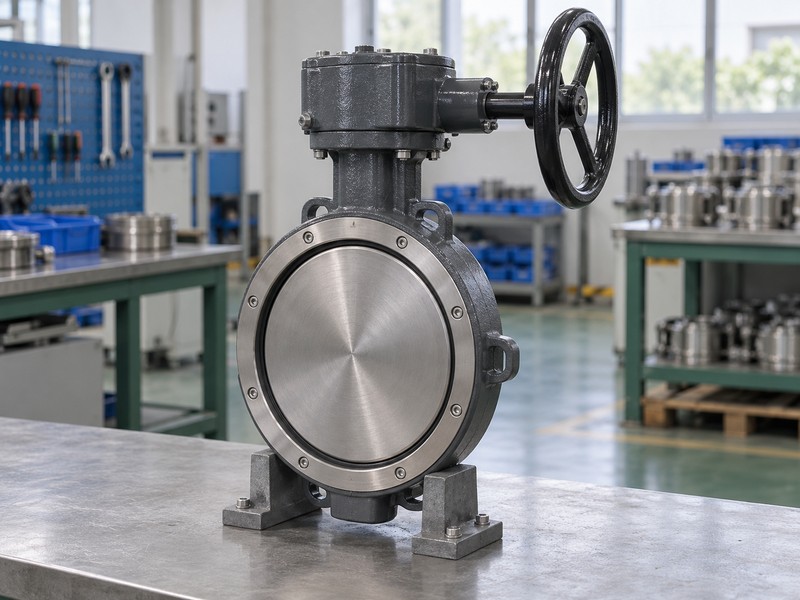
Fix the assembly definition. The Keystone K-LOK technical sheet illustrates offset relationships for its identified construction; use the selected drawing’s actual references and definitions. For a proposed RUITO configuration, confirm the body and geometry combination rather than combining separate wafer and double-flanged product descriptions. An exterior illustration cannot establish internal offsets, tolerances or an accepted design.
- Identify one assembly and its controlled drawing revision.
- Separate body connection from internal offset geometry.
- Use selected section views for actual design references.
Key takeaway: Review the identified construction through connected drawings and service requirements rather than a category sketch.
| Check | What you should confirm |
|---|---|
| Assembly | Body, seat and drive describe one selected construction |
| References | Section views identify the actual axis and sealing relationships |
| Basis | Required service cases accompany the reviewed revision |
2. What loads govern a double offset butterfly valve design?
In a double offset butterfly valve design, pressure, operating torque and external reactions act through different connected parts. Review how the selected disc, seat, shaft, bearings, body and mounting arrangement carry those actions. A body pressure class alone cannot describe every internal load or drive requirement.
What must the load-path review establish?
Trace each required load case. Identify pressure direction and differential, opening and closing conditions, relevant flow forces and the stated operator or external mounting loads. Document which components and interfaces resist them under the selected design basis. Keep load assumptions and supporting calculations or validation evidence with the drawings instead of substituting an unexplained allowance or a generic actuator rating.
- Identify pressure, movement and external loading cases.
- Trace reactions through the actual connected components.
- Retain the assumptions behind calculations or validation evidence.
Key takeaway: Record where required loads enter and how the assembly resists them.
| Check | What you should confirm |
|---|---|
| Pressure | Selected direction and differential define the reviewed case |
| Operation | Drive and relevant fluid loads have an identified basis |
| Reaction | Connected parts and supports carry their assigned actions |
3. What retains a double offset butterfly valve design seat?
Seat retention in a double offset butterfly valve design must preserve the selected sealing arrangement under its permitted pressure directions and service conditions. Identify the retaining parts and their connection with the body. Seat-retainer fasteners and pipe-flange bolting serve different interfaces and cannot be treated as an interchangeable restraint system.
How should retention and end conditions be reviewed?
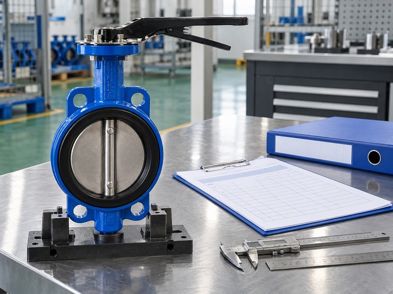
Identify the complete retaining arrangement. The Bray McCannalok technical manual separates seat and body constructions, including body-specific dead-end capability in its identified family. That example does not establish the same capability for another wafer design. Review seat location, retainer attachment, pressure direction and actual end restraint through the selected documents rather than an isolated retainer illustration.
- Identify seat-retaining components and body attachments.
- Separate retainer hardware from external pipe-flange bolting.
- Check actual pressure direction and end-restraint conditions.
Key takeaway: Review retention and end-of-line duty through the documented attachment and loading basis.
| Check | What you should confirm |
|---|---|
| Seat location | Selected parts preserve the intended sealing arrangement |
| Retention | Attachment details have a documented mechanical basis |
| End condition | Actual body and restraint support the requested duty |
4. What drives a double offset butterfly valve design disc?
The drive path in a double offset butterfly valve design connects operator movement with the disc through the selected shaft and attachment arrangement. Review how each joint transfers torque and maintains the accepted relationship between indicated and actual disc position. A matching mounting face does not establish that complete path.
Which joints and limits need design evidence?
Review the connected drive. Identify disc-to-shaft attachment, shaft retention, coupling geometry and mounting details from the selected assembly rather than assuming a universal pin, key or divided-shaft construction. Check required operating torque and permissible connected-part loads at their stated application points. Retain the selected stop and travel definition so a revised drive cannot silently alter seating or overload another component.
- Identify every joint from operator output to disc.
- Compare demanded and permitted loads at matching locations.
- Retain accepted travel and stop definitions with the drive review.
Key takeaway: Verify torque transfer and movement through the complete drive path.
| Check | What you should confirm |
|---|---|
| Joint | Actual shaft and disc attachment are defined |
| Capacity | Connected parts support their required operating loads |
| Travel | Drive movement agrees with accepted disc and seat limits |
5. What supports a double offset butterfly valve design shaft?
Shaft support in a double offset butterfly valve design influences alignment, movement and the relationship between disc and seat. Identify bearings, bushings, spacers and thrust or locating components according to the selected construction. Packing provides external shaft sealing and needs its own defined arrangement rather than an assumed support duty.
How should support and sealing interfaces be connected?
Locate the shaft support. Review the components that establish radial and axial location, their permitted loads and their relationship with the sealing references. Keep packing, gland and retention details identifiable so support changes receive a corresponding shaft-seal review. Reduced disc-to-seat rubbing cannot establish a friction-free bearing system, eliminate deflection questions or replace the selected maintenance requirements.
- Identify radial, axial and locating functions separately.
- Connect support definitions with disc and seat alignment.
- Review shaft sealing when support or retention changes.
Key takeaway: Review shaft support and sealing as connected functions with distinct duties.
| Check | What you should confirm |
|---|---|
| Support | Selected components locate the shaft under required loads |
| Alignment | Support relationships preserve the reviewed sealing arrangement |
| Sealing | Packing and gland retain their defined external-leakage duty |
6. What interfaces fit a double offset butterfly valve design?
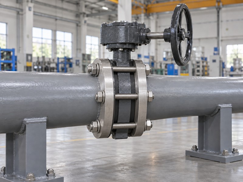
A double offset butterfly valve design review includes the body-to-pipe connection and the operator’s external attachment. Those interfaces must preserve the intended internal arrangement under the stated installation and loading assumptions. Keep flange construction, disc envelope, mounting reactions and maintenance space visible on the selected interface drawings.
What should the external interface drawing establish?
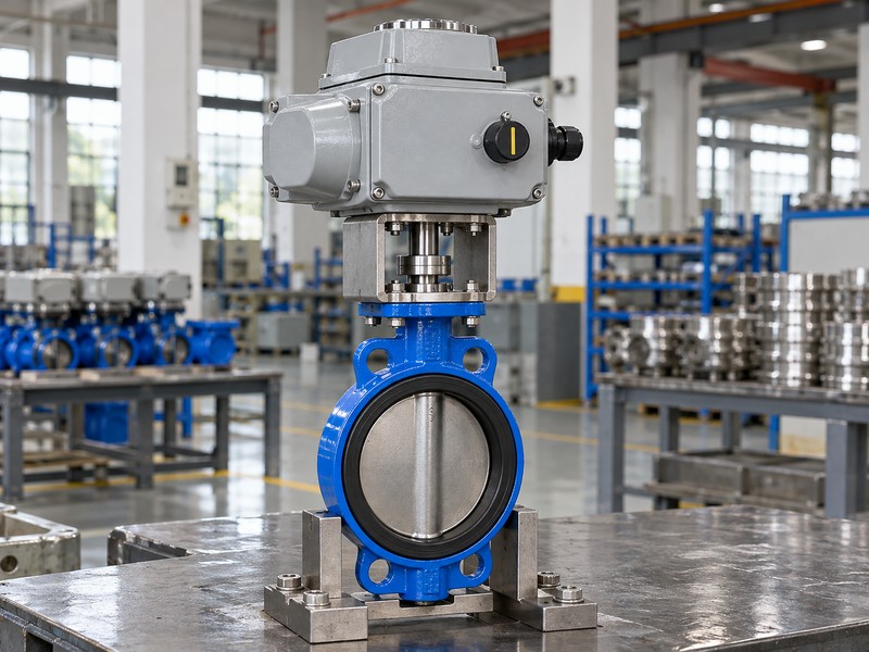
Define the mating boundaries. Identify the actual flange and gasket arrangement, bolting requirements, disc sweep and operator mounting definition without importing another valve’s dimensions or restraint assumptions. Review any adjacent pipe, lining or support condition that affects the selected mechanical envelope. The static layout illustrates external relationships only; its hidden joints cannot establish accepted bolting, clearance or pressure suitability.
- Retain selected body and operator mating definitions.
- Identify required disc movement and external reaction assumptions.
- Include adjacent restrictions and maintenance space in the review.
Key takeaway: Review external interfaces for their effect on restraint, movement and access.
| Check | What you should confirm |
|---|---|
| Body interface | Pipe connection matches the selected design definition |
| Operator interface | Mounting and reactions support the intended drive |
| Envelope | Moving and service-access boundaries are identified |
7. What materials suit a double offset butterfly valve design?
Material choices in a double offset butterfly valve design must support mechanical loads, fluid compatibility and the actual temperature conditions. Review body, disc, shaft, seat, packing and support materials within the same configuration. Substituting one grade can affect connected clearances, sealing behavior or permitted service even when its nominal strength appears suitable.
How should thermal compatibility enter the design review?
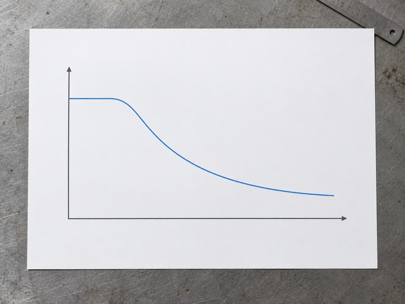
Review materials as a connected set. Assess the relevant thermal behavior and operating clearances through the selected design basis rather than inventing a universal expansion allowance. Retain pressure-temperature and compatibility restrictions for the actual configuration, including stated operating and cleaning conditions. The conceptual chart reads temperature increasing rightward and allowable pressure upward; it supplies no dimensions, thermal movement calculation, material curve or universal derating rule.
- Identify actual grades and sealing-material arrangements.
- Review thermal behavior at connected fits and interfaces.
- Keep service limits and material substitutions within controlled review.
Key takeaway: Review each material substitution for connected mechanical and sealing effects.
| Check | What you should confirm |
|---|---|
| Materials | Selected grades support actual loads and exposure |
| Temperature | Relevant fits and sealing relationships have a reviewed basis |
| Limits | Configuration-specific operating restrictions remain traceable |
8. What service access suits a double offset butterfly valve design?
A double offset butterfly valve design should identify how permitted maintenance and replacement can be performed within its actual assembly arrangement. Review access to packing, retainers, operators and replacement components through selected instructions. Removable-looking hardware does not establish in-line repair capability or permit arbitrary replacement parts.
Which repair assumptions belong in the design package?
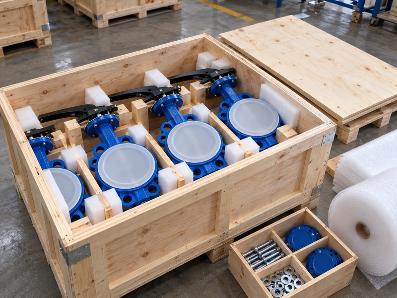
Define the permitted repair configuration. The Bray McCannalok installation and maintenance manual identifies matched disc-and-stem replacement for its stated standard arrangement, illustrating why spare definitions matter. Other designs need their own instructions, component relationships and access requirements. Retain authorized repair scope and replacement identities without turning an assembly drawing into a generic disassembly or modification procedure.
- Review required access against selected maintenance instructions.
- Identify matched or configuration-specific replacement components.
- Retain limits on permitted repair and substitution scope.
Key takeaway: Retain repair access and permitted spare relationships in the design and handover package.
| Check | What you should confirm |
|---|---|
| Access | Selected instructions define the required service boundaries |
| Spares | Replacement identities preserve the accepted component relationships |
| Work scope | Authorized repair follows the actual product procedure |
9. What verifies a double offset butterfly valve design?
Verification of a double offset butterfly valve design needs records that connect critical drawing requirements with manufactured and assembled features. Identify which dimensions, materials, fits and functional relationships require inspection. A complete drawing package cannot by itself establish that the delivered assembly meets those requirements.
Which manufacturing records support the design intent?
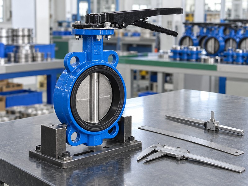
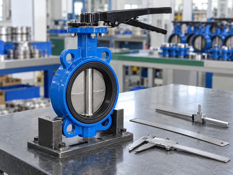
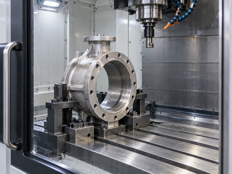
Link requirements with recorded evidence. Retain the controlled manufacturing and inspection definition, actual material identity and required dimensional or assembly results against the supplied valve. Keep functional movement, pressure and leakage evidence within their separately stated acceptance scopes. A generic stationary fixture illustration demonstrates no cutting pass, achieved tolerance or actual RUITO manufacturing record, and its appearance cannot replace inspection results.
- Identify inspection requirements for critical design relationships.
- Link actual material and assembly evidence with supplied identity.
- Keep dimensional, functional and pressure evidence within stated scope.
Key takeaway: Connect controlled requirements with traceable manufacturing and assembly evidence.
| Check | What you should confirm |
|---|---|
| Requirement | Drawing and inspection definitions identify what must be verified |
| Record | Actual results connect with the supplied assembly |
| Acceptance | Methods and criteria address their stated design functions |
10. What changes a double offset butterfly valve design?
A change to a double offset butterfly valve design can affect more than the revised component. Seat construction, shaft attachment, bearing material, retainer hardware or body style can alter connected loads and acceptance requirements. Review the affected assembly relationships before describing a replacement or new revision as equivalent.
How should design changes reach the accepted records?
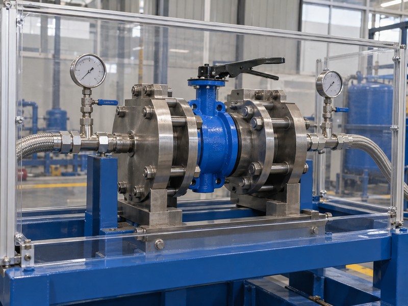
Control the affected configuration. Record the reason, revised drawings and parts definition, load or compatibility impacts and required inspection or qualification updates through the applicable change process. Identify which spare parts and maintenance instructions remain valid, then update the release package. A pressure-test record supports its stated test scope; it cannot establish that every changed geometry, material and drive relationship has received the required review.
- Identify connected load, fit and sealing effects of changes.
- Update drawings, parts and required verification scope coherently.
- Retain accepted decisions and replacement compatibility information.
Key takeaway: Update the accepted assembly definition, supporting evidence and repair information after a design change.
| Check | What you should confirm |
|---|---|
| Impact | Affected mechanical and service relationships are identified |
| Revision | Drawings, parts and instructions describe the changed assembly |
| Release | Required review and verification evidence accompany acceptance |
Send RUITO the identified body style, service cases, assembly drawings and proposed design or replacement change. We can review the supplied application information and identify which configuration, interface or verification records still need confirmation. Contact us before releasing a revised arrangement or assuming that separate product configurations are interchangeable.
FAQ
Q1: Can an exterior photograph prove the offset dimensions?
No. Use the selected manufacturer’s controlled section drawings and design references to establish the actual geometry.
Q2: Are seat-retainer screws the same as pipe-flange bolts?
No. They serve different interfaces. Review the actual seat retention, body connection and end-restraint arrangement separately.
Q3: Does a stronger shaft material make a drive change equivalent?
No. Review attachment, coupling, retention, connected loads, travel and compatibility across the complete drive path.
Q4: Can any removable seat be repaired in line?
No. Permitted repair scope, access and replacement relationships follow the selected product’s instructions and accepted project arrangement.
Q5: What must accompany a changed seat or bearing material?
Retain review of affected loads, fits, sealing, temperature and service limits, with updated drawings, parts and required verification evidence.