
Fix test mistakes around a tamper switch on butterfly valve assemblies by identifying the asset, documenting its actual condition and comparing that evidence with the correct system report. Use the selected product instructions and an authorized work plan for physical investigation. A cleared display alone cannot establish that the installed arrangement works as required.
A recurring valve supervisory report can send maintenance staff back to a handwheel that already appears open. Changing parts before identifying the actual point, expected position and observed contact behavior can leave the cause unresolved. Start with a traceable condition report so the responsible technician can investigate the disagreement and document what restores the required service condition.
1. How do you identify a tamper switch on butterfly valve issue?
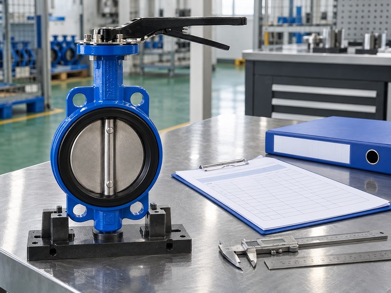
Identify a tamper switch on butterfly valve issue by tying the reported symptom to a specific installed asset. Record the valve tag, location, operator model and available switch identification before interpreting the report. Similar housings can serve different zones, leaving a location-only description ambiguous.
What should the initial condition report contain?
Record the observed symptom. Keep event text, point identity and chronology beside photographs of accessible labels and external condition. Note whether the report followed planned work, appeared intermittently or remained present, without assuming a cause. Matching product documents and accepted records help the technician distinguish new conditions from documentation discrepancies.
- Identify the physical valve and its operator configuration.
- Retain exact event text and associated point information.
- Describe observed conditions without naming an unverified failed part.
Key takeaway: Begin with an identifiable asset and recorded symptom before choosing a corrective action.
| Check | What you should confirm |
|---|---|
| Asset | Valve tag and location identify the actual assembly |
| Symptom | Event text and chronology preserve the observed report |
| Baseline | Selected manuals and accepted records accompany the investigation |
2. What is normal for a tamper switch on butterfly valve setup?
The normal condition for a tamper switch on butterfly valve setup comes from its intended service position and selected configuration. A supervised-open supply valve normally remains fully open. Its contact continuity in that position still follows the exact switch arrangement, so an open valve position cannot establish a universal NO or NC connection.
Which reference should the service team use?
Confirm the intended position. Match the valve model and accepted project function with the manufacturer’s position reference. The TYCO BFV-300/BFV-300C technical sheet identifies distinct open-supervised and closed-supervised models. Retain that model identity in the service record; generic photographs cannot establish the required normal state.
- Identify the valve’s intended supervised service position.
- Match that position with the actual supplied model.
- Read expected contact states from the selected product documentation.
Key takeaway: Define normal mechanical position and expected electrical state separately before judging the symptom.
| Check | What you should confirm |
|---|---|
| Service | Intended normal position follows accepted project requirements |
| Model | Actual variant supports the specified supervised condition |
| Contacts | Expected continuity follows its documented position reference |
3. Can a tamper switch on butterfly valve match the pointer?
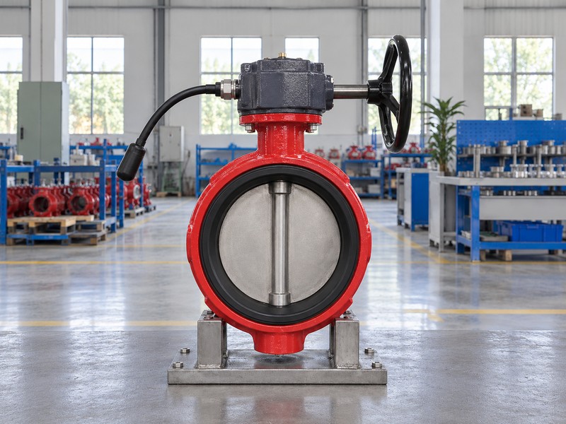
A tamper switch on butterfly valve can agree with its pointer only when their relationship to actual valve position has been verified. A visible pointer reports the operator’s indication, while the selected switching mechanism has its own documented relationship with movement. An apparent agreement at rest cannot establish the full operating relationship or required departure response.
What evidence distinguishes indication from valve function?
Separate the observations. Record external indication, available mechanical evidence and authorized switch-test results as distinct findings. Qualified personnel must follow the selected instructions when the actual position or mechanism relationship remains uncertain; the pointer alone cannot authorize stop or cam adjustment. Position supervision also cannot establish available flow, an unobstructed waterway or acceptable seat leakage, which require their own evidence.
- Record pointer indication without treating it as complete verification.
- Use selected procedures for the mechanical and switching relationship.
- Keep hydraulic findings separate from supervisory signal results.
Key takeaway: Compare the pointer, monitored mechanism and electrical result without treating them as interchangeable evidence.
| Check | What you should confirm |
|---|---|
| Indication | External pointer condition is recorded as observed |
| Relationship | Mechanical and switching evidence follows selected procedures |
| Hydraulics | Flow and leakage require separate verification |
4. Does a tamper switch on butterfly valve report trouble?
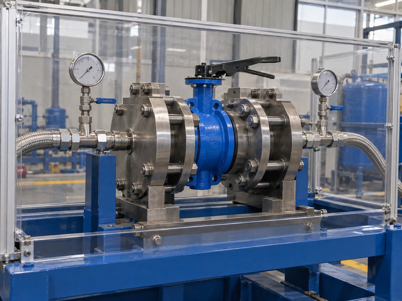
A tamper switch on butterfly valve contributes a contact state that the selected input and system configuration interpret. A supervisory event and a circuit-trouble report can describe different conditions. Their meanings depend on the actual input topology and programming, so the event category cannot identify a failed switch without supporting observations.
How should the team classify an off-normal report?
Keep the event wording. Compare the recorded event with the selected input’s documented normal, activation and specified fault responses. A circuit break, short or contact change may produce different reports across input designs. The responsible technician should identify where observed behavior departs from the accepted state table before components or settings change.
- Preserve supervisory and trouble event descriptions accurately.
- Compare observed reports with the selected input documentation.
- Locate the disagreement before assigning a failed-component diagnosis.
Key takeaway: Use event categories as diagnostic evidence within the identified system’s documented behavior.
| Check | What you should confirm |
|---|---|
| Event | Recorded category matches the actual system report |
| Design | Expected responses follow the selected circuit and configuration |
| Diagnosis | Observed evidence supports the proposed fault location |
5. What point tracks a tamper switch on butterfly valve?
The point tracking a tamper switch on butterfly valve must match the actual input channel, zone or address serving that assembly. Verify the accepted schedule against installed identification and recorded events. A display label alone cannot establish the physical valve’s connection to the intended input.
How do the monitored input and SLC differ?
Trace the point identity. The NOTIFIER FMM-1 instructions distinguish a contact-device initiating device circuit (IDC) from the module’s compatible panel signal line circuit (SLC). Ordinary valve contacts use the specified monitored input rather than connecting directly across the SLC. Match the actual module and channel with the accepted point description; a passive valve contact does not itself become an addressable bus device.
- Match physical asset identity with the accepted point schedule.
- Distinguish module identity and channel from the valve contact.
- Keep monitored-input wiring separate from the panel SLC interface.
Key takeaway: Verify the physical-to-system point relationship before treating a displayed label as proof of location.
| Check | What you should confirm |
|---|---|
| Asset | Valve tag agrees with the intended monitored point |
| Input | Actual channel receives the designated contact circuit |
| Bus | Compatible module communicates through its separate panel interface |
6. What can harm a tamper switch on butterfly valve?
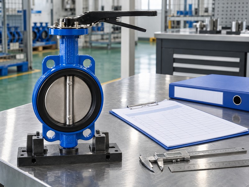
A tamper switch on butterfly valve arrangement can be affected by damaged leads, compromised entries, moisture exposure or physical interference. Document accessible external condition against the selected installation requirements. An enclosure designation cannot establish that an installed gland, conduit connection or junction box preserves the protection required for that location.
Which observations help without opening the housing?
Describe accessible external conditions. Record visible damage, loose external fittings, unsupported cable, moisture signs and blocked access where observation is authorized. Photographs can locate a concern but cannot reveal concealed contacts or prove enclosure integrity. Authorized personnel must follow selected procedures for housing access and corrective work, retaining actual exposure conditions in the report.
- Record visible lead, entry and enclosure concerns.
- Compare exposure and routing with selected installation requirements.
- Refer concealed-condition investigation through the authorized work procedure.
Key takeaway: Use external observations to define the investigation without claiming that photographs prove internal condition.
| Check | What you should confirm |
|---|---|
| External | Accessible damage or interference is recorded accurately |
| Environment | Actual exposure is compared with the selected arrangement |
| Access | Inspection and correction follow the permitted work method |
7. How is a tamper switch on butterfly valve observed?
Observe a tamper switch on butterfly valve through an authorized test that compares the required valve position, selected contact response and corresponding system report. Define the expected results before moving the valve or disturbing its circuit. Use the identified product and approved project criteria for every acceptance decision.
What belongs in the change-and-restoration record?
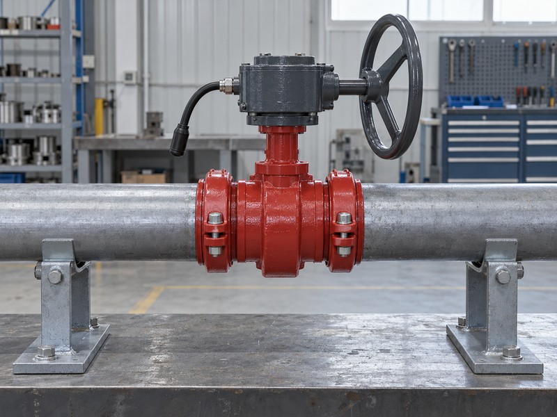
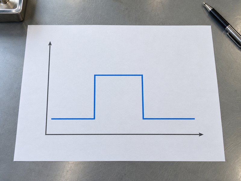
Compare recorded conditions. Retain the initial physical position and report, required departure response, approved corrective work and restored condition. Record acceptance limits from the actual selected documents, since a generic turn count, angle or elapsed time cannot establish a passing result. The abstract chart shows initial, changed and restored states only; its levels and spacing define no polarity, electrical value or measured response.
- Identify the valve, monitored input and expected event text.
- Record required state changes under the approved test procedure.
- Confirm the required physical and system conditions after restoration.
Key takeaway: Base restoration on recorded physical and reporting evidence against the approved criteria.
| Check | What you should confirm |
|---|---|
| Initial | Required position and associated report are recorded |
| Changed | Specified departure produces the required response |
| Restored | Actual valve and system states meet the accepted requirements |
8. When can a tamper switch on butterfly valve need replacement?
A tamper switch on butterfly valve may need replacement when an authorized investigation identifies a defect that the selected instructions address through replacement. Match the actual assembly and permitted parts before purchasing. A spare switch with similar contacts cannot establish compatible mounting, approved supervisory use or preservation of the assembly’s required approval.
Which configuration changes need another review?
Identify the approved replacement. Check the manufacturer’s specified kit or assembly, operator orientation, interfaces and applicable approval coverage against the installed configuration. Supervisory and auxiliary contacts can have different permitted uses, so an unused auxiliary contact cannot become a generic replacement for the designated supervisory function. Retain the replacement record and repeat affected mechanical, electrical and reporting checks under the authorized procedure.
- Record the diagnosed defect and selected replacement identity.
- Verify compatibility and permitted supervisory function.
- Review changed interfaces and repeat affected acceptance checks.
Key takeaway: Purchase replacements from an identified technical basis and preserve their configuration and test records.
| Check | What you should confirm |
|---|---|
| Part | Replacement matches the identified manufacturer’s arrangement |
| Function | Designated supervisory use remains supported |
| Verification | Affected mechanical and electrical functions receive renewed checks |
9. Who may test a tamper switch on butterfly valve?
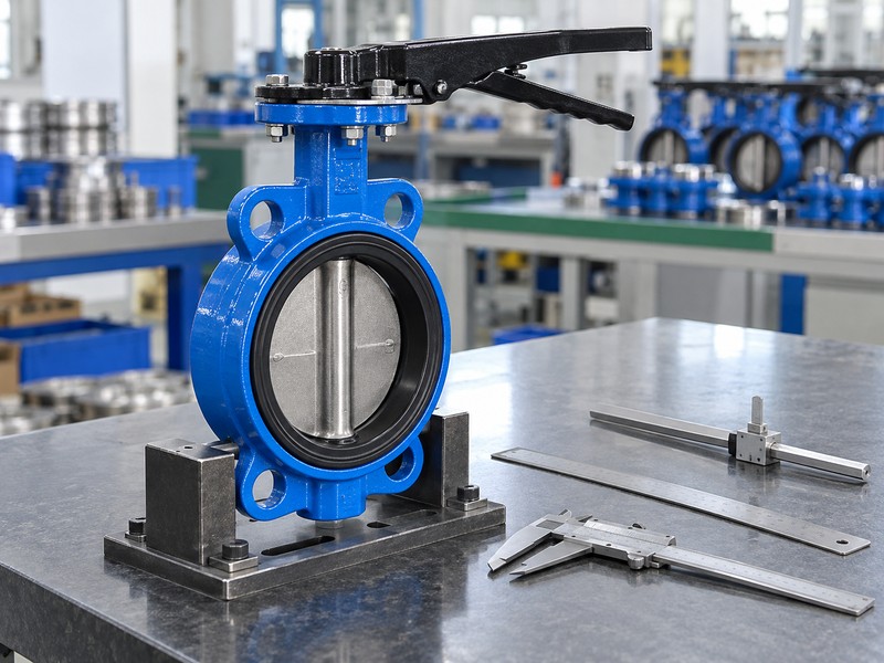
Personnel authorized under the project’s requirements may test a tamper switch on butterfly valve using the selected procedures and assigned responsibilities. Identify who controls valve movement, system work and restoration before starting. A troubleshooting article cannot authorize an impairment, shutdown or change to a fire-protection system.
What should the work plan settle before physical testing?
Assign the work boundaries. Identify affected protection, required permissions, notifications, isolation arrangements and restoration evidence in the approved work plan. Coordinate mechanical and fire-alarm personnel where their observations or actions depend on each other. Derive inspection tasks, frequency, test criteria and corrective actions from applicable adopted requirements and selected instructions.
- Identify authorized personnel and affected system functions.
- Follow required impairment, isolation and notification procedures.
- Assign restoration checks and acceptance responsibility before work.
Key takeaway: Authorize and coordinate the work before performing any action that affects protection or reporting.
| Check | What you should confirm |
|---|---|
| Authority | Required permission and personnel roles are established |
| Scope | Affected protection and planned actions are identified |
| Restoration | Responsible parties agree on evidence and closure requirements |
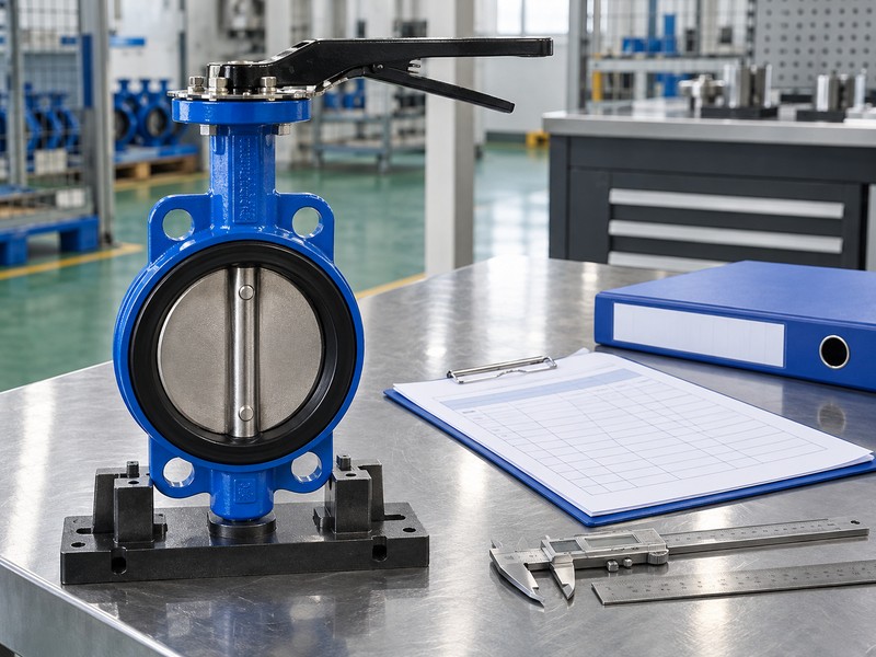
10. What closes a tamper switch on butterfly valve service record?
Close a tamper switch on butterfly valve service record when the responsible parties accept the diagnosed condition, approved correction and required restoration evidence. Identify the final physical position and corresponding system report. A record that says only reset or replaced cannot explain what failed, whether configuration changed or which functions were verified.
What should remain available for the next service visit?
Retain the accepted findings. Keep asset identity, observed events, technical findings, approved parts, revised documents and test results linked to the same work record. Distinguish a verified correction from an intermittent symptom that could not be reproduced, recording any required follow-up through the owner’s process. RUITO can review an identified valve-assembly request and available documents; responsible project professionals retain system diagnosis, design, commissioning and acceptance duties.
- Link the diagnosis and correction with the actual asset.
- Retain replacement identities and affected verification results.
- Document unresolved findings and assigned follow-up responsibility.
Key takeaway: Leave a service record that explains the observed condition, accepted correction and verified restoration.
| Check | What you should confirm |
|---|---|
| Finding | Observed condition and technical diagnosis are distinguished |
| Correction | Approved work and changed components are traceable |
| Closure | Restoration evidence and unresolved actions have assigned owners |
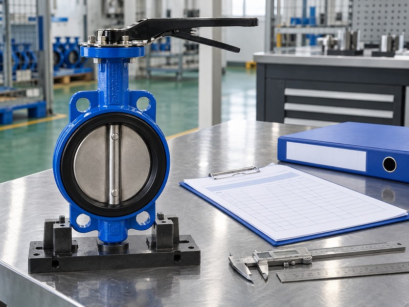
Send RUITO the identified valve-assembly request, operator details, relevant photographs and available product documents when your team needs a product-configuration review. We can review those materials and identify the valve documents still needed. Contact us before purchasing a replacement whose identity or compatibility remains unresolved in the service record.
FAQ
Q1: Can I close the work order when the panel clears?
Only when required restoration evidence is accepted. Confirm the physical position, correct point response and applicable test results through the approved procedure.
Q2: What’s the best information to send with a fault report?
Send an identifiable condition record. Include valve and operator labels, exact event text, point identity, chronology and accessible external observations.
Q3: How do I know if a report concerns the correct valve?
Verify the asset-to-point relationship. Compare installed identification and authorized test evidence with the accepted zone, input or address schedule.
Q4: Can I use an unused auxiliary contact as the replacement?
Only with explicit support for that configuration. Auxiliary and supervisory contacts can have different lead arrangements and permitted uses.
Q5: How do I know if a normal signal proves water is available?
It does not prove supply. Position supervision and hydraulic performance require separate evidence for their respective functions.