
Test an electric operated butterfly valve by confirming mechanical readiness, then verifying actual travel, controls and feedback through the agreed safe sequence. If a new unit stops halfway through its stroke, repeated commands can hide a mechanical problem or damage the drive. Check readiness, prove each control function and record the result before the process depends on that valve.
1. What must an electric operated butterfly valve test prove?
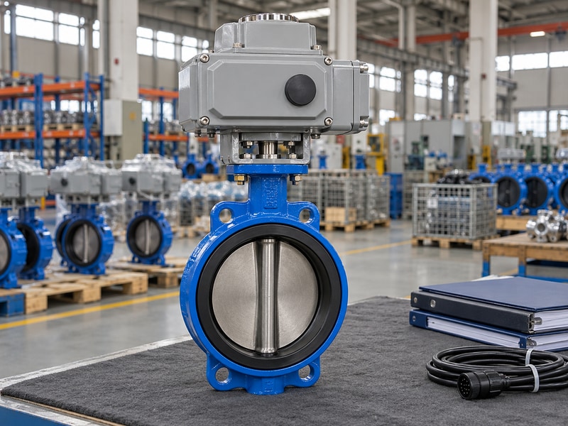
An electric operated butterfly valve test must prove actual valve movement, correct control priorities and dependable indication for the agreed duty. A motor sound or moving pointer proves only part of the sequence. Start by defining which observations will establish that the complete package has passed.
Write the acceptance sequence before energizing
Separate receipt inspection, mechanical readiness, electrical checks and functional testing. Record who may authorize each stage and who may stop the test. A dry bench check does not reproduce hydraulic loading. A valve pressure test does not verify remote commands. Keep those limits visible in the test sheet so a successful preliminary check cannot become an unsupported claim of full process performance.
Use the approved data sheet, assembly drawing, terminal diagram and installation instructions for the exact unit. Record identification and revisions before starting. If an actuator has been replaced since factory testing, the assembly deserves another interface review. Compare the supplied arrangement with RUITO’s butterfly valve configurations and resolve discrepancies before accepting the package.
- Identify the unit and document revisions.
- Define the observed pass criteria.
- Separate preliminary checks from loaded performance.
| Stage | Observation | Record |
|---|---|---|
| Receipt | Correct supplied configuration | Identification and condition |
| Functional test | Commands produce intended movement | Sequence and actual positions |
| Handover | Approved settings and documents | Signed final revision |
2. Which mechanical checks come before powered travel?
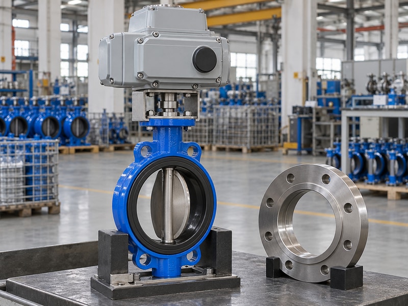
Inspect an electric operated butterfly valve for disc clearance, flange alignment and secure drive engagement before powered movement. A blocked disc can make a sound actuator appear faulty. Electrical troubleshooting will not correct a companion flange or pipe bore that obstructs the disc’s opening envelope.
Remove the load caused by installation errors
Confirm the approved flange standard, bore, face arrangement and face-to-face dimension. Check gasket requirements from the valve instructions. An integral resilient seat may form the joint seal without added gaskets, while other constructions have their own requirements. Pipe supports must carry their intended loads; tightening flange bolts should not pull misaligned pipework into place through the valve body.
Review bracket fasteners and the coupling without reaching into a movement zone. Follow the prescribed safe method for checking travel. If mechanical disconnection is required, isolate all energy sources and control stored energy before work begins. A comparison with the wafer valve installation arrangement helps identify the compact body’s disc-clearance requirements.
- Confirm flange bore and opening clearance.
- Follow the specified gasket arrangement.
- Check the drive fit under safe isolation.
| Mechanical item | Possible symptom | Resolve before power |
|---|---|---|
| Disc interference | Stops at repeatable angle | Correct bore or fit |
| Flange strain | High travel load | Align and support pipework |
| Loose coupling | Indicator moves without disc | Restore approved engagement |
3. How do you confirm electrical readiness?
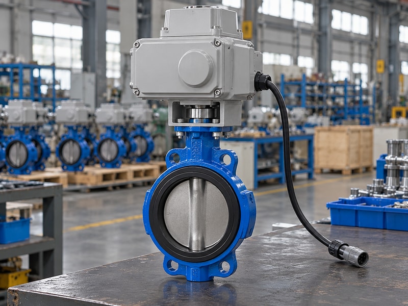
Electrical readiness for an electric operated butterfly valve means the supplied voltage, protective arrangement, commands and feedback match the selected actuator’s drawing. Keep motor power and control signals separate in the check sheet. A controller’s low-voltage output cannot be assumed to power the actuator motor.
Use the delivered unit's terminal drawing
Qualified personnel should verify the supply and wiring using the approved installation procedure and local electrical practices. Identify protective earth, isolation, cable entries and required protection. Confirm whether each control input expects a dry contact, switched voltage or another interface. Check the receiving system’s input against the actuator output type and contact ratings before connecting feedback.
Do not transfer terminal numbers from a similar actuator. Record the model, supply option and drawing revision actually used. Check enclosure closures and entry seals after wiring work. An outdoor rating does not settle condensation requirements, and ordinary weather protection does not establish hazardous-area suitability. Resolve any difference between the ordered enclosure and site conditions before continuing.
- Verify power and signals separately.
- Check feedback output and input compatibility.
- Restore enclosure and cable-entry protection.
| Check | Evidence | Reason to pause |
|---|---|---|
| Supply | Selected actuator data | Voltage or arrangement mismatch |
| Commands | Exact terminal drawing | Unclear input type |
| Feedback | Output and receiving ratings | Incompatible interface |
4. How should local operation be checked?
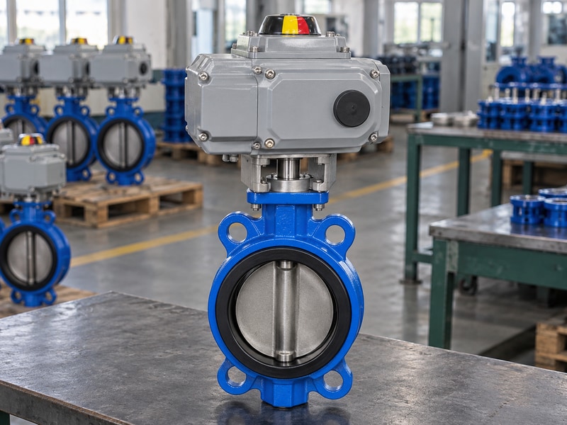
Check an electric operated butterfly valve locally through the approved sequence while observing actual travel and endpoint indication. Use a safe test condition with a controlled movement area. Confirm which local mode is selected and whether remote commands are permitted or inhibited in that mode.
Record direction, stops and indication together
Command the specified movement and compare the actual valve position with the indication. Record travel time, smoothness, stop behavior and any fault indication required by the procedure. Unexpected vibration, repeated stopping or a mismatch between the disc and pointer requires investigation. Repeatedly overriding the fault can turn an identifiable problem into damage and make the original condition harder to reconstruct.
Check the manual operating arrangement only according to its instructions. Some mechanisms require a defined engagement procedure or interlock. Do not attach a lever to increase force or assume that hand operation bypasses all electrical hazards. After the local check, restore the approved mode and record any setting adjustment, its reason and the person who authorized it.
- Confirm the selected operating mode.
- Compare actual position with indication.
- Record faults before altering settings.
| Observation | Expected basis | If different |
|---|---|---|
| Movement direction | Approved command sequence | Check orientation and controls |
| Stopping point | Specified travel limits | Review limits and interference |
| Position indication | Validated actual position | Check linkage and feedback |
5. How do remote commands and feedback get verified?
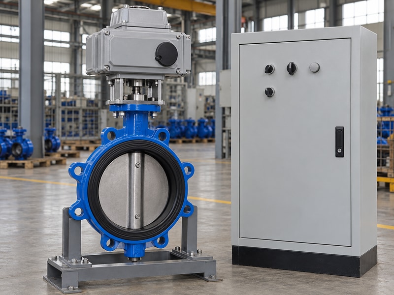
Verify an electric operated butterfly valve from the actual remote control point and compare each command with the valve’s observed response. A successful local check does not establish remote wiring, software mapping or control priority. Trace the same valve identification through the field unit and receiving system.
Keep command and returned position distinct
Start with the agreed permissives and mode selection. Confirm that the remote open command reaches the intended valve and that the returned position represents that valve. A screen displaying the last command can look like feedback while providing no evidence of movement. Define whether indication comes from endpoint switches, a position transmitter or another validated source.
Check conflicting-command handling and the priority between local, remote and maintenance modes where the design requires it. Include interlocks under the authorized test plan rather than forcing an operating process into an unsafe state. For a water project, the service description on RUITO’s water treatment application page can support the duty discussion; the project control narrative still governs the sequence.
- Match field and control-system identification.
- Observe movement independently of the command.
- Verify required permissives and priorities.
| Signal | What it means | How to prove it |
|---|---|---|
| Open command | Request for movement | Trace and observe response |
| Open feedback | Defined position condition | Compare with actual travel |
| Fault output | Specified abnormal condition | Approved fault test |
6. What changes for a modulating actuator?
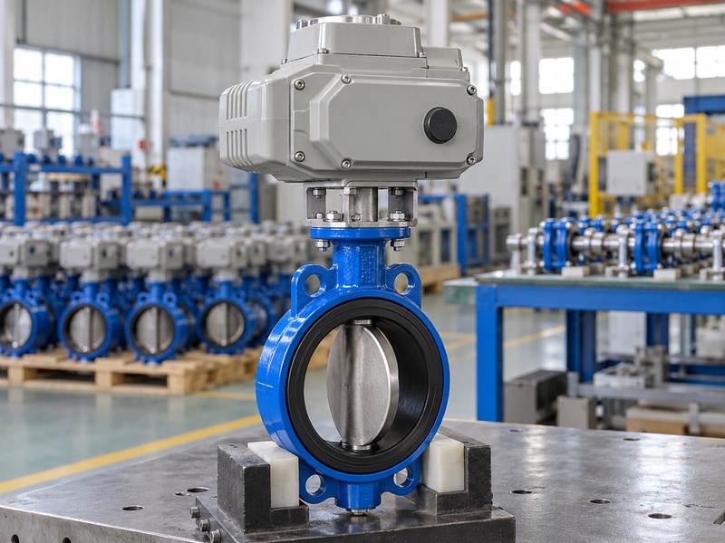
A modulating electric operated butterfly valve needs positioning checks as well as endpoint checks. Verify requested travel, returned position and stable response at agreed test points. Passing a full-open and full-close test does not prove that the valve can hold intermediate positions or tolerate the required positioning duty.
Test the position loop without inventing a flow curve
Use the configured command range and feedback range for the delivered unit. Compare several specified positions in both travel directions and record the permitted tolerance. Check the effect of deadband and any minimum movement setting against the control requirements. Rapid hunting deserves investigation into the loop and process conditions; changing actuator settings without a record can conceal the cause.
Keep dry position testing separate from flow performance. At a given disc angle, flow depends on the valve characteristic and system conditions. A controlled-flow objective needs the appropriate measurement and loop verification. Confirm actuator duty and starts against the intended service before extended cycling, particularly if the test itself could exceed the permitted operating duty.
- Use the configured signal range.
- Check intermediate positions in both directions.
- Keep travel percentage separate from flow percentage.
| Test item | Compare | Acceptance source |
|---|---|---|
| Travel request | Command against actual position | Approved control specification |
| Position stability | Settling and hunting | Agreed test criteria |
| Duty | Movement and starts | Selected actuator rating |
7. How should loss responses be tested?
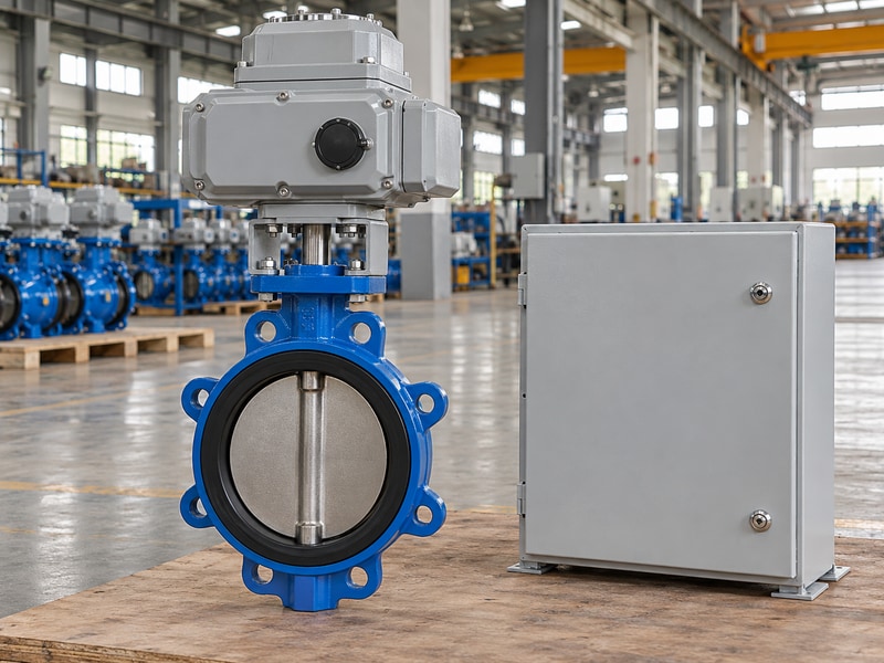
Test an electric operated butterfly valve loss response against the specified event, available energy and required final state. Power failure, command failure and communications failure are separate conditions. A valve that holds position during one event may move during another because the control package handles them differently.
Include restoration in the test plan
For a package with stored energy, review the conditions under which that energy is available and the load it must overcome. Specify how the test represents the required response without creating a process hazard. Record actual movement and indication rather than inferring the outcome from a configured menu. A reserve module’s presence does not prove the assembly will complete its required stroke.
Check what happens when power or communication returns. The system may require reset, retain local control or respond to a standing command, depending on the approved design. The test record should identify that behavior. Obtain authorization before fault simulation on installed equipment and restore the agreed operational state when testing ends.
- Test each required loss event separately.
- Observe the actual final state.
- Check reset and restoration behavior.
| Event | Test observation | Record afterward |
|---|---|---|
| Power loss | Hold or required movement | Final position and time |
| Signal loss | Configured failure behavior | Actual response |
| Restoration | Approved restart sequence | Reset and operating mode |
8. How do you investigate a failed travel check?
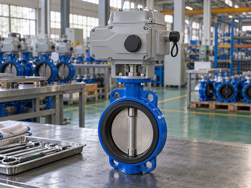
Investigate an electric operated butterfly valve fault by recording the exact sequence and separating mechanical, electrical and control causes. Stop repeated commands when the unit stalls or trips. The point where motion stopped, selected mode and feedback state usually provide more useful evidence than a general description such as ‘the valve failed’.
Preserve evidence before changing the unit
Record product identification, command, observed position, fault indication and recent work. Under safe isolation, check installation clearance and mechanical engagement according to the instructions. Have qualified personnel verify supply and control conditions. A low-voltage problem, pipe strain and a misconfigured travel limit can produce similar visible symptoms while requiring different corrective actions.
Do not raise torque protection to force a blocked valve through its stroke. Do not dismantle the seat or drive before considering warranty and inspection requirements. RUITO’s support team uses identification, photos, medium, operating conditions and installation records to assess a complaint. Retain removed parts and setting records so an engineering review can reconstruct the supplied and failed conditions.
- Record the first observed fault sequence.
- Check causes under safe isolation.
- Authorize and document every setting change.
| Symptom | Possible area | Useful evidence |
|---|---|---|
| No movement | Supply or command | Mode, voltage and signal record |
| Stops at one angle | Interference or settings | Travel position and installation |
| Wrong indication | Feedback or coupling | Actual position comparison |
9. What belongs in the commissioning handover?
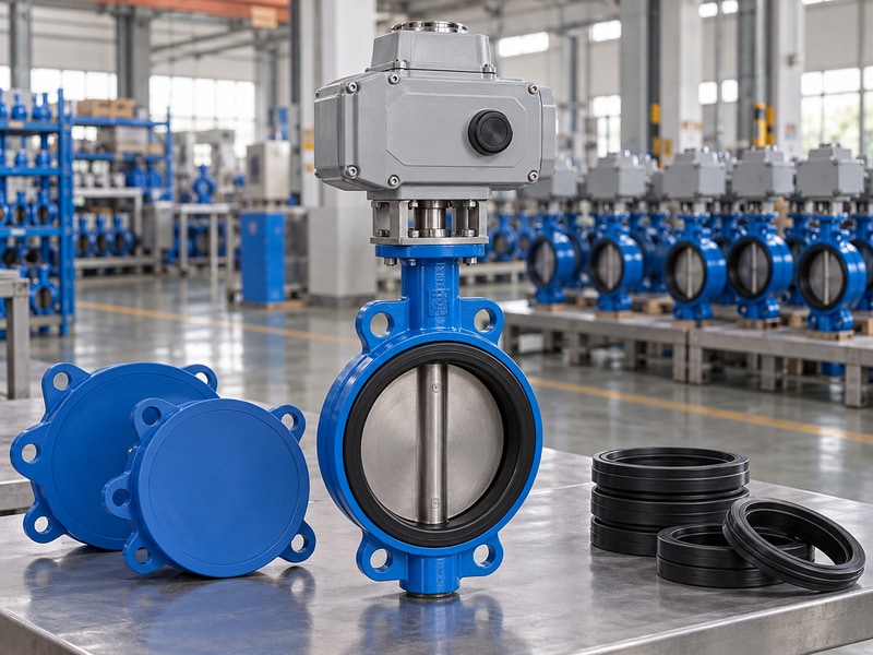
An electric operated butterfly valve handover should preserve the final configuration, settings, test results and unresolved items. A signed sheet saying ‘works’ leaves the maintenance team without a usable baseline. Record what was checked, under which conditions and which observations supported acceptance.
Give maintenance a repeatable starting point
Keep final drawings, actuator data, terminal information and installation instructions together. Include position and limit settings, control ranges where applicable, test instruments and the actual package identification. Record deviations and approved corrective actions. If a test was deferred, name the remaining test and its acceptance authority instead of leaving a blank line that could be mistaken for a pass.
Set storage or inspection actions for equipment that will wait before operation. Confirm spare-part identification against the approved material list and record the manual operating procedure. Use the RUITO technical enquiry route when a delivered configuration needs clarification. Future replacements should be reviewed against this baseline, including the control interface and required loss response.
- Keep the final drawing and settings together.
- Name deferred tests and open deviations.
- Link spare parts to the approved configuration.
| Handover item | Include | Future use |
|---|---|---|
| Configuration | Identification and revisions | Replacement review |
| Settings | Limits, ranges and mode | Troubleshooting baseline |
| Test record | Conditions and observations | Repeatable verification |
RUITO can review the supplied valve configuration, drawing revisions and agreed test records with your commissioning team. Send the product identification, duty sheet and observed fault sequence. Contact us before changing torque protection or dismantling a unit that has stopped during travel.
10. What else should you check before ordering?
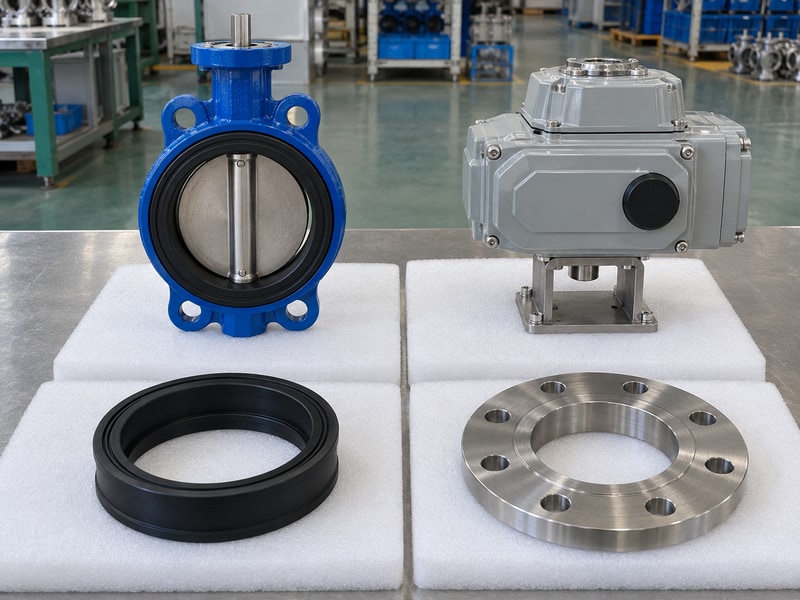
For electric operated butterfly valve, resolve these remaining questions against the approved package and site conditions.
Q1. Can I commission the actuator before installing the valve?
You can perform authorized preliminary checks, but they do not prove the final installed assembly. Repeat the required mechanical, command and feedback checks after installation, and complete the agreed loaded checks separately.
Q2. What's the best response to a torque trip?
Stop repeated commands and record the fault sequence. Check the cause under safe isolation. Raising torque protection without engineering approval can damage the shaft, coupling, seat or actuator.
Q3. How do I know if feedback is real?
Compare the reported condition with an independently observed or otherwise validated valve position. A displayed command or animated screen symbol alone does not establish actual disc movement.
Q4. Can I use the same test sheet for on-off and modulating units?
Use a shared identification section, then add the tests specific to each control function. Modulating packages need intermediate positioning, range and stability checks that endpoint testing does not cover.
Q5. What should I report when the valve stops halfway?
Report identification, drawing revisions, command, mode, actual position, indication, fault messages and recent work. Include operating conditions and photos taken safely. Preserve settings before making any authorized changes.