
Choose an electrically operated butterfly valve by matching its wetted materials, valve load and control function to the actual process duty. If your pump runs while the valve reports the wrong position, the problem may lie in drive alignment, feedback or selection. Start with the complete assembly: the valve, actuator, controls and actual process duty must agree.
1. How does an electrically operated butterfly valve work?
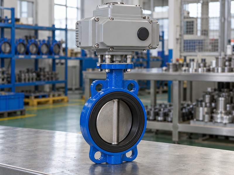
An electrically operated butterfly valve turns its shaft and disc through a nominal quarter turn, using an electric actuator mounted above the valve. With the disc across the bore, its edge engages the seat. With the disc aligned along the pipe, fluid passes around it; the disc and shaft still occupy some flow area.
Follow the mechanical load path
Motor speed passes through reduction gears before reaching the output drive. A coupling transfers that rotation into the valve shaft. The bracket supports the actuator and keeps the two axes aligned. A loose coupling can let the position indicator move while the disc remains partly closed, so an indicator alone cannot prove that the complete load path is intact.
Compare the approved assembly drawing with the supplied unit. Check mounting holes, drive shape, coupling engagement and clearance around the enclosure. On a bench, verify the disc position against the indicator using the manufacturer’s safe procedure. For the available body arrangements, review RUITO’s butterfly valve range before choosing a connection.
- Identify the valve and actuator separately.
- Check coupling engagement and bracket fasteners.
- Compare actual disc travel with indicated travel.
| Part | Job | Check |
|---|---|---|
| Motor and gears | Produce rotary output | Approved duty and supply |
| Coupling and shaft | Transmit torque | Fit and engagement |
| Disc and seat | Control and isolate flow | Travel and sealing contact |
2. Which body and seat arrangement suits the medium?
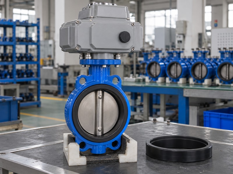
Choose an electrically operated butterfly valve by its wetted materials and process conditions before selecting the motor. Clean water, mineral oil and acid dosing need different seat and material assessments. A matching pipe size does not establish chemical compatibility, allowable temperature or suitability for a particular fluid.
Keep each material configuration intact
For RUITO’s conventional water configuration, the documented construction uses a ductile iron body, CF8M disc, approved stainless shaft and EPDM seat. NBR oil configurations have their own material definition. Lined chemical valves require the liner, disc covering, backing and shaft seals to work together. A corrosion-resistant disc cannot protect an exposed shaft or an incompatible backing material.
Ask for the material list for the exact unit, including coatings and auxiliary seals. Give the supplier concentration, cleaning chemicals, solids and operating temperature. If the service requires a continuous chemical barrier, compare the relevant PTFE lined butterfly valve configuration with the complete fluid description. Do not substitute a seat based only on its generic polymer name.
- Provide the full medium composition.
- Include cleaning and upset conditions.
- Approve all wetted parts together.
| Service | Material question | Approval basis |
|---|---|---|
| Clean water | EPDM and coating compatibility | Exact water configuration |
| Mineral oil | NBR and additives | Approved oil formulation |
| Chemical liquid | Continuous isolation of wetted parts | Complete lined assembly |
3. How do pressure and temperature limit selection?
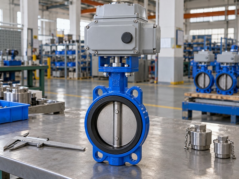
Rate an electrically operated butterfly valve for pressure and temperature together, using the selected valve’s documented operating envelope. PN identifies a pressure class; it does not promise the same allowable pressure at every temperature. The seat, body, connection and direction-specific shutoff rating can impose different limits.
Separate operation from pressure testing
RUITO documents conventional water-duty wafer valves within their own size and pressure ranges. A test report may show a higher pressure than the service rating because shell and closure tests verify defined conditions. That test pressure must stay in the inspection record. Copying it into the operating data sheet would give the system designer a false working limit.
Define normal pressure, maximum pressure, closing differential and transients separately. The pressure difference across a closing disc affects torque and seat duty even when upstream pressure remains unchanged. Ask which direction the shutoff rating covers. For larger double-offset assemblies, obtain both directions explicitly rather than transferring a small concentric valve’s assumptions to a different design.
- Use one approved pressure-temperature envelope.
- State closing differential separately.
- Keep test pressures out of operating ratings.
| Value | Meaning | Where it belongs |
|---|---|---|
| Operating pressure | Permitted service condition | Approved data sheet |
| Closing differential | Load across the disc | Torque and seat review |
| Test pressure | Inspection condition | Signed test report |
4. How should you match actuator torque?
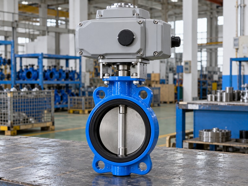
Match an electrically operated butterfly valve actuator against the valve’s required torque over the complete stroke. Breakaway, running and seating loads can differ. Required torque also changes with differential pressure, seat material, fluid conditions and time out of service; pipe diameter alone cannot determine the actuator size.
Check the lower and upper limits
Use the valve supplier’s torque data and the actuator manufacturer’s output data at the stated supply and environmental conditions. Apply the agreed design allowance without inventing a universal multiplier. Then check the permissible input torque of the shaft, coupling, mounting hardware and valve. A larger motor can overload those parts if its limiting settings or stall output exceed their capacity.
For an illustrative worksheet, a 120 Nm requirement with an agreed 25% allowance becomes 150 Nm. That arithmetic does not qualify an actuator: its usable output, duty, speed and torque protection still need review. Record the selected limit settings and responsibility for setting them. Keep that worksheet with the approved assembly drawing rather than relying on a catalog torque label.
- Obtain the valve torque requirement.
- Document the allowance and usable actuator output.
- Check the assembly’s maximum permitted input.
| Torque item | Question | Required evidence |
|---|---|---|
| Required torque | What does the valve need? | Duty-specific valve data |
| Available output | What can the actuator deliver? | Selected actuator data |
| Permitted input | What can the assembly withstand? | Approved mechanical limits |
5. When do you need on-off or modulating control?
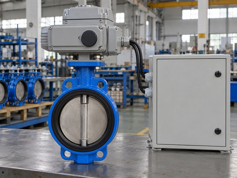
Use an electrically operated butterfly valve with on-off control for isolation and an approved modulating package for intermediate positioning. A motor that reaches both endpoints may still be unsuitable for repeated small corrections. Specify the control behavior, movement frequency and process response before deciding which actuator to buy.
Distinguish position from flow
Position control holds a requested disc angle. Flow control needs a process measurement and a control loop that commands the valve. A 50% travel signal does not mean 50% flow, because flow depends on the valve characteristic and pressure distribution through the system. Ask for the selected valve’s capacity data when evaluating a throttling application.
Check permitted starts, duty and positioning behavior against the actual control sequence. Include minimum movement, deadband and required feedback in the package specification. A simple cooling-water isolation valve and a continuously adjusted process valve may have similar bodies while needing different drives. RUITO’s HVAC application information can help establish the service context before the detailed control review.
- Write the control function in plain terms.
- State the expected movement frequency.
- Use process feedback for a flow-control objective.
| Function | Command | Acceptance observation |
|---|---|---|
| Isolation | Open or close | Correct endpoint and indication |
| Positioning | Requested travel | Stable actual position |
| Flow control | Process loop output | Measured process response |
6. What must the electrical interface define?
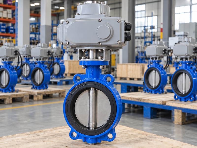
The electrical interface for an electrically operated butterfly valve must identify power supply, commands, feedback and protective connections separately. A 24 V control signal does not establish the actuator’s motor voltage. Terminal numbers and wiring methods must come from the drawing for the exact supplied actuator.
Approve the drawing before site wiring
Provide voltage, frequency where applicable, supply arrangement and the available electrical protection. Confirm whether commands use switched power, dry contacts or an analogue interface. Check whether feedback contacts are powered or voltage-free and whether their ratings suit the receiving equipment. Similar terminal layouts on two models do not make their circuits interchangeable.
Include cable entry requirements, enclosure conditions and access for maintenance. Outdoor moisture, condensation, washdown and a hazardous area are separate specification questions. An enclosure rating alone does not establish explosion protection. Have qualified personnel connect and test the package against the approved instructions, with isolation and local site procedures in place.
- Separate supply and signal requirements.
- Match feedback to the receiving input.
- Use the exact approved terminal drawing.
| Interface | Define | Avoid assuming |
|---|---|---|
| Power | Voltage and supply arrangement | Control voltage equals motor voltage |
| Commands | Signal type and priority | Shared wiring across models |
| Feedback | Contact or analogue output | Indicator equals verified position |
7. What happens after a loss of power or signal?
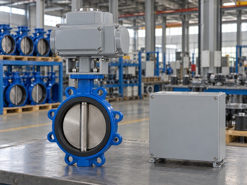
An electrically operated butterfly valve moves after power loss only if the selected package has a verified means of doing so. Ordinary electric actuation does not automatically provide fail-close behavior. Power loss, signal loss and communication loss can produce different responses and must each have an agreed outcome.
Specify the event and the required response
Stored spring energy, a suitable electrical reserve or another engineered arrangement may provide movement to a defined position. Its availability, torque, duration and maintenance conditions belong in the approval. The required position comes from the process risk assessment. Closing may protect one system while interrupting cooling in another, so the valve supplier needs the intended sequence.
Write an acceptance step for each relevant event and for restoration of supply. Check whether a returning command causes immediate movement, requires reset or remains under local control. Do not demonstrate fault responses on an operating process without an approved test plan. Observe actual disc or validated position feedback and retain the results for the supplied assembly.
- Define each loss event separately.
- Identify the energy available for movement.
- Agree on reset and restart behavior.
| Event | Specify | Verify |
|---|---|---|
| Power loss | Hold or move to a defined state | Complete package response |
| Signal loss | Local configured action | Actual travel and indication |
| Power restored | Reset and command priority | Controlled restart sequence |
8. How do installation and storage affect operation?

Protect an electrically operated butterfly valve from flange strain, disc interference and moisture before commissioning. The actuator cannot correct a valve body pulled out of alignment by the pipework. Storage damage or an obstructed disc may appear as a torque fault after the unit reaches the installation site.
Check the mechanical fit before energizing
Verify companion flange bore, face arrangement and disc opening envelope from the approved drawing. Follow the valve’s gasket instructions; adding a separate gasket to an integral elastomer seat can create a poor joint or distort the seat. Support the pipe and assembly as specified. Never use the actuator housing as a lifting point unless the instructions expressly permit it.
Keep openings protected and store the unit under the stated environmental conditions. Confirm the required storage position, enclosure sealing and inspection interval. Before powered travel, remove packing obstructions and check the mechanical arrangement using the safe installation procedure. Review the wafer body connection details where a compact between-flange installation is proposed.
- Check the complete disc opening envelope.
- Follow model-specific gasket instructions.
- Protect bore openings and electrical entries.
| Risk | Check | Action before operation |
|---|---|---|
| Disc contact | Pipe and flange bore | Resolve interference |
| Seat distortion | Faces, gaskets and tightening | Follow approved installation |
| Moisture ingress | Storage and cable entries | Restore specified protection |
9. What should package acceptance prove?
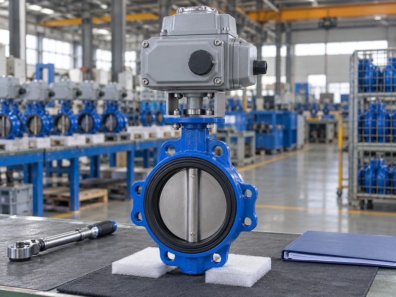
Acceptance of an electrically operated butterfly valve should prove the agreed valve performance and the integrated drive behavior. A loose actuator test cannot establish the assembled valve’s travel, direction or feedback. Keep pressure tests, electrical checks and functional tests identifiable so each result has a clear purpose.
Keep the evidence tied to the supplied unit
Agree on the inspection plan before production. Identify the selected pressure test standard, applicable seat criterion, test direction and required records. For the integrated package, include local and remote commands, endpoint indication, intermediate positioning where specified and the agreed loss responses. Use calibrated instruments and suitable fixtures under the approved procedure rather than inventing a field test pressure.
Ask for the final material list, assembly drawing, actuator data, terminal diagram, instructions and test records linked to the product identification. Confirm that the settings recorded on those documents match the delivered unit. RUITO can review these requirements with the duty sheet; a request for a particular size and voltage alone leaves too much of the assembly undefined.
- Freeze the inspection and test scope.
- Verify assembled travel and feedback.
- Receive the final approved document versions.
| Evidence | What it establishes | Match to delivery |
|---|---|---|
| Pressure report | Specified valve test result | Product identification and direction |
| Functional record | Integrated operation | Actual actuator and settings |
| Final document pack | Installation and maintenance basis | Approved revisions |
Send RUITO your medium, operating pressure and temperature, maximum closing differential, flange details and control requirements. We can review the assembly against those inputs and identify the documents needed for approval. Contact us with the duty sheet before you approve a motor size or release an order.
10. What else should you check before ordering?
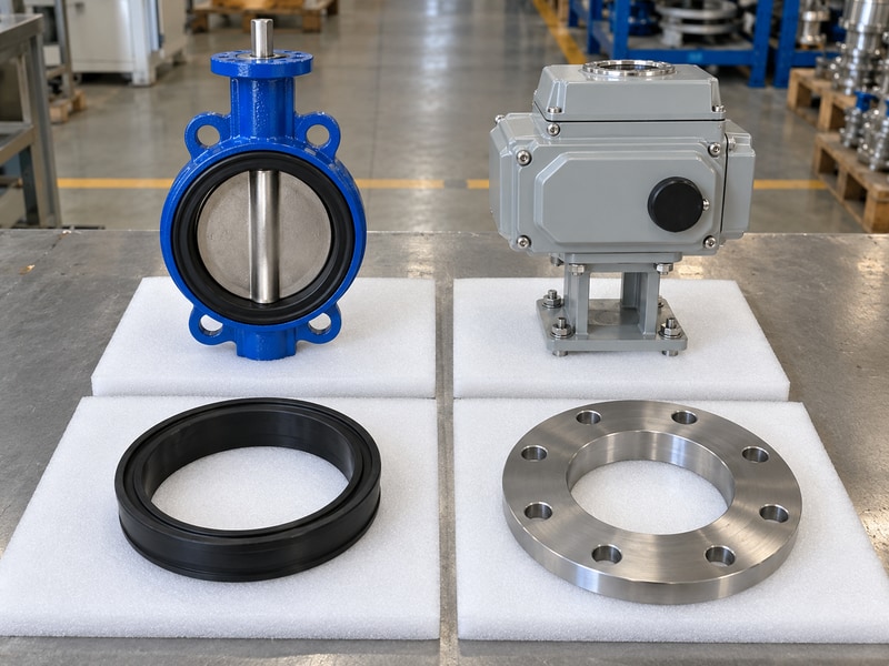
For electrically operated butterfly valve, resolve these remaining questions against the approved package and site conditions.
Q1. Can I use any quarter-turn electric actuator?
No. Match required torque, maximum permitted input, drive fit, travel, duty and controls. A matching mounting flange covers only part of that assessment. The complete assembly needs approval for the stated process conditions.
Q2. Will the valve close if power fails?
Only when the specified package provides and verifies that response. Define power loss and signal loss separately. Confirm the available energy, actual valve load and restart sequence before treating the valve as fail-close.
Q3. Can I use disc angle as a flow reading?
No. Disc angle indicates position. Flow also depends on the valve characteristic and system pressure conditions. Use suitable flow measurement and an approved control loop when the process needs a controlled flow rate.
Q4. How do I know whether the seat suits my fluid?
Check the complete material configuration against fluid composition, concentration, temperature and cleaning conditions. The seat name alone cannot qualify the disc, shaft, backing materials or auxiliary seals for that service.
Q5. What should I send with an enquiry?
Send the fluid details, operating envelope, flow and differential pressure, connection drawing, supply, control function and required failure response. Add inspection and document requirements so the quotation covers a reviewable complete package.