
Choose an actuator gearbox by checking the output motion, input limits and the way manual operation interacts with the normal drive. A gearbox can adapt torque and speed, but it also adds interfaces and operating steps. Confirm the complete valve-and-drive arrangement before treating a separate manual unit as a compatible override.
Images are AI-generated illustrations of generic equipment configurations.
1. What does an actuator gearbox add?
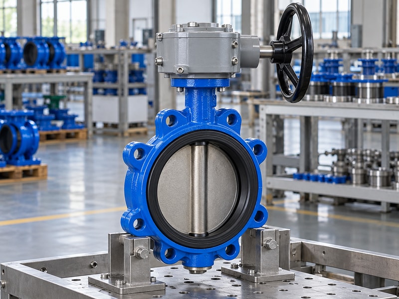
An actuator gearbox changes input motion before delivering it to a valve or another driven mechanism. It can provide reduction, redirect a drive or form part of an approved manual-operation arrangement. The added gearbox must suit the actual output function and the input source, with its own ratings included in the package review.
What must the additional mechanism accomplish?
State whether you need more manageable manual effort, a different input position, added reduction or an override for a powered valve. These are different requirements and may lead to different mechanisms. A separate gearbox also adds shaft connections, mounting faces and possible losses. Compare the complete arrangement with the original duty, including travel, operating time and access, so the extra mechanism solves a defined problem without creating an unreviewed limitation elsewhere in the drive.
- State the reason for adding the gearbox.
- Identify normal and alternate operating modes.
- Review the complete drive after the addition.
Key takeaway: Select the gearbox by the function it adds to the assembled equipment.
| Check | What to confirm |
|---|---|
| Mechanical function | Reduction, direction change or output adaptation. |
| Operating function | Manual provision or another approved drive mode. |
2. Which valves need part-turn output?
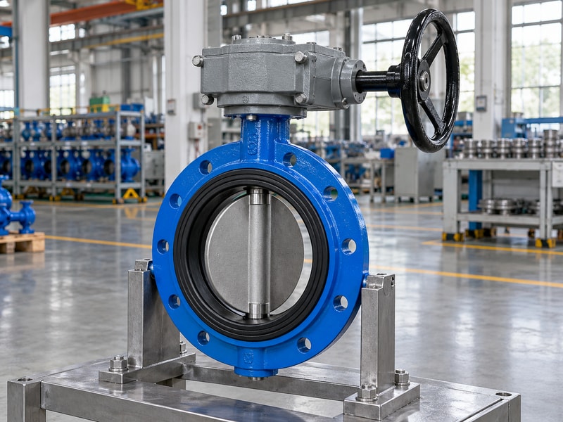
A part-turn actuator gearbox suits a valve whose output needs limited-angle rotation, such as a suitable butterfly, ball or plug valve. Confirm the required angle and seating method for the exact valve. A nominal quarter-turn description does not identify the coupling orientation, stop settings or allowable operating torque.
Which travel details need agreement?
Record the physical open and closed positions and the permitted movement between them. Check how the operator’s output is oriented when it meets the valve shaft, and identify the stops or controls that establish the endpoints. If the package uses a powered input, coordinate its limits and torque settings with the gearbox and valve instructions. Verify the resulting indication against actual valve travel before the assembly is accepted or connected to a plant sequence.
- Identify the required output angle and endpoints.
- Confirm coupling orientation before assembly.
- Coordinate stops, controls and indication.
Key takeaway: Approve the part-turn relationship across the valve, coupling and drive rather than only the gearbox travel label.
| Check | What to confirm |
|---|---|
| Valve travel | Required closure-member positions and seating method. |
| Drive travel | Permitted output movement and stopping arrangement. |
3. When is a multi-turn gearbox different?
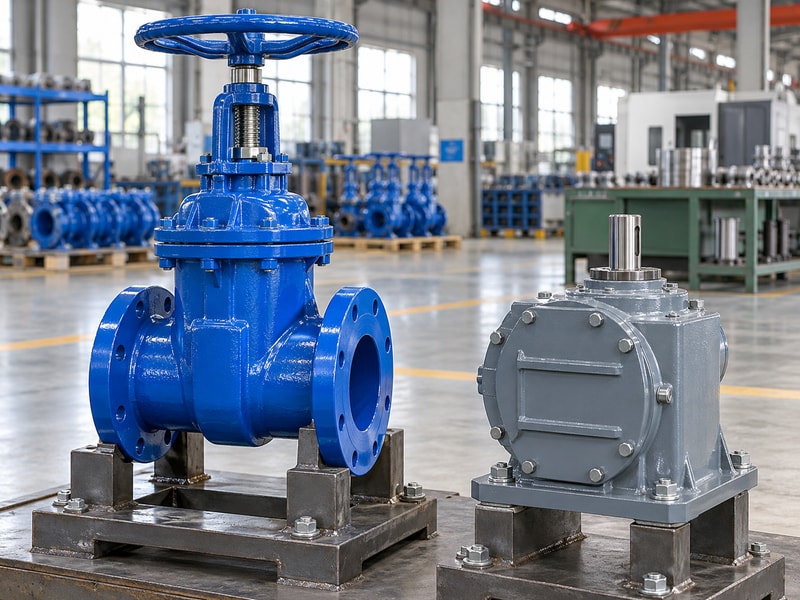
A multi-turn actuator gearbox supplies repeated rotation and may include a stem-driving or thrust-carrying arrangement for an appropriate valve. That function differs from a limited-angle butterfly valve drive. Identify the valve mechanism and all required loads before comparing multi-turn and part-turn assemblies that happen to use similar handwheels.
Which additional loads may matter?
Where a stem nut converts rotation into axial motion, the drive arrangement must suit the stem geometry and the required thrust support. Other assemblies may transmit torque without taking the same thrust load. Ask the supplier to identify the output function on a drawing, including the components that support the stem and the connection to the valve. Do not infer thrust capacity from a torque rating or assume a part-turn gearbox can replace a multi-turn mechanism.
- Identify whether thrust support is required.
- Confirm the stem-driving arrangement and geometry.
- Keep torque and thrust ratings separately identified.
Key takeaway: Match the gearbox to the valve’s actual mechanism and supported loads.
| Check | What to confirm |
|---|---|
| Part-turn function | Delivers limited-angle output torque. |
| Multi-turn function | Delivers repeated rotation and any specified stem-drive duty. |
4. How do manual and motor inputs compare?
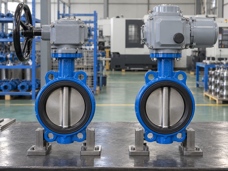
Manual and motor inputs to an actuator gearbox need different checks for input speed, duty and stopping behavior. A manual-only rating does not automatically cover powered operation. Confirm which input arrangements the selected gearbox permits and the restrictions that apply to each, including any required primary reduction or adapter.
How does the input review change?
For manual operation, check wheel or wrench effort, access and turns per stroke. For a motor-driven arrangement, check maximum input torque, input speed, duty and the control method used to stop travel. A powered drive may continue applying torque after a person would have noticed an abnormal load. Keep the valve and coupling limits visible in the review, then confirm that the chosen actuator settings do not exceed the weakest approved load limit in the assembly.
- Confirm each permitted input source.
- Check speed, torque and duty for powered operation.
- Review wheel effort and stroke turns for manual use.
Key takeaway: Approve manual and powered operating conditions separately for the same complete package.
| Check | What to confirm |
|---|---|
| Manual input review | Effort, access, connection and travel time. |
| Motor input review | Speed, duty, torque limiting and controls. |
5. When does a declutchable override fit?
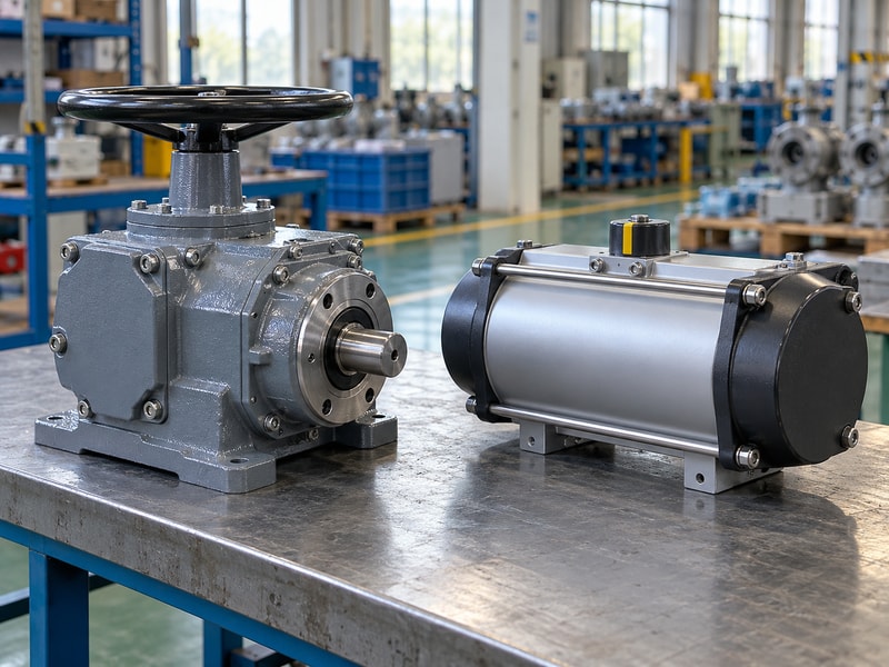
A declutchable actuator gearbox can provide a manual operating path when the design includes a suitable engagement and isolation arrangement. It must be selected for the actual valve and powered drive. An ordinary gearbox placed beside a pneumatic actuator does not establish a compatible override or a safe method of changing operating modes.
What should the changeover procedure prove?
Identify how the manual mechanism engages, how the powered drive is isolated or disengaged and what the operator must check before turning the handwheel. Review whether an inactive input can move and how the assembly returns to normal service. Follow the instructions for the exact mechanism instead of forcing an engagement control while the assembly is loaded or moving. Acceptance should include the agreed changeover sequence, manual travel and restoration of position indication and normal operation.
- Specify engagement and isolation behavior.
- Review movement of inactive inputs.
- Test changeover and restoration using the approved procedure.
Key takeaway: Buy the override as an approved functional assembly with an explicit changeover sequence.
| Check | What to confirm |
|---|---|
| Manual mode | Approved engagement and load transfer. |
| Normal mode | Defined disengagement and restored powered operation. |
6. How should ratio and input limits be checked?
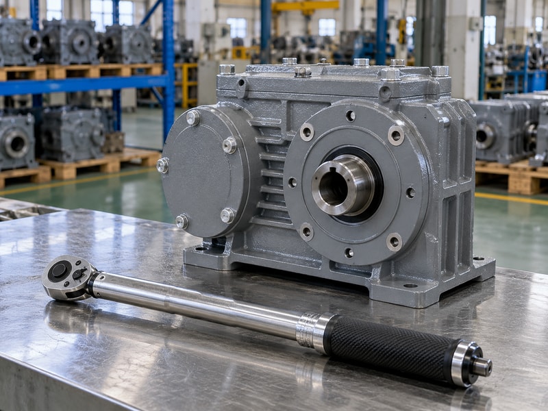
An actuator gearbox ratio must provide the required output while respecting the gearbox’s input torque, speed and duty limits. Efficiency affects the useful torque multiplication. Include every supplied reduction stage and compare the result with the valve’s required torque and the allowable loads of the shaft, coupling and mounting structure.
How do you keep a sizing sheet readable?
List the required valve torque and its service conditions at one side of the calculation, then show the proposed input, total ratio and applicable efficiency. State each sizing allowance instead of burying several margins in different catalogue selections. Add the resulting stroke turns or operating time. A proposal that delivers sufficient torque can still be unsuitable if it takes too long to move, exceeds an input limit or imposes more torque than the valve shaft permits.
- Show required and available torque on the same basis.
- Record total ratio and efficiency assumptions.
- Check travel time and all assembly load limits.
Key takeaway: Accept a calculation that addresses torque, speed and limiting components together.
| Check | What to confirm |
|---|---|
| Sizing inputs | Duty torque, input condition and agreed allowance. |
| Sizing outputs | Usable torque, stroke time and component-limit checks. |
7. Which couplings and flanges must match?
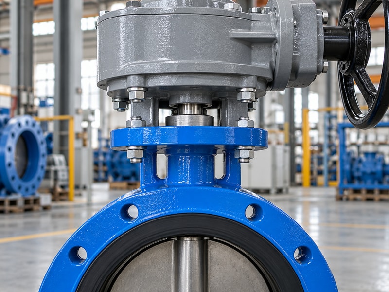
An actuator gearbox coupling and flange must match the valve and the input drive on their respective sides. A package can have a suitable valve-side output but an unsuitable motor-side mounting connection. Review both interfaces with their shaft forms, registers, engagement lengths and fasteners clearly identified.
Which connection is missing from many enquiries?
A request may include the valve topworks drawing but omit the connection to an existing electric multi-turn actuator or manual input extension. Ask for both mating drawings and check which adapter parts the supplier includes. Confirm alignment, axial clearance and load support across the assembled stack. Record any custom coupling or bracket as a controlled component, since future maintenance will need its dimensions and revision rather than only the gearbox’s standard catalogue number.
- Review input-side and valve-side interfaces.
- Identify all adapters and couplings in the scope.
- Control custom-part drawings and revisions.
Key takeaway: Approve both ends of the gearbox and every loaded connection between them.
| Check | What to confirm |
|---|---|
| Input interface | Drive mounting, shaft form and permitted loads. |
| Output interface | Valve topworks, coupling and reaction support. |
8. How do you choose environmental protection?
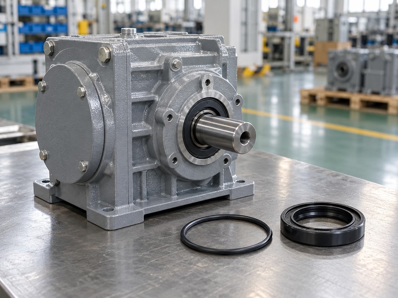
Environmental protection for an actuator gearbox should cover ambient temperature, moisture, corrosion and the installed access arrangement. The valve’s fluid rating does not establish the gearbox enclosure’s exposure capability. Define buried, submerged, washdown or outdoor conditions explicitly, and ask which configuration and maintenance requirements support the proposed protection.
What should be included beyond the housing material?
Review shaft seals, cover joints, lubricant, coating and exposed fasteners for the stated environment. Water can enter through an inappropriate input connection even when the main cover is sealed. An extension arrangement also needs its own protection and support details. Ask how the package will be stored before installation and inspected in service, especially where access is difficult, so the enclosure selection includes the conditions it will encounter before and after commissioning.
- State ambient and exposure conditions at the gearbox.
- Include input connections and extensions in the review.
- Confirm storage and maintenance requirements.
Key takeaway: Specify the full exposure and operating arrangement rather than a general weatherproof description.
| Check | What to confirm |
|---|---|
| Enclosure components | Housing joints, shaft seals and lubricant. |
| External components | Coating, fasteners, connections and extensions. |
9. What tests prove actuator gearbox compatibility?
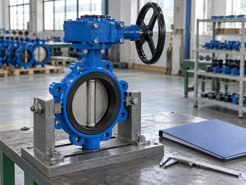
Actuator gearbox compatibility should be demonstrated on the complete valve-and-drive assembly using an agreed test scope. Fit and free movement are preliminary checks. The acceptance plan should also identify travel, indication, input limits, manual changeover and any required loaded operation, with test conditions recorded for each claimed function.
Which results should remain separate?
Record dimensional inspection and the identity of the supplied mounting parts, then verify physical travel and feedback. Test manual engagement and restoration where an override is included. If the package must operate against a specified valve load, identify how that requirement will be demonstrated in the workshop or at site. Keep valve leakage and pressure tests separate from gearbox function, since successful movement does not establish isolation performance or the process rating of the assembly.
- Check the supplied interfaces and revisions.
- Test each specified operating mode.
- Record conditions behind loaded performance claims.
Key takeaway: Accept compatibility through identified functions and test conditions, not a general statement that the parts fit.
| Check | What to confirm |
|---|---|
| Mechanical acceptance | Fit, travel, indication and operating modes. |
| Valve acceptance | Separate pressure and leakage requirements. |
10. What must an actuator gearbox order identify?
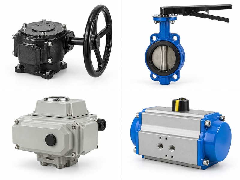
An actuator gearbox order should identify the exact input and output functions, load conditions, interfaces and supplied manual provisions. RUITO can review the requested valve drive arrangement against the available duty information. Keep a separate override, a motor-driven reduction and a manual handwheel package distinct in the quotation scope.
What makes the order repeatable?
Include the approved assembly drawing, supplied parts list, ratio, input limits, operating instructions and acceptance documents. Identify custom adapters and any restrictions on changing operating modes. For future orders, require review of changes to the gear arrangement, coupling, mounting height or control behavior. The equipment owner then has a defined configuration to maintain, while procurement can compare repeat supply against a technical record instead of an incomplete description from the original purchase order.
- Approve a complete configuration and supplied scope.
- Retain operating limits and changeover instructions.
- Review changes before repeat or replacement supply.
Key takeaway: Order the same defined assembly that was reviewed and tested.
| Check | What to confirm |
|---|---|
| Order identity | Configuration, interfaces and supplied accessories. |
| Service identity | Revisions, operating instructions and test records. |
Send the valve topworks drawing, normal drive details and manual-operation requirement when you contact us. RUITO can review the requested package and clarify the interfaces and approval information needed.
Frequently asked questions
Q1. Can I use any manual gearbox as an override?
No. The engagement, isolation, loads and interfaces must suit the powered valve package.
Q2. Does an actuator gearbox always increase torque?
Its function may include reduction or direction change. Check the ratio, efficiency and rated capacities of the actual arrangement.
Q3. Can a part-turn gearbox drive a rising-stem valve?
Do not assume it can. Identify the required rotation, stem-driving function and thrust support before selection.
Q4. What should I check on the motor side?
Check its mounting interface, shaft connection, input speed, torque and duty against the gearbox limits.
Q5. How do I verify a manual changeover arrangement?
Follow the approved procedure and test engagement, manual travel, indication and restoration to normal operation.