
Choose a valve operator by matching the valve’s motion and torque with available power, operating duty and required failure behavior. A manual gearbox, pneumatic actuator and electric actuator solve different operating problems. Define the duty and access conditions before comparing prices, especially when a valve must operate remotely or after power loss.
Images are AI-generated illustrations of generic equipment configurations.
1. Which valve operator types can you choose?
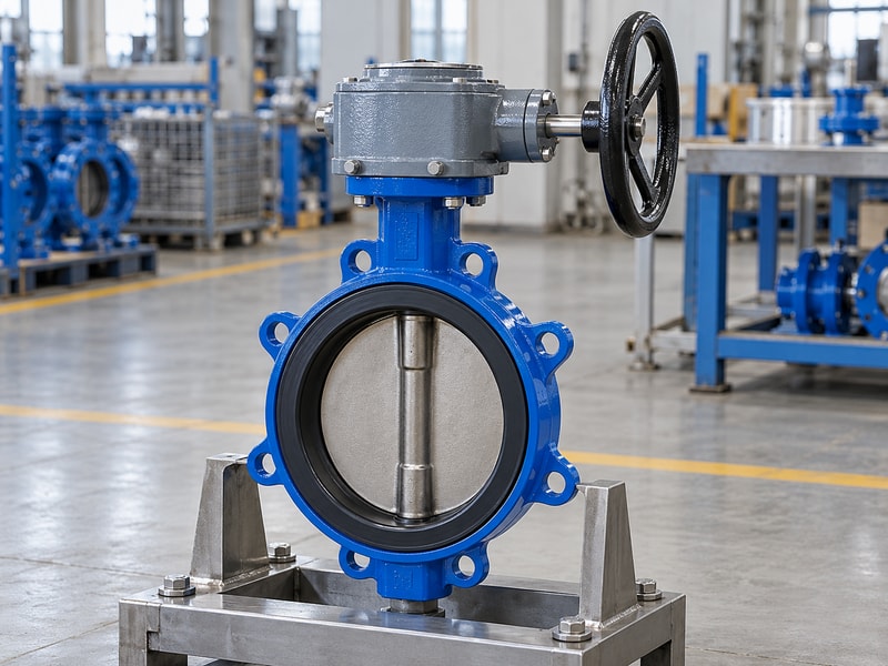
A valve operator can be a manual mechanism or a powered actuator that moves the valve’s closure member. The required output may be part-turn rotation, repeated rotation or linear travel. For butterfly valves, compare the proposed operator against the disc’s operating torque and the permitted travel, with the actual service conditions identified.
Which choices should be made together?
Begin with the valve mechanism, then consider how often it moves, who can reach it and which energy sources are available. A remote valve may need powered operation even when its torque is modest. An accessible isolation valve used infrequently may remain practical with manual operation. Keep process isolation requirements separate from the drive selection: changing the operator does not improve the valve’s pressure rating or make an unsuitable seat material compatible with the fluid.
- Identify the required output motion and travel.
- State frequency, accessibility and remote-control needs.
- Keep the valve’s process rating in the review.
Key takeaway: Choose the operating arrangement around a defined valve duty and the way the plant will use it.
| Check | What to confirm |
|---|---|
| Valve requirement | Motion, torque and process compatibility. |
| Operator requirement | Power, access, controls and operating frequency. |
2. When does a manual lever fit?
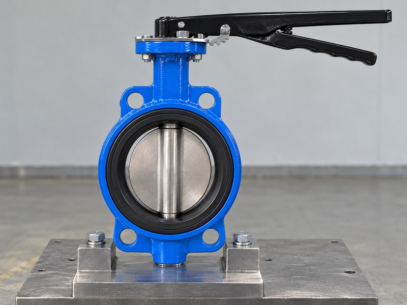
A manual-lever valve operator fits an application where the required effort and lever sweep are acceptable and someone can reach the valve. It offers direct operation with few drive components. Check actual valve torque and access rather than assuming that every small valve will be comfortable to move under its specified duty.
What should you inspect around the handle?
Check the full sweep, nearby pipework, guards and the operator’s standing position. A lever needs room to move and a suitable way to retain or identify its position where the application requires it. If extra force seems necessary, investigate the valve condition rather than fitting a longer improvised handle. For repeat equipment, verify the handle arrangement on the assembled sample so a nominally identical valve does not arrive with a different sweep or locking position.
- Check effort at the specified operating condition.
- Show the complete lever sweep on the layout.
- Specify position retention and identification needs.
Key takeaway: Use a lever where both the operating load and the physical access support manual operation.
| Check | What to confirm |
|---|---|
| Benefit | Direct operation with a short mechanical path. |
| Constraint | Required effort and handle sweep need checking. |
3. When should you use a geared handwheel?
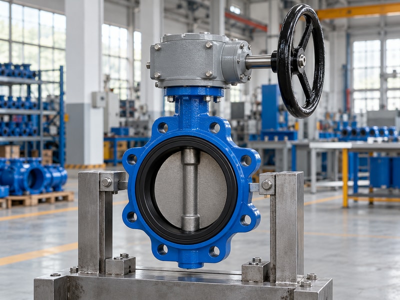
A geared-handwheel valve operator fits when manual operation remains appropriate but a direct lever would require excessive effort or an impractical sweep. The reduction increases input turns for the required valve travel. Confirm handwheel clearance, rim effort and complete-stroke time together before selecting the ratio and wheel diameter.
What changes for the person operating the valve?
A wheel can make the input force more manageable, but the operator must complete more turns and may need access from a particular side. A valve installed above normal reach may require an approved chainwheel or extension arrangement. Those options add their own support, guarding and maintenance requirements. Ask how the final installation will be operated and inspected, including any requirement to lock the valve in position or report its status to the control system.
- Compare rim effort with turns per stroke.
- Confirm reach and handwheel clearance.
- Review extensions or chainwheels as complete arrangements.
Key takeaway: Accept the geared handwheel only after checking how a person will use it at the installed location.
| Check | What to confirm |
|---|---|
| Effort | Reduction and wheel radius affect rim force. |
| Access | Wheel position, reach and stroke turns affect usability. |
4. When does pneumatic operation fit?
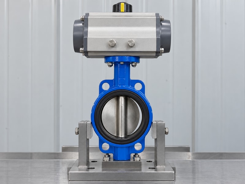
A pneumatic valve operator fits where the required air supply, control arrangement and operating duty can be supported. Rotary pneumatic designs can drive suitable butterfly valves through their required travel. Size the actuator using the minimum available air pressure and the valve’s torque requirements, including the appropriate air and spring strokes when applicable.
Which air-supply details belong in the enquiry?
State the minimum and maximum supply pressures at the actuator, air quality, tubing arrangement and any required stroke time. Identify double-acting or spring-return operation and the intended failure position. A spring-return arrangement needs adequate torque throughout both directions of travel; a single peak output figure does not establish that. Include solenoid valves, positioners and feedback devices in the control review so the assembled package performs the requested sequence rather than only passing a bare-actuator bench check.
- Use minimum supply pressure for sizing.
- Compare the required torque across the full stroke.
- Define air loss, signal loss and control behavior.
Key takeaway: Specify pneumatic power and fail behavior at the complete assembly level.
| Check | What to confirm |
|---|---|
| Power conditions | Supply pressure, air quality and flow capacity. |
| Control conditions | Direction, speed, feedback and failure response. |
5. When does an electric valve operator fit?
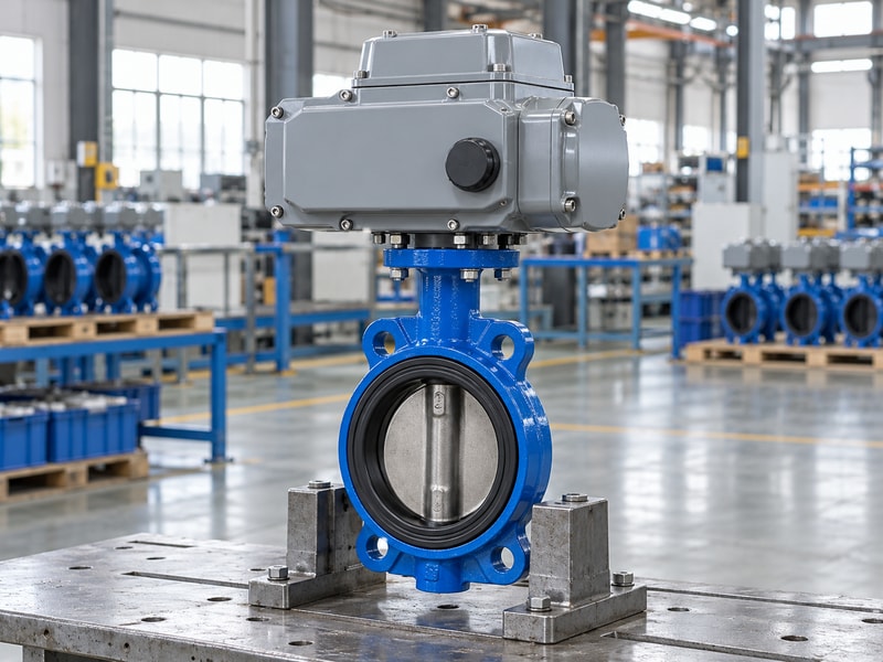
An electric valve operator fits when suitable electrical power and the required control functions are available at the installation. Its motor, gear train and controls must suit the valve torque, stroke time and duty. Identify the exact supply and enclosure requirements rather than relying on a general description such as electric actuation.
What should electrical and mechanical teams agree?
Confirm supply voltage and frequency where relevant, control signals, feedback, cable entry and the permitted operating sequence. Review starts, recovery periods and positioning duty against the actuator rating. Travel and torque settings must also agree with the valve seating instructions and the gearbox input limit where a separate gearbox is supplied. Arrange any manual operation so maintenance can follow a defined isolation and changeover procedure rather than attempting to drive against an active motor.
- State supply and control requirements explicitly.
- Check duty and loaded stroke time.
- Coordinate limits, torque settings and manual operation.
Key takeaway: Approve the motor, gearing and controls as one operating package with the valve.
| Check | What to confirm |
|---|---|
| Electrical review | Supply, controls, feedback and enclosure. |
| Mechanical review | Torque, travel, duty and mounting limits. |
6. When should a hydraulic valve operator be considered?
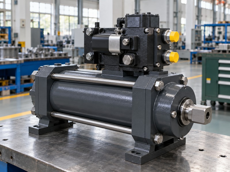
A hydraulic valve operator may be considered when the project’s load, response or existing power system supports a hydraulic arrangement. It needs a defined pressure source, control circuit and suitable connection to the valve. Its suitability should be evaluated for the specific package rather than inferred from a high advertised output torque.
Which additional systems must be included?
Clarify whether a hydraulic power unit already exists and what pressure, flow, fluid and environmental conditions it can provide. Include hoses, accumulators, control valves and any manual provision in the package review where they are required. Discuss fluid containment and maintenance access with the system designer. If a supplier’s standard valve offer covers manual, electric or pneumatic drives, identify a hydraulic request as a separate technical scope and obtain confirmation before treating it as available supply.
- Define the complete hydraulic supply conditions.
- Identify controls and auxiliary equipment.
- Confirm that the requested scope is offered and reviewed.
Key takeaway: Treat hydraulic operation as a system proposal with a confirmed supply scope.
| Check | What to confirm |
|---|---|
| Hydraulic input | Pressure, flow, fluid and available infrastructure. |
| Package scope | Drive, controls, connections and auxiliary equipment. |
7. What should happen after power loss?
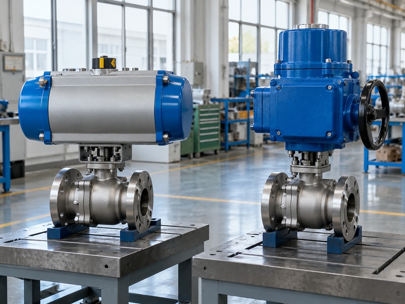
The valve operator failure response must follow the plant’s required behavior after loss of power, air or control signal. Holding the last position, moving closed and moving open are different functions. Specify the initiating event and required response time, then confirm that the proposed energy and control arrangement can deliver that movement.
How do you prevent an ambiguous fail-action statement?
Describe each relevant loss separately, including electrical power to a solenoid or controller even where the main drive uses compressed air. A spring, stored hydraulic energy or an approved electrical backup arrangement may supply the movement, depending on the design. A handwheel or manual override only provides a way for a person to act. Test the specified loss conditions during acceptance and record the resulting valve movement and indication against the agreed procedure.
- State the loss event and required final position.
- Identify the energy available for the response.
- Test each specified loss condition separately.
Key takeaway: Replace a vague fail-safe description with a defined event, movement and acceptance test.
| Check | What to confirm |
|---|---|
| Automatic response | Needs a suitable energy and control arrangement. |
| Manual response | Needs access, an operator and an approved procedure. |
8. Which feedback and controls do you need?
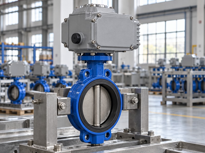
Valve operator feedback should report the states needed for the plant’s operating sequence, such as confirmed end positions, continuous position or a detected fault. Decide how those signals enter the control system. A command sent to the operator is different from a measured indication that the valve reached the intended position.
Which signals are useful for the application?
An isolation valve may need open and closed contacts, while a positioning application may require continuous feedback and a defined accuracy. Identify sensor location, signal type and the response to missing or inconsistent signals. Check that the indication reflects the assembled coupling orientation, especially after a retrofit or repair. Position information supports operation, but seat leakage remains a separate valve performance check and should not be inferred from an illuminated closed signal.
- Define end-position or continuous feedback.
- State signal types and fault handling.
- Verify indication after assembly or maintenance.
Key takeaway: Specify feedback by the plant decision it supports and the point it measures.
| Check | What to confirm |
|---|---|
| Control command | Requests a movement or position. |
| Position feedback | Reports a measured state at its sensing point. |
9. How do you compare operating costs?
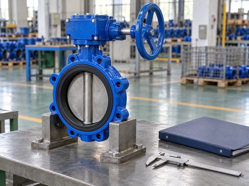
Valve operator cost should be compared across purchase, installation, energy, inspection and service requirements for the same duty. A low actuator price can omit controls or mounting parts that another quotation includes. Compare complete supplied scope and the work needed at site before deciding which operating arrangement costs less.
Which costs differ between the options?
Manual operation requires access and staff time, while powered arrangements add their own supply, controls and maintenance needs. Frequent operation may make those differences more consequential than the initial price. Ask each supplier to identify adapters, switches, solenoids, cables or tubing included in the offer. Keep any estimated running or maintenance costs tied to stated assumptions, since operating frequency and local infrastructure can change the comparison considerably between two otherwise similar valve positions.
- Compare the same operating duty and supplied scope.
- List installation and control-system work.
- State assumptions behind lifetime-cost estimates.
Key takeaway: Compare installed operating packages, with omissions and assumptions visible.
| Check | What to confirm |
|---|---|
| Initial scope | Valve, drive, mounting and supplied controls. |
| Operating scope | Access, energy, inspection and service work. |
10. What should a valve operator specification include?
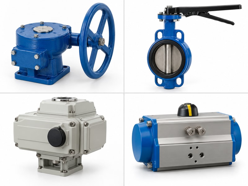
A valve operator specification should connect the process duty with motion, torque, power, controls and acceptance requirements. RUITO can review manual, electric or pneumatic arrangements for the requested valve package. Identify other drive requests separately so the proposed supply scope and technical review remain explicit.
What should purchasing receive from engineering?
Provide the valve data sheet, torque requirements, mounting drawing and installation environment, then add operating frequency, stroke time, feedback and failure behavior. Ask for the selected configuration and its limitations in the quotation. Approve the assembly drawing and test plan before manufacture, and retain the resulting documents for repeat orders and service. This makes a later replacement a controlled equipment decision instead of a new selection based only on the old actuator’s appearance.
- Send valve duty and operating requirements together.
- Approve interfaces, controls and test conditions.
- Retain the selected configuration and revisions.
Key takeaway: Release a defined valve-and-operator package with agreed performance and documentation.
| Check | What to confirm |
|---|---|
| Technical inputs | Duty, motion, torque, power and controls. |
| Acceptance outputs | Approved configuration, tests and operating documents. |
Send your valve data sheet and operating requirements when you contact us. RUITO can review the manual, electric or pneumatic arrangement and the interfaces needed for the requested package.
Frequently asked questions
Q1. Can I change a manual valve to powered operation?
Often a conversion is possible, but the torque, interfaces, support and controls require review for the actual valve.
Q2. Does every electric actuator close after power loss?
No. The required failure response needs a suitable energy and control arrangement.
Q3. Should I size a pneumatic actuator at normal air pressure?
Use the minimum available supply pressure and check the required torque throughout the relevant strokes.
Q4. Do I need continuous position feedback for isolation duty?
It depends on the plant sequence. Define the information the control system needs before selecting feedback.
Q5. What makes two quotations comparable?
The same valve duty, operator function, supplied controls, mounting scope, tests and documentation.