
Identify a gear operator by its complete drive arrangement, ratings and interfaces before ordering parts or a replacement. A similar handwheel and housing can hide different worms, output sleeves and travel stops. Trace the load path and record the equipment identity so a repair request reaches the correct component set.
Images are AI-generated illustrations of generic equipment configurations.
1. What is inside a gear operator?
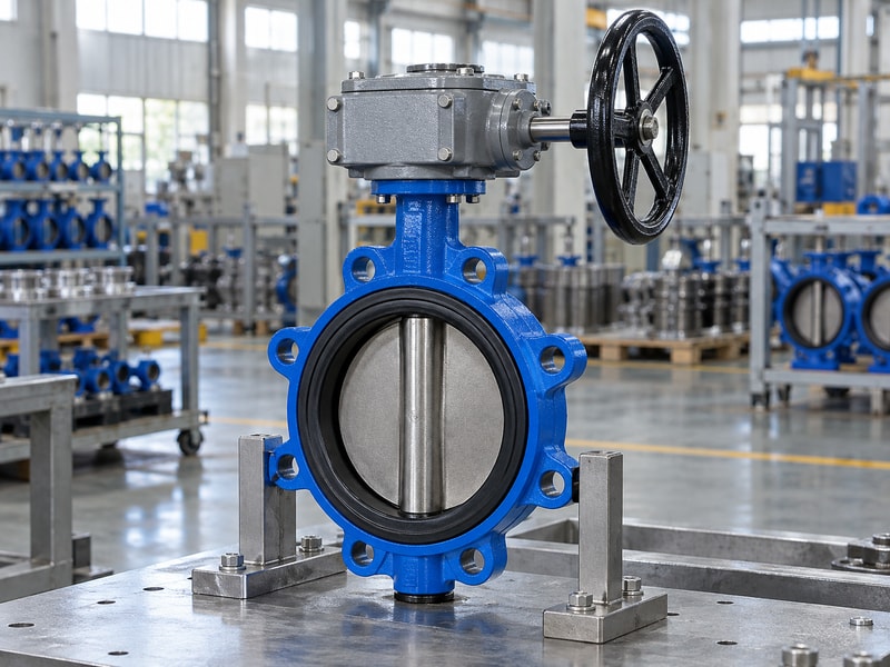
A gear operator contains the components that turn an input effort into the motion required at a valve shaft. A manual worm arrangement commonly includes an input shaft, worm, wheel or sector, bearings, output sleeve, seals, housing and travel-setting parts. The exact parts and their serviceability depend on the manufacturer’s design.
How should you read the parts arrangement?
Follow the input through the gear train and into the output connection, then trace reaction loads back through the housing and mounting flange. This separates torque-carrying parts from covers and indicators, which can look prominent in a photograph without carrying the drive load. Use the approved parts drawing to identify each component. A photograph helps establish the configuration, but it cannot replace hidden dimensions or determine whether a worn internal part is supplied separately.
- Record the complete equipment identity.
- Use the correct revision of the parts drawing.
- Distinguish load-carrying and indication components.
Key takeaway: Start a parts discussion with the assembly identity and drawing rather than a loose component name.
| Check | What to confirm |
|---|---|
| Drive components | Transmit input motion and output torque. |
| Supporting components | Maintain alignment, sealing and indication. |
2. How does the input assembly work?
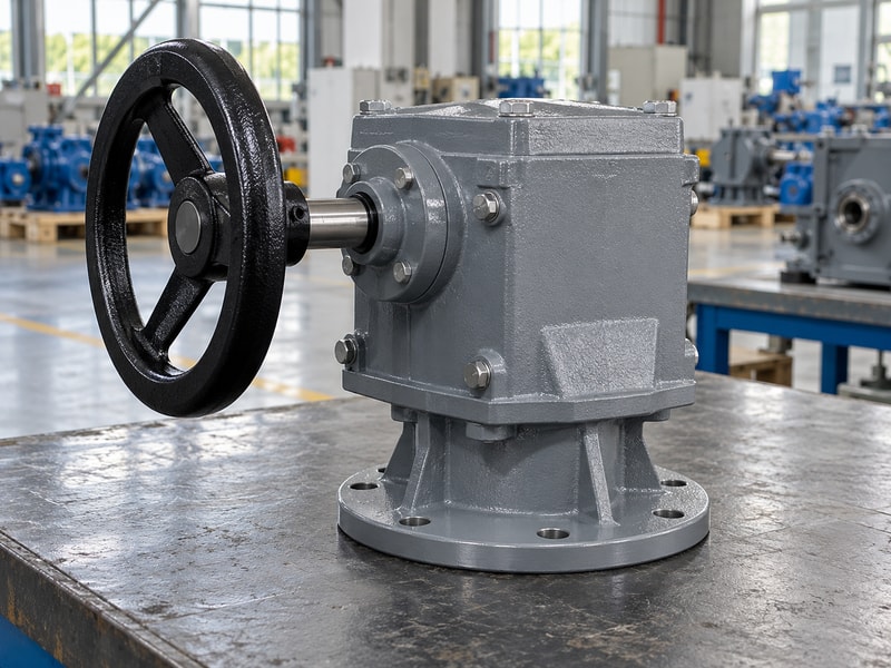
The gear operator input assembly receives handwheel or other approved driving torque and passes it into the gear train. The shaft, wheel connection, bearings and retention arrangement must remain compatible. A larger handwheel can increase applied torque, so replacing one with a larger diameter needs a load and clearance check.
Which handwheel details affect a replacement?
Record wheel diameter, hub bore, key or other drive feature, retention method and shaft projection. Check whether the input is intended for a handwheel, chainwheel or wrench connection. A wheel that fits the shaft may still interfere with adjacent pipework or allow an operator to exceed the permitted input torque. If an extension is required, ask for the approved support and connection arrangement instead of adding a long unsupported shaft.
- Measure the wheel and hub connection.
- Confirm the intended input method.
- Check clearance and maximum permitted input.
Key takeaway: Replace the input assembly with a configuration that preserves both fit and operating limits.
| Check | What to confirm |
|---|---|
| Wheel fit | Diameter, hub, key and retention. |
| Input limit | Permitted torque and approved drive method. |
3. What do the worm and wheel transmit?
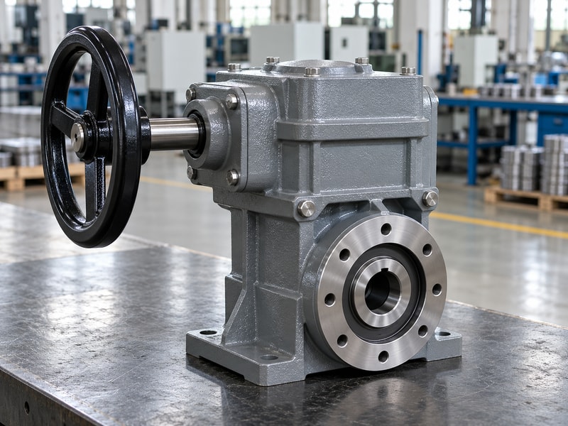
The worm and wheel in a gear operator transmit torque through a specific tooth geometry and contact arrangement. Their ratio does not identify every dimension needed for interchangeability. A replacement wheel must suit its mating worm, shaft support and housing, with the intended material pairing and clearances.
Why is outside diameter an incomplete description?
Two wheels can share an outside diameter while differing in tooth count, pitch, face geometry or bore. A sector can also cover a different travel range even when its visible tooth section looks similar. Request replacement parts against the original equipment identification and the supplier’s drawing. If the manufacturer calls for a matched set or complete gearbox replacement, do not assume that a single locally machined part will preserve the original load capacity.
- Identify the mating worm and wheel or sector.
- Confirm the approved parts supply scope.
- Review any proposed material or geometry change.
Key takeaway: Treat the gear pair as a designed contact arrangement whose parts require confirmed compatibility.
| Check | What to confirm |
|---|---|
| Visible similarity | Does not establish tooth or bore compatibility. |
| Approved replacement | Matches the specified gear set and support arrangement. |
4. Why do bearings and seals affect operation?
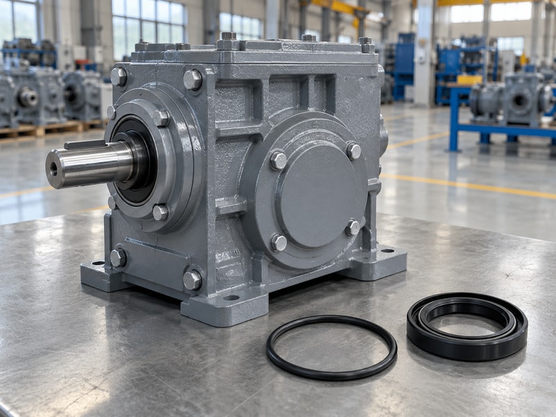
Bearings and seals in a gear operator affect shaft alignment, friction and protection of the internal mechanism. A damaged seal can allow contamination even when the housing looks sound. Bearing damage or incorrect support can also change tooth contact, so inspection should connect the symptom with the load path.
What should a service-parts enquiry record?
Identify the shaft location, bearing or seal designation where available, and the conditions under which leakage or roughness appeared. Include ambient exposure and lubricant information because a compatible material and sealing arrangement may depend on those conditions. Before dismantling, isolate the equipment and follow its maintenance procedure, including support of any loaded components. Keep removed parts identified by position so the supplier can distinguish similar items used at different points in the housing.
- Record the exact component position.
- Describe leakage, roughness and exposure conditions.
- Follow the approved isolation and dismantling procedure.
Key takeaway: Describe where a bearing or seal works and what changed, not only what the removed part looks like.
| Check | What to confirm |
|---|---|
| Bearing function | Supports shafts and the specified gear loads. |
| Seal function | Retains lubricant and limits contamination. |
5. How do travel stops and indicators work?
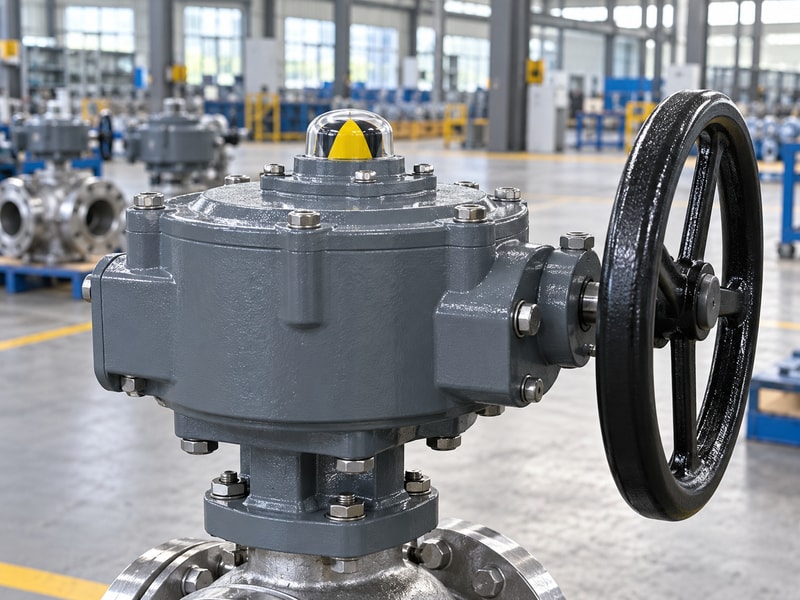
Travel stops in a gear operator limit permitted motion, while indicators display an intended relationship with valve position. Their settings must follow the valve’s seating instructions. Neither a stop contact nor a closed indication proves acceptable leakage, and extra force against a stop is not a substitute for correct adjustment.
How do you verify the indication?
Compare the indicator with the physical disc or other closure member during a controlled check before the assembly enters service. Confirm that the coupling has the correct angular orientation and that the approved stops allow the required travel. If an indicator slips or the coupling changes position, investigate the cause before relabeling the display. Retain the final settings with the equipment record so later maintenance does not rely on an unverified pointer position.
- Verify physical travel before accepting the display.
- Set stops using the valve instructions.
- Record the final settings and orientation.
Key takeaway: Check travel, indication and valve leakage as separate functions with separate acceptance evidence.
| Check | What to confirm |
|---|---|
| Travel stop | Limits permitted mechanical movement. |
| Position indicator | Displays position at a defined connection point. |
6. Which gear operator type fits the valve?
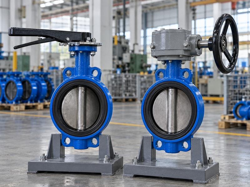
The appropriate gear operator type depends on the valve’s required output motion, input arrangement and load. A part-turn worm drive may suit a butterfly valve, while a multi-turn valve needs a different output function. Compare the complete mechanism rather than assuming every manual handwheel operator performs the same job.
Which questions separate the types?
Ask whether the output must rotate less than a full turn, rotate repeatedly or develop thrust through a stem-nut arrangement. Then identify the input direction, access space and whether a powered drive or manual override is included. These choices affect gears, bearings and mounting loads. For a replacement, preserve the approved function unless engineering has reviewed a change; a different arrangement can require new controls, support or operating instructions even if the valve itself stays in place.
- Specify the required output motion.
- Identify torque and any required thrust capacity.
- Include input access and operating modes.
Key takeaway: Select the operator type from the valve mechanism and installation duty.
| Check | What to confirm |
|---|---|
| Part-turn output | Limited-angle movement for suitable rotary valves. |
| Multi-turn output | Repeated rotation and any specified stem-drive function. |
7. How should you match torque capacity?
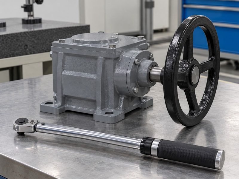
A gear operator must deliver the required valve torque while keeping input, output, shaft, coupling and mounting loads within their allowable limits. The most restrictive component controls the usable arrangement. A gearbox with a high catalogue output rating cannot protect a weaker valve stem from excessive applied torque.
What belongs in the load review?
Use the valve supplier’s torque requirements for the specified medium, temperature and maximum closing differential pressure. Identify breakaway, running and seating conditions where the design requires them, then check the supplied operator across the relevant travel. Apply the agreed sizing allowances transparently rather than adding arbitrary margins at several stages. Finally, check the wheel diameter or powered input settings so the assembled package respects the limiting component during actual operation.
- Use the valve’s duty-specific torque data.
- Compare all torque-carrying component limits.
- Record sizing allowances and input restrictions.
Key takeaway: Approve required torque and allowable assembly loads on the same calculation sheet.
| Check | What to confirm |
|---|---|
| Required load | Valve duty and agreed sizing allowance. |
| Allowable load | Input, output, shaft, coupling and mount limits. |
8. What belongs in a gear operator parts request?
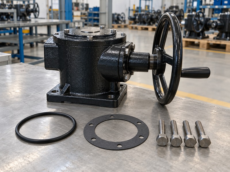
A gear operator replacement-parts request should identify the assembly, the failed or required component and its mating interfaces. Include equipment photographs, markings and the approved parts drawing where available. Measurements are useful, but they should support confirmed identification rather than serve as the only evidence of compatibility.
Which information saves a second enquiry?
Send the gearbox identity and ratio, valve identity, output shaft form, mounting pattern and the position of the requested part on the drawing. Describe the failure or reason for replacement, including whether the valve became difficult to operate before the gearbox symptom appeared. Ask the supplier to state whether the item is serviceable, sold as a matched set or supplied only within a larger assembly. This makes the quotation scope clear before procurement compares prices.
- Attach identification and clear configuration photographs.
- Mark the requested part on the parts drawing.
- Ask for the exact supply and compatibility scope.
Key takeaway: Request a defined part or assembly with confirmed mating components and documented limits.
| Check | What to confirm |
|---|---|
| Identification | Equipment markings, drawing and component position. |
| Compatibility | Mating parts, dimensions and approved supply scope. |
9. How should a fault be investigated?
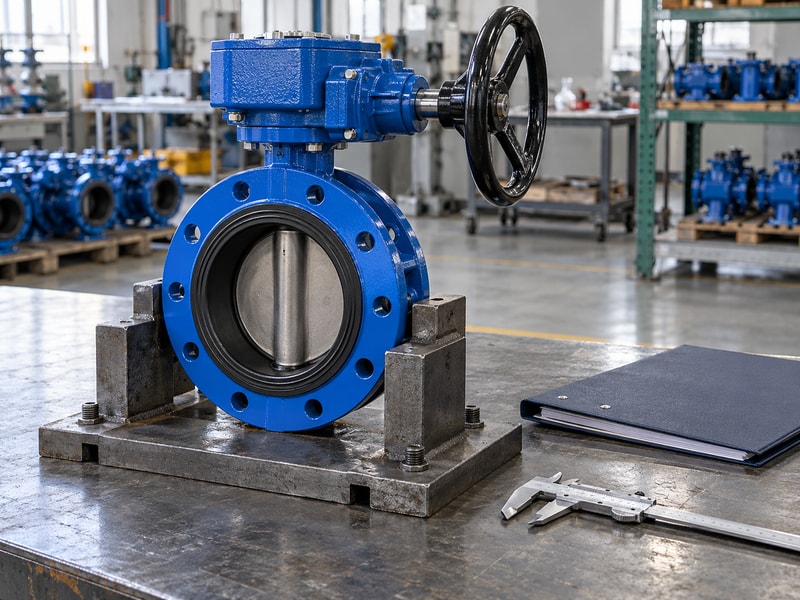
A gear operator fault should be investigated across the valve, mounting and drive before a damaged part is replaced. Rising effort can originate in a valve obstruction or misalignment as well as the gearbox. Replacing the visible failed component without checking its cause can expose the new component to the same load.
How do you organize the investigation?
Record when the symptom occurs, the direction of travel, process conditions and any recent maintenance or adjustment. Compare these observations with the original operating baseline, then isolate the equipment before inspection. Check mounting condition, coupling alignment, indication and external leakage before following the manufacturer’s internal inspection procedure. Preserve evidence of damage and avoid guessing a new torque limit from the amount of force that a surviving component appears to tolerate.
- Record the symptom and operating conditions.
- Inspect the complete load path after isolation.
- Resolve the cause before returning the assembly to duty.
Key takeaway: Link the repair to a documented cause and a controlled return-to-service check.
| Check | What to confirm |
|---|---|
| Symptom record | Direction, travel position and process conditions. |
| Cause review | Valve, mounting, coupling and internal mechanism. |
10. What records support a reliable order?
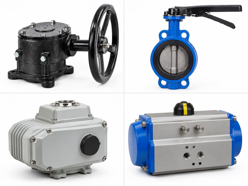
A gear operator order should preserve the identity, ratings and interfaces that engineering approved. RUITO can review the valve duty and mounting details for a supplied valve package. Keep gearbox service parts and process-wetted valve parts clearly identified, since they solve different maintenance tasks and need different compatibility evidence.
What should the final record contain?
Retain the quotation scope, approved drawing, parts list, operating instructions and acceptance results together with the equipment identification. Record any permitted alternatives and their revisions. For repeat orders, require review before changes to the output bore, gear set, bracket or operating limit. Procurement can then request the same approved configuration, while maintenance has enough information to identify a replacement without relying on memory or an old photograph of the handwheel.
- Keep drawings and parts lists with the equipment ID.
- Record approved alternatives and changes.
- Retain functional checks after repair or replacement.
Key takeaway: Make the equipment record specific enough for the next person to order and verify the correct assembly.
| Check | What to confirm |
|---|---|
| Purchase record | Approved scope, drawings and operating limits. |
| Maintenance record | Parts used, findings and return-to-service checks. |
Send the equipment identity, valve duty and interface drawing when you contact us. RUITO can review the supplied valve arrangement and the information needed for a matching drive package.
Frequently asked questions
Q1. Can I identify a gear operator by its handwheel size?
No. Record the gearbox identity, ratings, ratio, output connection and mounting dimensions.
Q2. Can I replace only the damaged worm wheel?
Ask the manufacturer. The design may require a matched gear set or a complete assembly.
Q3. Does a closed indicator mean the valve is leak-tight?
No. Indication and seat leakage require separate checks.
Q4. Can a larger handwheel make operation easier?
It can reduce rim force for a given input torque, but it also changes clearance and the torque an operator can apply.
Q5. What should I do if the new gearbox also becomes hard to turn?
Stop and investigate the valve duty, alignment and complete load path before applying more force.