

Fix butterfly valve actuator orientation by aligning the drive, protecting controls, and keeping service points reachable within the approved mounting arrangement. A cramped skid can leave a cable entry against a wall or a coupling partly engaged. Check the assembly drawing and actuator manual before choosing a clock position or changing an installed mount.
1. What sets butterfly valve actuator orientation?
The approved valve and actuator assembly drawing sets butterfly valve actuator orientation, together with the actuator installation manual. Clock position describes where the housing sits around the stem axis, while stem attitude describes how that axis lies in space.
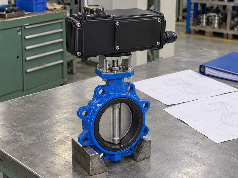
Which drawing controls the position?
Match the viewing direction before naming a clock position. A drawing should show whether you are looking toward the valve or outward from its mounting face. Without that reference, two installers can interpret the same position differently and place controls on opposite sides of a pipe.
- Confirm valve and actuator identification.
- Mark the viewing direction and mounting face.
- Record control and access locations.
A housing that fits one bolt pattern may still obstruct a cover or have an unsupported overhang. Check the full assembly envelope against nearby pipework, insulation, platforms, and removable equipment before release.
What should you record?
Key takeaway: A clock position needs a defined view and an approved assembly arrangement. Record both so procurement and installation use the same geometry.
| Item | Record |
|---|---|
| Reference view | Looking toward mounting face |
| Housing position | Approved clock setting |
| Clearance | Working and removal space |
Ask the supplier for a marked general arrangement drawing. Resolve any mismatch before the unit reaches the installation area.
2. Can butterfly valve actuator orientation be rotated?
A housing can be re-clocked only when its approved interface and instructions permit that change; butterfly valve actuator orientation is not universally adjustable. Bolt symmetry alone cannot confirm that the coupling, accessories, or internal travel arrangement will remain correct.
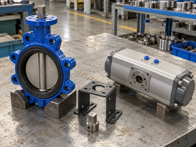
What changes with re-clocking?
Confirm the permitted rotation before removing fasteners. Some assemblies allow specified housing positions, while others need a different bracket or drive insert. A changed mount can also move an indicator away from its readable face or place an air port beneath a drainage path.
- Check permitted mounting positions.
- Confirm coupling indexing and insertion depth.
- Review accessory clearance at both end positions.
Isolate process pressure and actuator energy before dismantling an installed assembly. Follow the manufacturer's procedure for restraining the disc and releasing stored pneumatic or spring energy; do not loosen a pressurized mounting arrangement to gain clearance.
How should a change be approved?
Key takeaway: Re-clocking requires mechanical and accessory checks as one assembly. Written approval should identify the replacement parts and verification steps where needed.
| Change | Approval check |
|---|---|
| Housing rotation | Allowed mount positions |
| New bracket | Geometry and load capacity |
| New insert | Engagement and indexing |
Submit the proposed position with photographs or a layout drawing. Hold the change until its effect on travel and fail action is resolved.
3. How does butterfly valve actuator orientation affect coupling?
Correct butterfly valve actuator orientation preserves coaxial alignment and the specified coupling engagement between actuator output and valve stem. A coupling that bottoms out too early or grips only a short length can transfer unintended loads or lose drive.
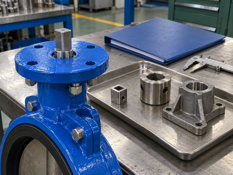
Which dimensions need checking?
Verify the coupling before changing the mount. Compare stem projection, output recess depth, insert dimensions, and bracket height with the approved drawing. A flange face that bolts down neatly can conceal an incorrect axial fit beneath it.
- Check square, key, or spline dimensions.
- Confirm full specified engagement.
- Keep required axial clearance and retention.
An ISO 5211 mounting interface helps define connection dimensions, but it does not guarantee torque capacity or compatibility. For flanged butterfly valve assemblies, include the actual stem and mounting geometry in the review rather than approving a drive by valve diameter alone.
What indicates acceptable engagement?
Key takeaway: Coupling fit must transmit the required torque without forcing axial or side loads into the stem. Verify dimensions before powered movement.
| Feature | Acceptance basis |
|---|---|
| Drive shape | Matching approved dimensions |
| Engagement | Specified insertion length |
| Axial fit | Required clearance and retention |
Record the checked dimensions on the assembly sheet. Stop assembly if the mount needs bolt force to pull mating faces together.
4. What supports butterfly valve actuator orientation?
The approved bracket and support arrangement carry the housing weight and operating reactions for butterfly valve actuator orientation. A side-mounted actuator creates an overhang that can load the mounting neck differently from a housing positioned above the stem.
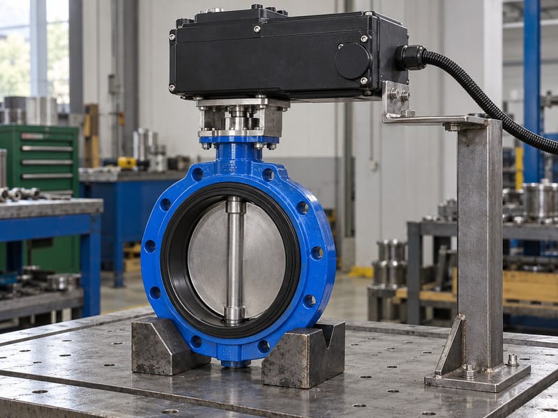
Which loads belong in the review?
Check the support path before accepting an overhang. The review should include actuator mass, centre of gravity, operating torque, vibration, and any attached manual override. Moving a housing sideways can change the bending load even when its torque output remains unchanged.
- Confirm bracket stiffness and fasteners.
- Check valve stem and neck load limits.
- Review movement at operating temperature.
Use only supports approved for the assembly. An improvised rigid support can restrain pipe movement and push misalignment into the drive; pneumatic tubing and electrical conduit should never carry housing weight.
What should the support drawing show?
Key takeaway: A support must carry its assigned load while preserving drive alignment. Pipe support and actuator support need coordinated movement allowances.
| Load | Review point |
|---|---|
| Housing weight | Bracket bending |
| Operating reaction | Mount fasteners |
| Pipe movement | Support restraint |
Ask engineering to mark the support attachment points. Inspect them after installation before energising the drive.
5. How does butterfly valve actuator orientation protect controls?
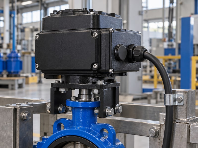
Suitable butterfly valve actuator orientation keeps covers, seals, cable entries, and local controls within their approved environmental conditions. Rotating an enclosure can move a vulnerable entry into falling water or make a cover impossible to remove.
What protects the enclosure?
Check cable entries in the installed position. Select glands and blanking plugs for the specified enclosure, cable size, and site environment. Route cables with supported bends and any drainage arrangement required by the actuator manual; a downward entry is useful only when that position is permitted.
- Keep covers accessible for inspection.
- Fit approved seals, glands, and plugs.
- Check condensation control where specified.
For chemical processing installations, external splash and cleaning chemicals need review alongside the valve's wetted materials. A compatible valve lining does not establish that the actuator enclosure, display window, or cable jacket tolerates those chemicals.
What belongs on the environment checklist?
Key takeaway: Enclosure protection depends on the complete installed arrangement. Accessory openings and cable routing must match the stated protection requirements.
| Exposure | Check |
|---|---|
| Rain or washdown | Entries and cover seals |
| Chemical splash | External material compatibility |
| Condensation | Approved control provisions |
Inspect the enclosure after cables are terminated. Confirm that service access remains available with insulation and guards fitted.
6. How does butterfly valve actuator orientation route air lines?
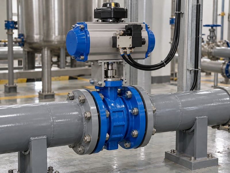
Good butterfly valve actuator orientation gives pneumatic ports and accessories enough space for supported tubing, exhaust discharge, and adjustment. A short tube route can still be unsuitable if it kinks during movement or obstructs the manual override.
What should the air layout include?
Trace each air connection before connecting the supply. Check port labels, solenoid orientation, regulator access, and the permitted position of a positioner. Exhaust fittings need protection against blockage and an appropriate discharge location, especially where surrounding equipment generates dust or splash.
- Identify supply and working ports.
- Support tubing without housing strain.
- Keep drains and adjustments reachable.
Minimum available air pressure is a sizing input, so confirm it at the actuator under the intended operating conditions. Air pressure inside the drive is separate from pressure in the process pipe; changing either condition can change whether the selected assembly completes its stroke.
How can you check the routing?
Key takeaway: Pneumatic routing must preserve supply, exhaust, and service access. Shortening a tube is useful only if its bend and connections remain sound.
| Connection | Installed check |
|---|---|
| Supply | Available pressure and isolation |
| Working lines | Correct ports and bends |
| Exhaust | Clear discharge route |
Mark the ports on the commissioning sheet. Check for damaged tubing before carrying out the approved functional procedure.
7. How does butterfly valve actuator orientation affect feedback?
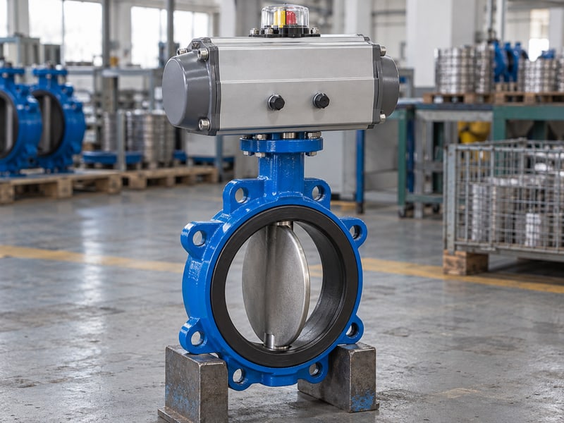
A change in butterfly valve actuator orientation requires confirmation that local indication and remote feedback still agree with actual disc travel. An indicator showing closed proves only its own setting until it has been checked against the valve position.
Which signals need comparison?
Prove disc position before setting the feedback. Use the approved reference marks or inspection method under isolated conditions. Check open and closed switches, intermediate position where supplied, and the command-to-motion relationship after any coupling or mounting change.
- Compare local indication with actual travel.
- Check both end-position signals.
- Confirm command labels and wiring records.
For a hypothetical cooling skid, rotating a limit-switch box may improve access while leaving its cam setting incorrect. A remote closed signal could then arrive before the disc reaches its approved seating position, so commissioning must check the mechanical position and signal together.
What confirms reliable indication?
Key takeaway: Feedback must represent verified valve travel. A working electrical contact cannot compensate for incorrect coupling indexing or endpoint settings.
| Observation | Compare with |
|---|---|
| Local pointer | Disc reference position |
| End switches | Approved endpoints |
| Control display | Recorded signal mapping |
Record agreement at both ends of travel. Investigate discrepancies before releasing the valve for automatic operation.
8. What fail action fits butterfly valve actuator orientation?
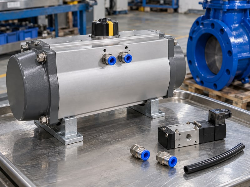
Fail action comes from the approved drive and control design, not housing clock position; butterfly valve actuator orientation must preserve that design. Loss of air, electrical power, or control signal can produce different outcomes and needs separate review.
Which failure condition must be specified?
Define the energy-loss condition before ordering the drive. A spring-return pneumatic actuator, a double-acting drive, and an electric actuator have different response arrangements. Accessory plumbing, reserve energy, and control logic can change the final position, so a fail-close label alone is incomplete.
- State the failed energy or signal source.
- Define required final disc position.
- Check the complete travel torque requirement.
In water and wastewater systems, rapid movement may affect surge conditions and neighbouring equipment. The project designer must approve response time and sequence; fitting a larger drive does not independently establish an acceptable shutdown response.
What should the fail-action record contain?
Key takeaway: Fail action requires a stated trigger, final position, and accepted movement sequence. Mounting changes must retain all three.
| Condition | Required record |
|---|---|
| Loss of supply | Intended final position |
| Loss of command | Control response |
| Recovery | Restart sequence |
Review the cause-and-effect schedule with controls engineering. Use its approved procedure for the failure-response check.
9. How is butterfly valve actuator orientation commissioned?
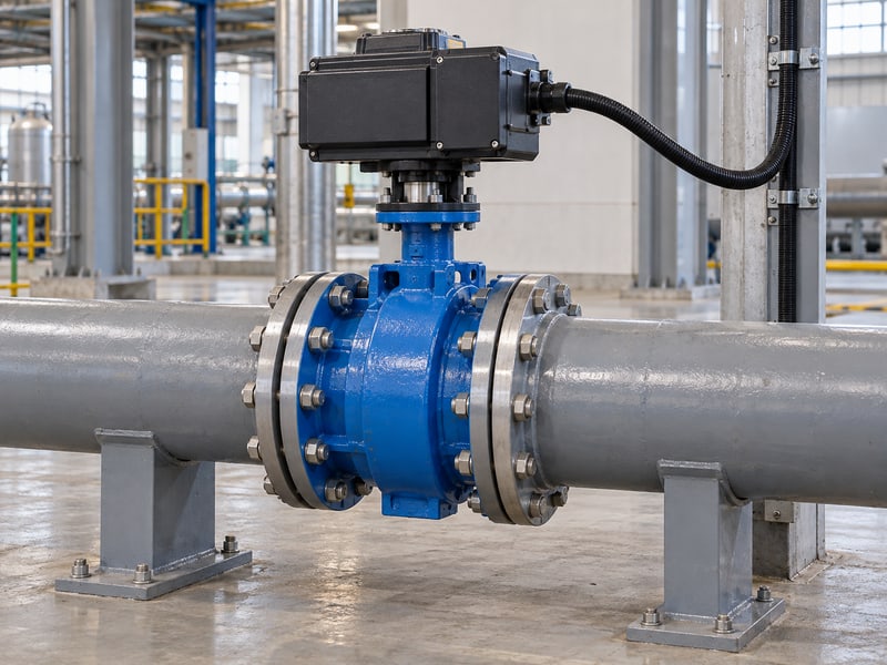
Commissioning butterfly valve actuator orientation checks mounting integrity, full travel, controls, and feedback in the completed installation. A bench check cannot reveal a cover blocked by site steelwork or a cable pressed against insulation.
What sequence should you follow?
Check the finished assembly before applying operating energy. Confirm mount fasteners, coupling retention, supports, enclosure closure, and cleared work areas. Follow the valve and actuator manuals for the permitted unpressurised functional check before the project procedure introduces process conditions.
- Inspect mounting and connection records.
- Check approved endpoint and torque settings.
- Confirm local, remote, and failure responses.
Do not drive past a stop to obtain a closed signal, and do not increase torque settings to overcome unexplained resistance. Disc interference, flange distortion, or incorrect indexing requires investigation; the valve's approved directional pressure rating also remains independent of actuator position.
What proves the installation is ready?
Key takeaway: Release requires mechanical travel and controls to agree under the approved commissioning conditions. Record unresolved faults before any operational handover.
| Check | Release evidence |
|---|---|
| Mounting | Inspection record |
| Movement | Accepted functional result |
| Controls | Confirmed signal agreement |
Complete the commissioning record against the actual assembly. Keep the valve out of automatic service until discrepancies are closed.
10. What butterfly valve actuator orientation details aid service?
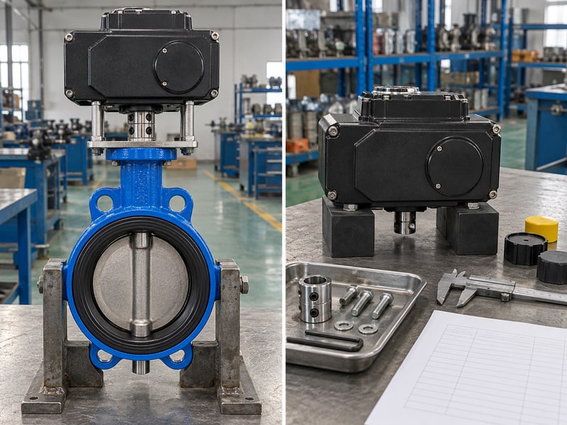
A useful butterfly valve actuator orientation specification includes the installed geometry, removal space, energy isolation points, and approved operating settings. Those records help maintenance replace a drive without repeating the original layout decisions.
What should procurement request?
Reserve the removal path as well as the working space. A cover may open in place while the complete actuator cannot lift clear of the stem. Request the assembly mass, lifting instructions, bracket arrangement, coupling details, and accessory configuration with the selected valve.
- Supply media and maximum closing differential.
- Identify minimum air or electrical supply.
- Mark controls, access, and removal limits.
Include operating frequency and external conditions in the enquiry. They let the supplier review torque, accessories, and maintenance access for the actual duty rather than matching an operator solely by mounting flange size.
Which records support replacement?
Key takeaway: Keep the approved orientation and drive settings with the valve maintenance file. A replacement needs mechanical and control compatibility checks before installation.
| Record | Maintenance use |
|---|---|
| Assembly drawing | Position and removal route |
| Drive details | Torque and supply match |
| Settings sheet | Travel and feedback recovery |
Send RUITO your duty data and marked layout to review the valve and drive arrangement; contact us today with the proposed mounting position. Request confirmation of access, coupling fit, and operating requirements before purchase.
FAQ
Q1: Can I rotate an actuator by a quarter turn?
Only if the approved assembly permits it. Check the mounting, coupling indexing, accessories, and travel verification procedure before changing its position.
Q2: What's the best side for electrical cable entries?
Use a permitted entry position that suits the site exposure. Approved glands, cable support, cover seals, and the manufacturer's drainage requirements all affect protection.
Q3: How do I know if the coupling is fully engaged?
Check the specified dimensions and insertion length. A fully tightened mounting flange does not reveal whether the drive insert has enough engagement.
Q4: Can a mounting interface guarantee actuator compatibility?
No. You must also confirm output torque, stem limits, drive shape, axial fit, travel, energy supply, and controls for the selected assembly.
Q5: Can I rely on a closed feedback signal after re-clocking?
Only after verification. Compare the signal with the approved actual disc position and confirm both endpoints through the commissioning procedure.