
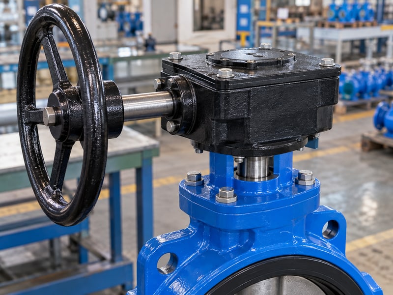
Fix butterfly valve gearbox orientation by checking drive engagement, approved mounting loads, and reliable travel indication. A worm gearbox may fit beside a pipe yet leave its coupling misaligned or its stops incorrectly set. Use the valve assembly drawing and gearbox manual to check the proposed position before installation or re-clocking.
1. What defines butterfly valve gearbox orientation?
The approved assembly drawing defines butterfly valve gearbox orientation by locating the gearbox housing and input shaft around the valve stem. Its reference view must also distinguish the stem axis from the direction of process flow.
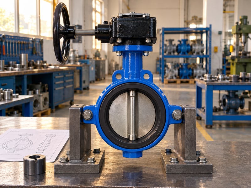
What should the drawing identify?
Mark the housing position against a defined view. A description such as left-hand mounting is incomplete unless you state where the observer stands. Include the input shaft, pointer, stop screws, and mounting face so workshop and site teams can identify the same arrangement.
- State the viewing direction.
- Show the input shaft centreline.
- Mark travel and service clearances.
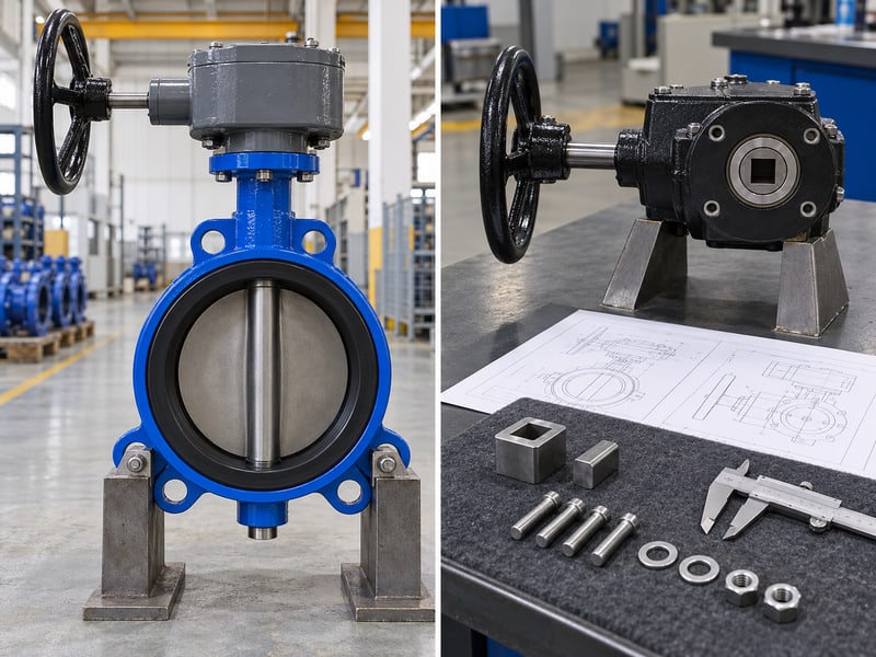
The gearbox drawing should match the supplied valve stem and adapter, including any keyway or square-drive index. The worm, gear wheel, output connection, and housing work as one drive assembly. A similar-looking housing from another size or revision can have a different output bore, height, or stop arrangement.
Which reference should the installer use?
Key takeaway: The assembly drawing ties the housing position to a specific valve and gearbox. A sketch of the pipe alone cannot establish drive compatibility.
| Reference | Purpose |
|---|---|
| Assembly view | Housing location |
| Drive detail | Bore and stem match |
| Site layout | Installed clearance |
Request the complete operator arrangement with the quotation. Check its revision against the supplied assembly before mounting it.
2. Can butterfly valve gearbox orientation be changed?
Butterfly valve gearbox orientation can be changed only through a mounting arrangement and procedure approved for the selected assembly. Some gearboxes permit specified clock positions, while others need different drive parts or mounting hardware.
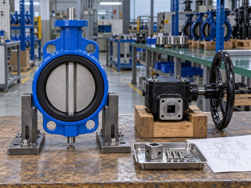
What must remain correct after re-clocking?
Confirm allowable positions before dismantling the mount. Symmetrical bolt holes may offer apparent choices without establishing correct coupling engagement or indicator indexing. A new position can also obstruct stop adjustments or move the input shaft into a walkway.
- Confirm permitted housing positions.
- Review insert and indicator indexing.
- Check stop and fastener access.
Isolate and depressurise the process, then follow the approved method for preventing unintended disc movement. A manual gearbox can retain torque from the valve or connected drive; do not loosen its mount on a pressurised assembly or use re-clocking as an access shortcut during operation.
What should a change request contain?
Key takeaway: Re-clocking requires approval of the drive, mounting, and travel arrangement together. Site convenience alone cannot establish whether the new position will function correctly.
| Proposed change | Review |
|---|---|
| Housing rotation | Approved clock positions |
| Adapter replacement | Fit and load capacity |
| Indicator reset | Actual disc reference |
Send the proposed view and clearance measurements for review. Include the manufacturer's verification steps in the work instruction.
3. How does butterfly valve gearbox orientation affect drive fit?
Correct butterfly valve gearbox orientation keeps the output bore aligned with the stem and maintains the specified engagement length. Misalignment or an incorrect adapter can damage the drive even when every mounting bolt reaches its final position.
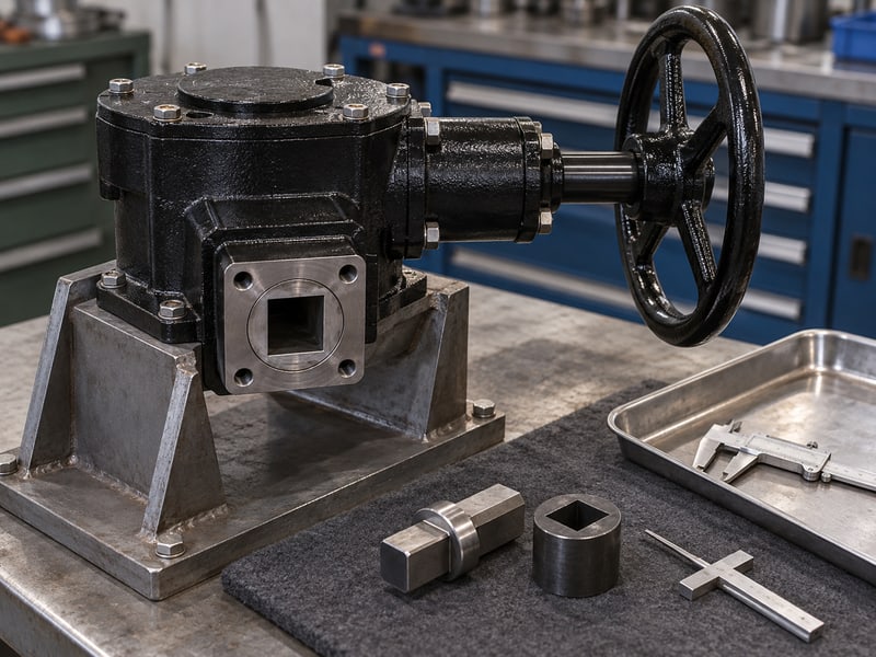
Which dimensions control engagement?
Check the drive fit before tightening the mount. Compare stem projection, bore depth, key length, adapter height, and axial clearance with the approved dimensions. A stem that bottoms in the output bore can prevent the mounting faces from seating correctly.
- Match square, key, or spline geometry.
- Confirm the required engagement length.
- Check clearance and retention provisions.
An ISO 5211 interface defines mounting features where applicable; it does not guarantee torque suitability, drive fit, or interchangeable operators. When reviewing flanged butterfly valves, request the actual stem detail and gearbox arrangement alongside the pipeline flange drawing.
What fit should be accepted?
Key takeaway: The output connection needs enough engagement without unintended axial or side loading. Tightening bolts cannot correct an incorrect drive stack height.
| Feature | Acceptance basis |
|---|---|
| Bore profile | Approved stem match |
| Engagement | Specified contact length |
| Axial clearance | Assembly drawing |
Measure the relevant parts before assembly. Stop if fastener force is needed to pull the housing onto its mounting face.
4. What loads affect butterfly valve gearbox orientation?
Gearbox weight, overhang, input force, and operating torque affect the mounting loads associated with butterfly valve gearbox orientation. Moving the housing around the stem can change bending reactions without changing the valve's required operating torque.
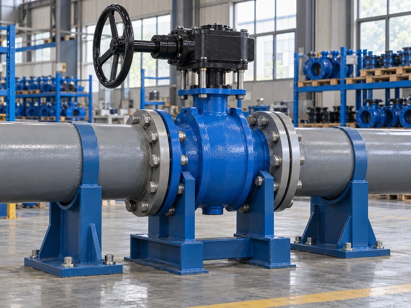
Where do the reactions go?
Trace the load through the bracket and valve neck. The output torque passes through the drive and housing mount, while an overhanging housing adds a weight-related bending moment. A bracket that flexes can introduce misalignment between the output bore and stem under operating load.
- Confirm housing mass and centre of gravity.
- Check bracket stiffness and bolt specification.
- Review external forces on the input shaft.
Use the approved support arrangement and account for pipe movement or vibration. A rigid site prop may push load into the assembly as piping heats or moves; lifting, carrying, or supporting a complete valve by its gearbox can also damage its mounting connection.
What should the load review record?
Key takeaway: A mounting review must cover weight and operating reactions. Torque capacity alone cannot demonstrate that the housing is adequately supported.
| Load | Check |
|---|---|
| Housing weight | Overhang and bracket |
| Output reaction | Mount fasteners |
| External input force | Shaft and bearings |
Ask engineering to identify any required support points. Inspect the installed mount before attempting the approved travel check.
5. What ratio suits butterfly valve gearbox orientation?
A suitable ratio lets the gearbox deliver required output torque within its input and duty limits; butterfly valve gearbox orientation must also leave room for that input arrangement. Ratio selection and housing position therefore need review together.
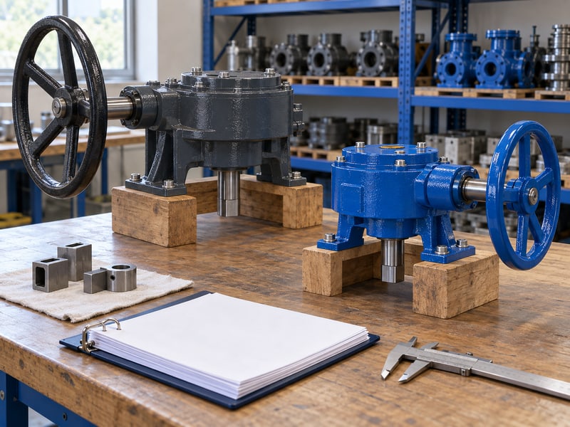
What determines operating effort?
Size the gearbox for the complete torque requirement. Breakaway, running, and seating torque can differ, and their values depend on the selected valve and service conditions. A higher reduction ratio can reduce required input torque but increases the input rotations needed for a given output movement.
- Obtain the valve torque requirements.
- Check gearbox output and input limits.
- Confirm operating frequency and duty.
For HVAC and district energy systems, include the actual circulating fluid and operating temperature in the enquiry. Glycol concentration, valve condition, and closing differential belong in the torque review; a nominal pipe size cannot provide those inputs.
Which ratings should procurement compare?
Key takeaway: Select ratio and operator geometry against the valve duty. A housing that fits the available space can still require unacceptable operating effort.
| Selection input | Reason |
|---|---|
| Valve torque | Required output |
| Input limit | Operator or drive load |
| Reduction ratio | Effort and rotations |
Request the supplier's sizing basis for the selected assembly. Check that its assumptions match the project duty before ordering.
6. How does butterfly valve gearbox orientation affect stops?
Butterfly valve gearbox orientation must leave its travel stops accessible and correctly related to the valve's approved endpoints. Stop screws limit output travel, but their presence does not prove that the disc reaches its intended open or closed position.
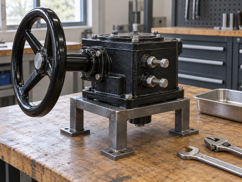
How should stop adjustment be approached?
Use the valve's approved endpoint procedure. Identify which stops belong to the gearbox and whether the valve or another drive also has travel limits. Their settings need coordination so one component does not force movement against another component's earlier stop.
- Identify open and closed stop functions.
- Check adjustment and locking access.
- Record the approved setting procedure.
Do not back out a stop to compensate for incorrect coupling indexing, and do not force the wheel beyond resistance to obtain tighter shutoff. The manufacturer must define the required seating position and adjustment method for the selected valve; a universal angular setting is unsuitable across different seat designs.
What should a setting record show?
Key takeaway: Stops must correspond to verified valve travel and remain secured. Adjustment should correct an approved setting, not conceal a mechanical interference problem.
| Component | Verify |
|---|---|
| Open stop | Intended open travel |
| Closed stop | Approved seating position |
| Locking device | Retained adjustment |
Identify the correct procedure before touching the stops. Record the accepted settings after verification and locking.
7. How does butterfly valve gearbox orientation show disc travel?
Reliable butterfly valve gearbox orientation keeps the indicator visible and indexed to actual disc position. An output pointer represents the gearbox setting, so its accuracy depends on the complete connection between gearbox and valve stem.
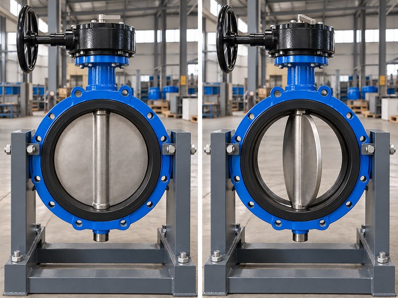
How can you verify indication?
Compare the pointer with an approved disc reference. Perform the comparison under the isolation conditions required by the valve manual. Where direct observation is unavailable, use the specified reference marks or inspection method rather than treating pointer alignment as proof of seat contact.
- Verify the open indication.
- Verify the closed indication.
- Check readability from the operating position.
In a hypothetical replacement job, a new gearbox could fit the stem while its pointer plate faces a wall. Repositioning the plate may restore visibility, but the team must still confirm its index and travel limits against the valve after assembly.
What makes indication usable?
Key takeaway: Indication needs both verified indexing and a readable location. Neither a clear pointer nor a correctly fitted housing can replace the endpoint check.
| Requirement | Check |
|---|---|
| Index | Actual disc reference |
| Endpoint | Approved travel position |
| Visibility | Normal operating location |
Mark the accepted open and closed references on the record. Resolve any disagreement before identifying the valve as available for service.
8. How is butterfly valve gearbox orientation protected?
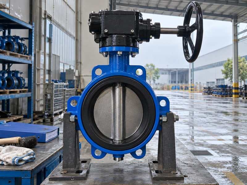
Suitable environmental protection keeps the housing, seals, coatings, and maintenance points compatible with the installed butterfly valve gearbox orientation. A changed position can expose a shaft seal to falling water or make a specified lubrication point unreachable.
What conditions need review?
Check the gearbox instructions for its installed attitude. Some designs have specified lubrication or vent arrangements, while sealed units may use different provisions. Do not assume every worm gearbox accepts the same lubricant quantity or service position.
- Identify splash, condensation, and dust exposure.
- Confirm coating and fastener suitability.
- Keep specified service points accessible.
For marine installations, external salt exposure differs from seawater flowing through the valve. The gearbox needs its own external protection review even when the valve is installed in a freshwater circuit, and applicable project documentation must cover the supplied assembly.
What protection details should be specified?
Key takeaway: Environmental suitability includes the gearbox and its accessories. Valve wetted-material compatibility cannot establish external operator protection.
| Exposure | Review |
|---|---|
| Spray or washdown | Seals and installed attitude |
| Salt atmosphere | Coating and fasteners |
| Maintenance | Lubrication access |
State the exposure conditions in the enquiry. Follow the specific lubrication and inspection schedule supplied with the gearbox.
9. How is butterfly valve gearbox orientation commissioned?
Commissioning butterfly valve gearbox orientation confirms mounting, engagement, travel stops, and indication in the finished installation. It should also confirm that operators can apply input force without striking surrounding equipment or loading the shaft sideways.

Which checks precede service?
Investigate resistance before applying more input torque. Check coupling fit, bracket alignment, and the valve's disc clearance using the approved isolated procedure. A tight section of travel can result from installation strain or interference, so a larger wheel is not a repair.
- Inspect mount and coupling records.
- Confirm full approved disc travel.
- Verify stops and indicator agreement.
Once mechanical checks are accepted, use the project commissioning procedure for service conditions and any required leakage verification. Gearbox position does not change the valve's pressure-temperature limit, directional closing rating, or flange sealing requirements; those remain specific to the selected model.
What should be handed over?
Key takeaway: Release the assembly when movement, stops, and indication agree. Keep the accepted conditions and findings with the valve records for later maintenance.
| Check | Record |
|---|---|
| Mounting | Fastener and fit inspection |
| Travel | Accepted endpoint verification |
| Service check | Project procedure result |
Complete the operator checklist on the installed valve. Close any unexplained resistance or indication fault before handover.
10. What butterfly valve gearbox orientation data aid purchase?
A useful butterfly valve gearbox orientation enquiry includes the valve duty, mounting geometry, input arrangement, and maintenance envelope. It gives the supplier enough information to review drive fit and operating loads before choosing an assembly.
Which inputs should you send?
Include the installed layout with the torque duty. State fluid composition, operating temperature, maximum closing differential, operating frequency, and external exposure. Mark the allowed housing position, input access, and removal route on the general arrangement drawing.
- Identify valve size and connection style.
- Provide stem and mounting details.
- Define input effort and access requirements.
For a replacement, include the original assembly identification and measured interface dimensions. Similar face-to-face length or pipe diameter cannot establish that a replacement gearbox will fit the existing stem or maintain the intended travel settings.
What records should remain with the valve?
Key takeaway: Keep the approved arrangement, ratings, and setting procedure together. Maintenance needs those details when replacing an operator or diagnosing a travel fault.
| Document | Use |
|---|---|
| Assembly drawing | Position and interface |
| Sizing record | Torque and input limits |
| Setting instructions | Stops and indication |
Send RUITO the duty and layout to review the valve and manual drive arrangement; contact us today with your proposed housing position. Ask for confirmation of mounting fit, access, and operating limits before placing the order.
FAQ
Q1: Can I turn the gearbox housing without moving the valve?
Only when the approved procedure allows it. Isolate pressure, restrain unintended disc movement, and verify drive indexing and travel after the change.
Q2: Does a worm gearbox always hold its position?
No universal assumption is safe. Holding and back-driving behaviour depend on the selected design, loads, wear, and any specified locking provisions.
Q3: What's the best gearbox ratio for a large valve?
Use the ratio selected for its actual torque duty. Input limits, operating rotations, frequency, and access also need review.
Q4: Can I adjust the closed stop to cure leakage?
Only through the approved diagnostic and adjustment procedure. Leakage can come from seat damage, interference, or incorrect indexing rather than a stop setting.
Q5: How do I know if the replacement gearbox will fit?
Compare the approved interface and drive dimensions. Confirm engagement, torque ratings, mounting loads, travel, indication, and operating access before installation.