
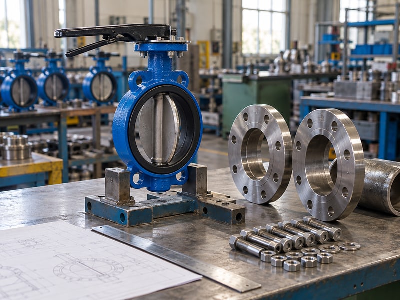
Fix butterfly valve installation orientation mistakes by checking pressure direction, mounting limits, flange alignment, and disc clearance against the model instructions. During a shutdown, a valve can fit the bolt pattern yet bind after tightening. Prepare the joint and verify movement in stages before returning the line to service.
1. What sets butterfly valve installation orientation?
Butterfly valve installation orientation follows the supplied model's manual and approved installation drawing. Those documents must cover the actual seat, body style, nominal size, and operator. A generic checklist cannot settle directional pressure limits or the mounting positions of every assembly.
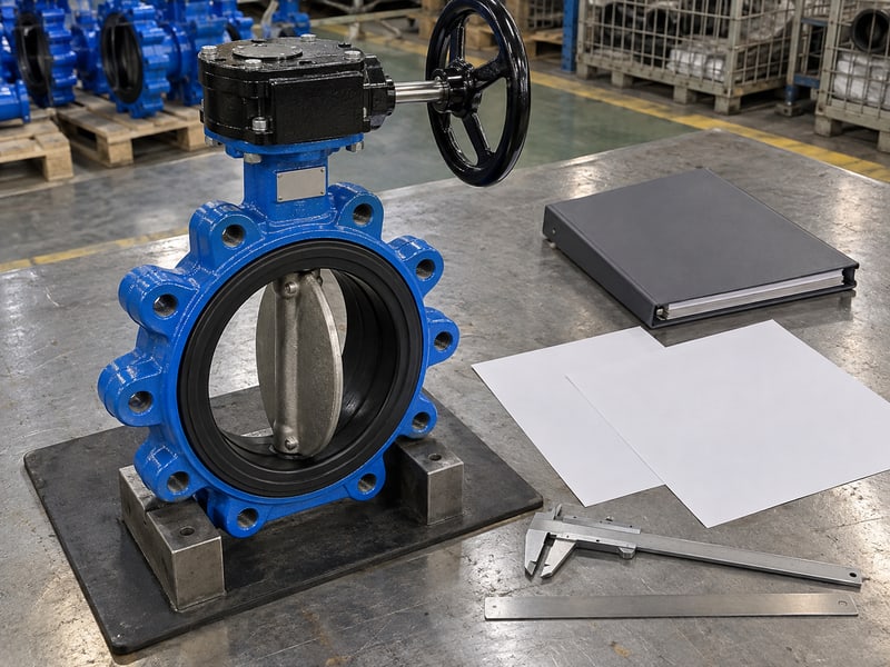
What should arrive before the shutdown?
Obtain the installation, operation, and maintenance manual, or IOM, with dimensional and directional data. Match the nameplate with the order. Check working limits and closed differential in both directions.
- Confirm valve identification and document revision.
- Record approved flow or pressure face.
- List permitted shaft and drive positions.
Release the paperwork before opening the line. A crew cannot resolve an undocumented pressure-side requirement by inspecting a symmetric-looking casting. Send photographs and the piping elevation to the supplier while the system remains available for planned work.
How do you define an installation hold point?
Require the supervisor to verify identity, direction, and clearances before final bolting. Hold the installation if the delivered assembly differs from the approved drawing. Key takeaway: a model-specific hold point catches configuration errors while the valve remains easy to remove.
| Item | Required evidence |
|---|---|
| Identification | Matching nameplate and order |
| Direction | Model instruction |
| Mounting | Approved assembly drawing |
Place the verified documents beside the installation work pack.
2. How is butterfly valve installation orientation prepared?
Butterfly valve installation orientation should be checked after safe isolation, depressurization, and preparation of the work area. Residual fluid, trapped pressure, and automatic movement can injure the crew during positioning. Follow the site's isolation procedure and verify the line condition before removing any connection.
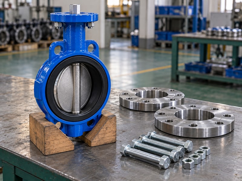
What needs isolating besides the pipe?
Control electrical, pneumatic, hydraulic, and stored spring energy according to the drive instructions. A closed valve does not establish safe isolation by itself. Check connected branches and the possibility of pressure returning from another source before loosening flange bolts.
- Drain and vent through approved points.
- Verify the isolated section's condition.
- Secure automatic commands and stored energy.
Check both pressure sources before loosening bolts. A parallel pump, elevated tank, or bypass can pressurize the opposite side of a valve. Include those sources in the isolation plan rather than inferring pressure from normal flow direction.
How should you stage the assembly?
Support the pipe and protect seats and flange faces. Use designated lifting points, with suitable lifting equipment. Key takeaway: controlled isolation and support let you position the valve without unexpected movement or load.
| Preparation | Check |
|---|---|
| Fluid isolation | Depressurized and drained |
| Drive isolation | Energy controlled |
| Handling | Approved lifting points |
Complete the isolation and handling checks before bringing the valve in.
3. What confirms butterfly valve installation orientation?
Butterfly valve installation orientation is confirmed by matching documented body marks with the intended pressure side and shaft position. An arrow's meaning must come from the model instructions. The absence of an arrow does not establish equal shutoff performance in both directions.
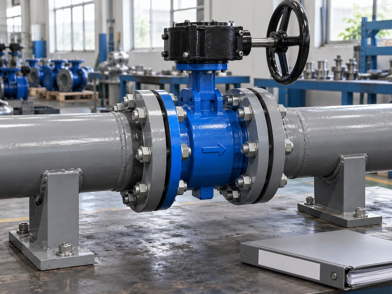
Which operating conditions can reverse pressure?
Consider shutdown, downstream tank head, alternate pump operation, and backfeeding during maintenance. Some models permit reverse flow but have a different reverse shutoff differential. Record the required conditions so a preferred direction is not mistaken for permission at every pressure.
- Compare body marks with the piping drawing.
- Confirm forward and reverse shutoff requirements.
- Check that the operator remains within its mounting limits.
Mark the confirmed face before insertion. Use the site's approved identification method and preserve factory labels. A removable field note can help the lifting crew align the body while permanent records retain the model's requirements.
What if access favors another position?
Review permitted operator clocking or revised supports before rotating the body. A convenient gearbox position can coexist with an unsuitable pressure face. Key takeaway: confirm body direction, shaft axis, and access separately before clamping.
| Feature | Confirm against |
|---|---|
| Pressure face | Directional rating |
| Shaft axis | Permitted mounting |
| Operator position | Access and drive limits |
Photograph the confirmed arrangement for the installation record.
4. Which flanges suit butterfly valve installation orientation?
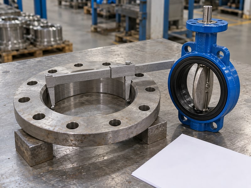
Butterfly valve installation orientation requires compatible flange faces, drilling, pipe bore, and face-to-face length. Nominal bore and pressure class alone do not prove a fit. The disc may project beyond the body and encounter a flange bore, lining, or adjacent component during rotation.
What should the fitter measure?
Compare companion flanges with the approved disc envelope. Check linings, weld penetration, reducers, and sleeves. The wafer butterfly valve page describes the compact arrangement; installation needs a size-specific clearance check.
- Verify drilling pattern and mating face type.
- Measure the available bore near each disc projection.
- Check face-to-face length against the spool gap.
Measure where the disc moves. A flange with suitable bolt holes can still have an internal shoulder inside the required opening envelope. Review the full sweep rather than checking clearance only with the disc closed.
How do you handle a mismatch?
Stop and resolve the incompatible flange or spool through the approved engineering process. Do not grind the disc edge, trim a seat, or force an undersized bore around the valve. Key takeaway: dimensional compatibility includes the moving disc envelope as well as the stationary body.
| Dimension | Reason for checking |
|---|---|
| Flange bore | Disc clearance |
| Drilling pattern | Bolt alignment |
| Spool gap | Correct body fit |
Record measured clearances before inserting the assembly.
5. Do seals affect butterfly valve installation orientation?
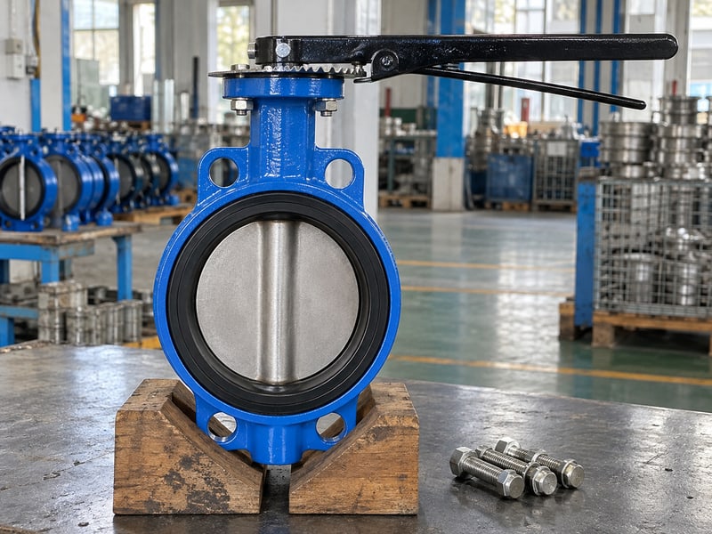
Butterfly valve installation orientation must follow the model's gasket and flange-face instructions. Some resilient seats seal against companion flanges without separate gaskets; other constructions require specified gaskets. Adding or omitting one changes compression and may affect disc movement or flange sealing.
How should sealing surfaces be prepared?
Remove old gasket remnants and debris using a method compatible with the flange, coating, and liner. Inspect for cuts, corrosion, raised welds, and damage that could prevent uniform contact. Keep tools and lifting slings clear of resilient seats and liner flares.
- Confirm whether separate gaskets are required.
- Verify gasket type, thickness, and placement where specified.
- Use lubricants only where the manual permits them.
Use the specified sealing arrangement. A familiar gasket practice from another valve can distort a resilient seat or a chemical liner. Review each construction independently, including permitted flange face and bolt-tightening instructions.
Does seat material change the review?
Material compatibility includes actual fluid composition and temperature. EPDM water-service seating does not establish mineral-oil or steam suitability. Key takeaway: correct flange sealing starts with the model's materials and assembly instructions.
| Construction | Verify |
|---|---|
| Resilient seat | Separate gasket instruction |
| Specified gasket | Material and thickness |
| Lined body | Flare compression limits |
Close any gasket uncertainty before tightening the joint.
6. How is butterfly valve installation orientation positioned?
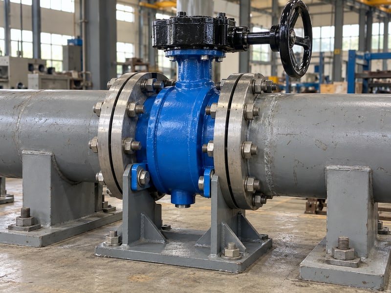
Butterfly valve installation orientation is maintained by aligning and supporting the pipe before carefully centering the body. Flange bolts should secure a prepared joint rather than pull misaligned pipework into place. Follow the model's insertion position for the disc and required flange separation.
What prevents seat damage during insertion?
Provide enough controlled clearance to slide the body into position without scraping the sealing faces. Many resilient designs specify a partly closed disc for insertion, but the exact position comes from their IOM. Secure the assembly against unintended rotation while the crew handles it.
- Check flange faces are parallel and aligned.
- Keep lifting loads on approved points.
- Center the valve using the prescribed guides or method.
Correct pipe alignment before drawing the flanges together. Pipe spring, uneven support, or an incorrect spool length can load the body during tightening. Resolve that condition through the piping plan without using the valve as an alignment tool.
How do you check the preliminary fit?
Fit specified bolts loosely and verify centering, direction, access, and nearby disc clearance. Key takeaway: a centered valve between supported, parallel flanges provides a controlled starting point for final bolting.
| Fit check | Acceptable finding |
|---|---|
| Pipe alignment | No forced displacement |
| Body centering | Disc envelope clear |
| Temporary support | Stable assembly |
Have the supervisor approve the preliminary fit before final tightening.
7. What bolts suit butterfly valve installation orientation?
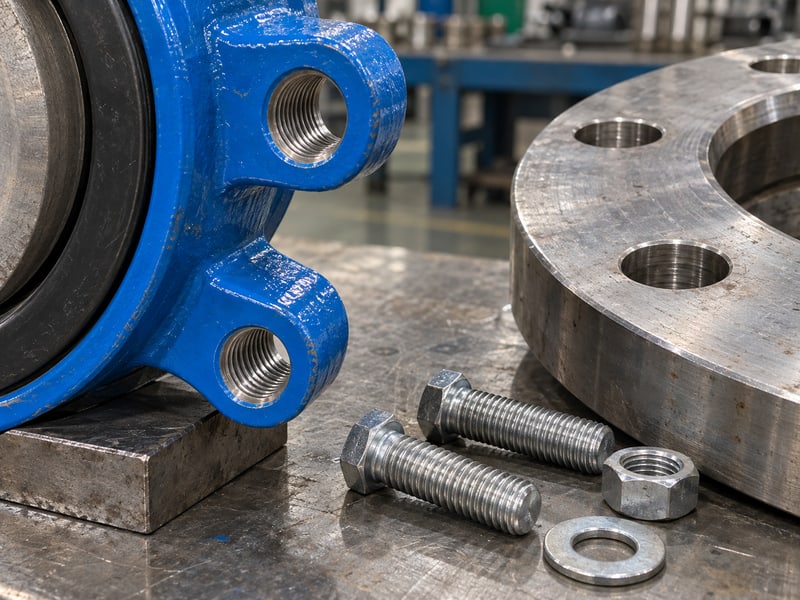
Butterfly valve installation orientation must use the specified bolt dimensions, engagement, and tightening method. Wafer, lug, and double-flanged bodies attach differently. Their connection style does not override the model's thread limits, allowable loads, or gasket requirements.
What changes with a lug body?
Check bolt length and thread engagement so fasteners neither bottom in tapped holes nor interfere with opposite-side hardware. RUITO's lug butterfly valve options require configuration-specific review for end-of-line duty. Independent bolting does not by itself establish permission to remove a downstream flange under pressure.
- Match bolt grade and dimensions with the installation specification.
- Confirm thread engagement for each side.
- Keep flange face loads within the approved arrangement.
Check engagement before applying torque. A bolt that reaches a nominal torque after bottoming has not necessarily clamped the flange correctly. Verify fit, then tighten using the prescribed sequence and values for the actual joint.
What should the installer record?
Record torque values, tightening sequence, and required intermediate movement checks. Watch for body displacement as clamp load increases. Key takeaway: correct engagement and controlled clamp load protect the connection and valve movement.
| Body style | Connection check |
|---|---|
| Wafer | Through-bolt fit and centering |
| Lug | Thread depth and engagement |
| Double flange | Each joint's specification |
Record final bolting completion against the valve tag.
8. How is butterfly valve installation orientation cycled?
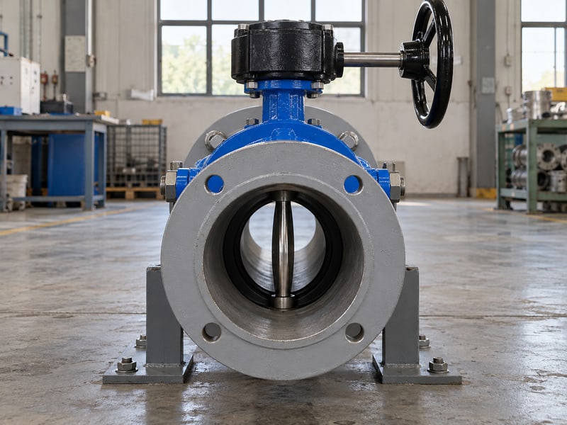
Butterfly valve installation orientation should be checked through the required disc travel after final mounting and before pressurization. Use the model's safe manual or powered verification procedure. An indicator showing open does not prove that the disc clears the pipe throughout its movement.
What should you watch during movement?
Keep personnel and tools away from the bore and moving drive parts. Observe smooth movement, end-position correspondence, and clearance using an approved inspection method. A rising operating effort after bolting can point toward seat compression, miscentering, or mechanical interference.
- Verify disc travel and external indication agree.
- Check controls and guards clear moving parts.
- Record abnormal resistance or contact.
Stop when movement becomes abnormal. Do not add a pipe extension to the handle or increase actuator force to overcome an unknown obstruction. Safely isolate the drive and inspect the installation before deciding whether adjustment or removal is needed.
Can end stops solve an interference problem?
Stops cannot solve disc interference with a flange or liner. Adjust approved end positions through the model instructions and verify movement afterward. Key takeaway: free, correctly indicated travel is an acceptance check before commissioning.
| Observation | Response |
|---|---|
| Smooth full travel | Record verification |
| Unexpected resistance | Stop and inspect |
| Indicator mismatch | Verify indexing |
Document the movement check before authorizing line filling.
9. How is butterfly valve installation orientation tested?
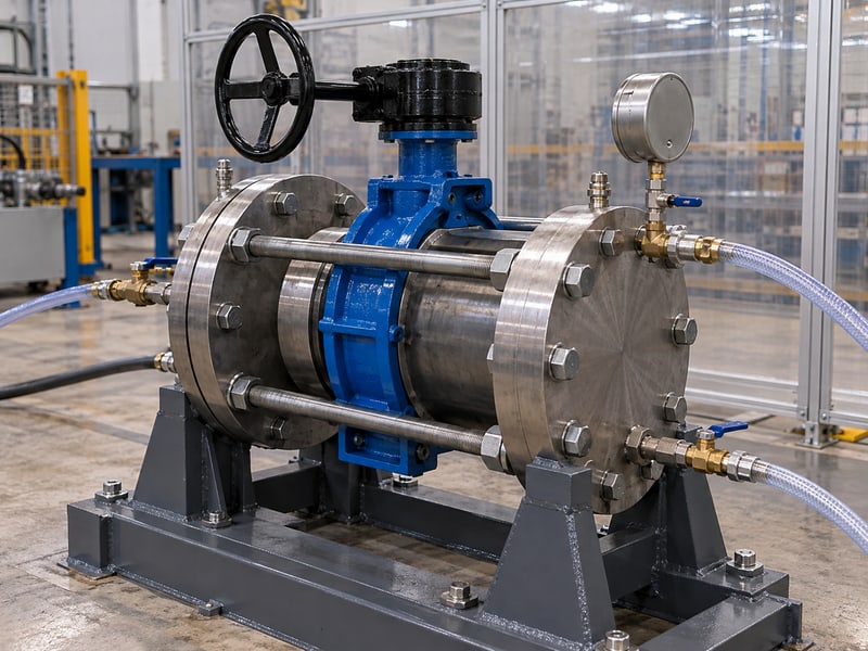
Butterfly valve installation orientation is commissioned through the project's approved filling, pressure, leakage, and functional checks. Test conditions must stay within the permitted limits of every included component. Factory shell or seat test pressures do not authorize the same pressures for routine operation.
What goes into the test plan?
Specify test medium, pressure, direction, hold conditions, acceptance criteria, and valve position. Identify which components are isolated or included and how trapped air will be vented. The approved plan should address supports and any differential imposed across a closed disc.
- Fill and vent through designated points.
- Check external joints and shaft seals.
- Verify operation at the agreed commissioning conditions.
Use the approved field test limits. A pipe test requirement can exceed a valve seat's allowable differential or another component's rating. Resolve that conflict before applying pressure, using the project engineer's approved isolation or test arrangement.
What if leakage appears?
Depressurize before changing bolts, stops, or packing settings. Distinguish flange, shaft, and seat leakage. Key takeaway: record the leakage location and conditions so corrective work addresses the actual fault.
| Leakage location | Check after safe isolation |
|---|---|
| Flange joint | Face and sealing arrangement |
| Shaft seal | Model service instructions |
| Closed disc | Seat, direction, and stops |
Retain pressure and functional records in the commissioning package.
10. Who signs off butterfly valve installation orientation?
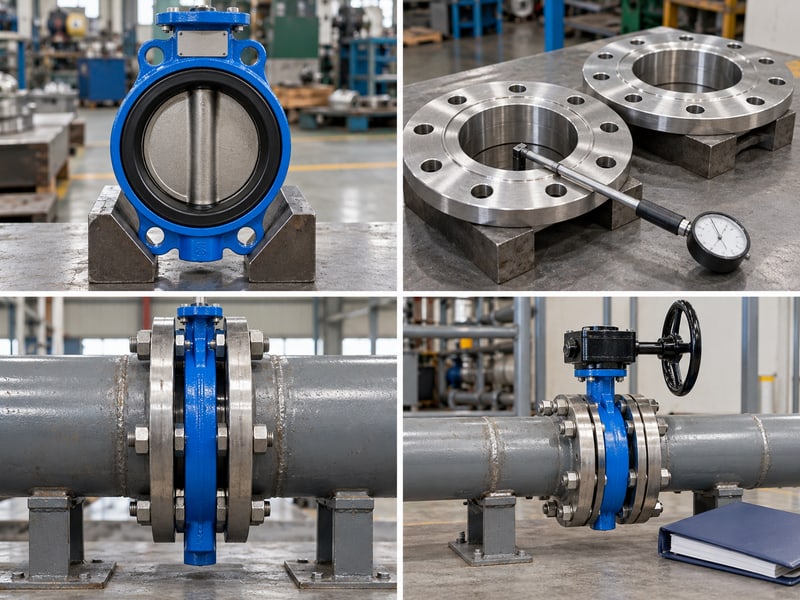
Butterfly valve installation orientation is signed off by the project's designated installation and commissioning personnel after documented checks pass. The signoff should identify the delivered assembly and approved layout. Keep unresolved deviations visible so operations staff can judge readiness for service.
What should operations receive?
Provide the final drawing, model IOM, tag, pressure-side information, and acceptance records. Include supports and access requirements. Hand over the arrangement the crew installed. Record approved field changes.
- Confirm direction and permitted mounting.
- Retain flange, gasket, and bolt information.
- Record commissioning acceptance and service limits.
What should you send for technical review?
RUITO can review configuration, interface drawings, and installation documents when you provide the fluid, operating limits, closed differential, and companion flange details. Send photographs or a marked spool drawing for a replacement. Key takeaway: matching documents, measured clearances, and recorded commissioning make the installation reviewable; contact us today with your work pack.
| Handover record | Purpose |
|---|---|
| Final layout | Reproduce installation |
| Model instructions | Maintain assembly |
| Commissioning results | Confirm acceptance |
Store the approved package with the site's valve register.
Frequently asked questions
Q1: Can I use extra gaskets on a resilient seat?
Only if its manual requires them. Extra compression can interfere with sealing or movement.
Q2: Can I pull misaligned flanges together with bolts?
No. Correct pipe alignment and support before clamping the valve into place.
Q3: How do I know the disc has enough clearance?
Compare measured bores with the model drawing and verify full travel through the approved procedure.
Q4: Can I use a lug valve at an open pipe end?
Only with a verified end-of-line rating for that configuration, pressure, temperature, and connection arrangement.
Q5: What should I do if the valve binds after tightening?
Stop. Safely isolate it and inspect centering, flange compatibility, seat compression, and disc clearance.