
Avoid costly butterfly valve actuator parts mistakes by matching the actuator identification, valve interface and approved spare-parts list before ordering. A replacement coupling can fit the bolt pattern yet bottom out on the shaft. A similar-looking seal kit can contain a different elastomer. Both problems can leave a repaired assembly unable to complete its stroke. Use the checks below to separate valve components from actuator components, confirm compatibility and prepare a parts request that a supplier can verify.
1. What do butterfly valve actuator parts include?
The assembly includes a drive mechanism, a connection to the valve shaft and any specified control accessories. When identifying butterfly valve actuator parts, separate the actuator internals from the valve body, disc, stem and seat. A pneumatic actuator may contain pistons, a pinion, bearings, seals and a spring package; an electric actuator instead uses its own motor, transmission and control arrangement. The exact list depends on the supplied design.
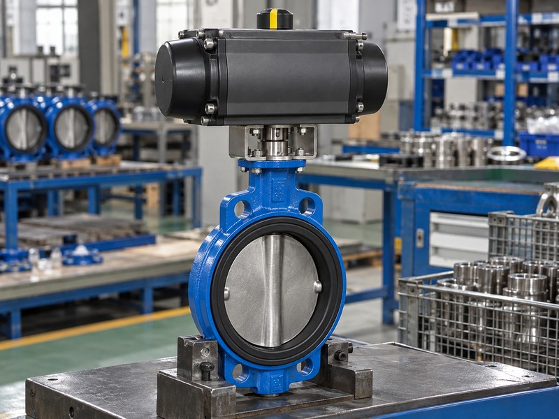
Where should identification begin?
Photograph the valve and actuator identification separately. Record the assembly tag, actuator manufacturer, complete model, serial number and any build or revision reference supplied with the unit. A plant tag identifies an installation position, so it may remain unchanged after someone replaces the actuator. Compare that tag with the equipment currently fitted before accepting an old stores record.
- Identify the valve and actuator as separate items.
- Mark accessories that belong to the complete assembly.
- Request a parts drawing for the exact actuator build.
| Item group | Typical examples | Matching evidence |
|---|---|---|
| Valve | Body, disc, stem, seat | Valve parts drawing |
| Actuator | Drive, bearings, seals | Actuator model and revision |
| Interface | Bracket, coupling, fasteners | Assembly drawing |
A photograph supports identification, but the approved parts list determines which replacement belongs in that actuator.
2. How do the body and disc affect actuator loading?
The body and disc define the valve geometry and operating loads that the actuator must handle. Check butterfly valve actuator parts against the actual valve configuration, including size, seat, disc construction and service conditions. Nominal diameter alone cannot establish the required output torque. Two valves with the same flange size can have different seating loads, shaft arrangements or permitted differential pressures.
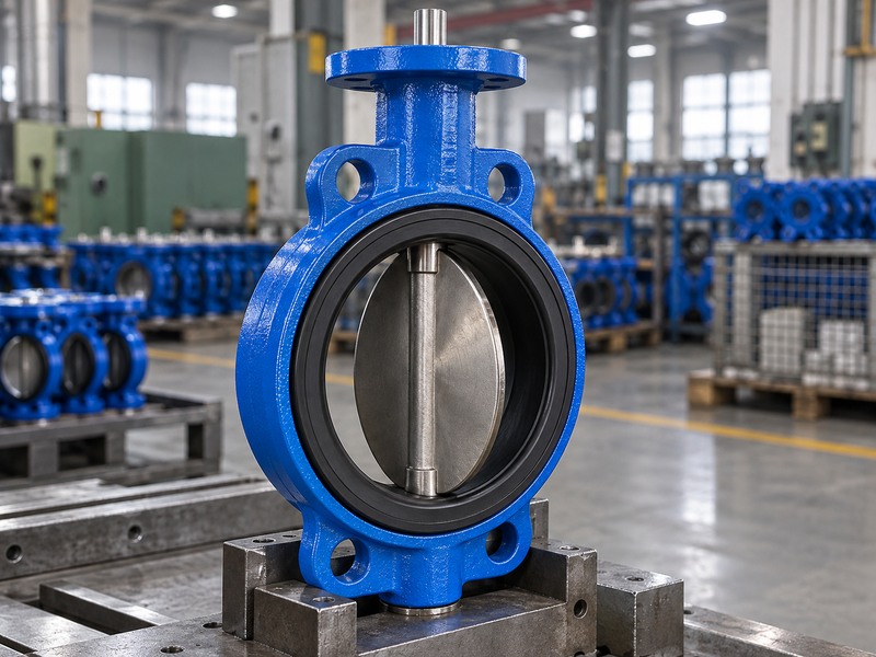
What should you check on the valve?
Compare the installed body style with its assembly drawing. Wafer, lug and flanged bodies need their own installation and support checks, while disc clearance depends on the complete pipe connection. If a disc rubs against an unsuitable mating bore, a larger actuator will not correct that interference. Investigate the mechanical obstruction before changing the drive or raising an available torque setting.
- Record the body connection and disc arrangement.
- Check the approved operating differential pressure.
- Inspect for fouling, corrosion or mechanical interference.
| Observed issue | Check before ordering | Consequence for parts |
|---|---|---|
| Disc rubbing | Mating bore and alignment | Correct the installation |
| Heavy operation | Seat condition and deposits | Diagnose the valve load |
| Changed service | Pressure, temperature, medium | Recheck the assembly duty |
Keep the valve service data with the actuator request so the supplier can assess the complete load path.
3. Which shaft and coupling dimensions must match?
The shaft profile, engagement depth, mounting geometry and angular indexing must match the approved assembly. Review butterfly valve actuator parts with dimensioned interface drawings rather than a photograph of the bolt holes. A common mounting pattern does not establish that the shaft drive fits. Check the bracket height and clearance around the coupling before confirming that an actuator can mount directly.
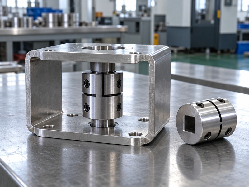
How can a fitting coupling still be wrong?
A square socket can slide over a shaft yet provide too little engagement for the specified load. A coupling can also bottom out before the mounting faces meet, leaving fasteners to pull the assembly into position. Neither condition should be corrected by tightening the mounting bolts harder. Ask the supplier to confirm the intended engagement, retention method and assembly clearances on the drawing.
- Measure the shaft profile and exposed shaft length.
- Confirm the mounting pattern and bracket height.
- Match the valve position with the actuator indexing.
| Interface feature | Evidence to request | Release condition |
|---|---|---|
| Shaft drive | Profile and dimensions | Correct mating geometry |
| Coupling | Engagement and retention | Approved load transfer |
| Bracket | Drawing and fastener schedule | Faces align without force |
Retain the confirmed interface drawing with the spare coupling; it prevents a later buyer from ordering by appearance alone.
4. How does the valve seat affect replacement decisions?
The seat affects sealing, operating resistance and compatibility with the process medium. Selecting butterfly valve actuator parts therefore requires the valve seat specification, even when the requested item sits above the valve. Seat material names need their complete application limits. Do not transfer one elastomer's temperature or chemical suitability to another compound, or combine maximum limits from different valve configurations.
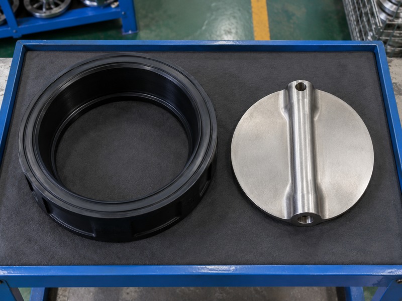
When should you investigate the seat?
Investigate the seat if the valve becomes difficult to move, fails its agreed shutoff test or shows visible damage during an approved inspection. Those symptoms can also come from deposits, misalignment or a changed process condition, so they do not prove that the actuator needs replacement. Record the evidence before requesting a new drive. If the seat is replaceable, follow the valve manufacturer's service method and use the specified replacement.
- Record the medium, concentration and cleaning chemicals.
- Check the working pressure and temperature together.
- Confirm whether the seat can be serviced on that model.
| Seat information | Why procurement needs it | Required record |
|---|---|---|
| Compound | Chemical compatibility | Approved material specification |
| Service conditions | Operating and sealing load | Current process data |
| Serviceability | Repair method and parts | Model-specific instructions |
Diagnose a valve-side fault before assigning the resulting load increase to a failed actuator component.
5. Which pneumatic actuator parts need model matching?
Pistons, pinions, bearings, seals and spring components require model-specific matching. Order butterfly valve actuator parts using the actuator build, action type and approved kit reference. Double-acting and spring-return versions may share an external appearance while using different internal arrangements. A seal kit listed for one size or revision should not be assumed to fit the next.
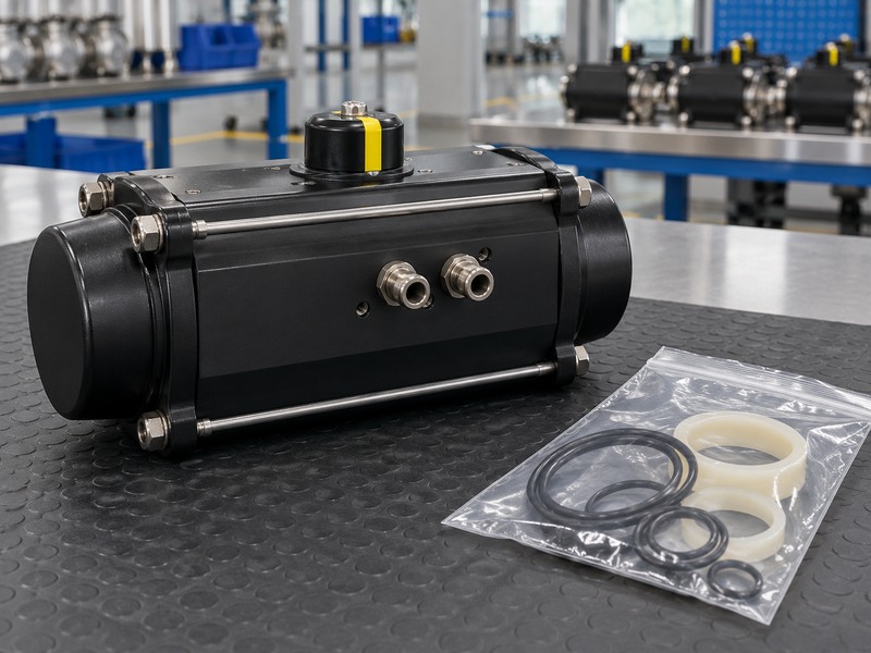
What should a pneumatic service request contain?
Provide the actuator's actual air supply conditions, required movement and failure response. Treat spring-return maintenance as a separate task under the manufacturer's procedure because stored spring energy can remain after the air supply is isolated. The published actuator maintenance instructions illustrate why the service method must follow the exact design. This buying checklist does not provide a disassembly procedure.
- Identify double-acting or spring-return construction.
- Specify the approved seal material and lubricant.
- Include the complete spring configuration when applicable.
| Part family | Match against | Avoid assuming |
|---|---|---|
| Seals | Kit reference and compound | Same colour means same material |
| Bearings | Size and revision | Similar dimensions prove fit |
| Springs | Approved actuator configuration | Loose springs are interchangeable |
Keep the ordered kit sealed and identified until the service team checks it against the job's approved parts list.
6. Which electric actuator parts require compatibility checks?
Motors, gear assemblies, switching devices and control boards must match the electric actuator's electrical and mechanical build. A request for butterfly valve actuator parts should include supply voltage, frequency where applicable, control signal, feedback arrangement and duty classification. A matching enclosure shape cannot establish electrical compatibility. Record environmental protection and any required hazardous-area approval before proposing a replacement component.
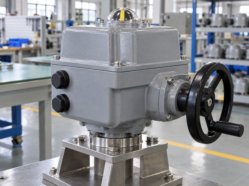
What information prevents an electrical mismatch?
Use the wiring diagram issued for the installed actuator. Similar terminal numbers can serve different functions across product families, and a replacement board may need approved configuration or commissioning. A manual override also does not prove that the actuator will move automatically after power loss. Specify the required loss-of-power response and verify whether the supplied assembly has the equipment needed to provide it.
- Copy the complete actuator identification and electrical rating.
- Attach the correct wiring diagram and revision.
- State the command, feedback and loss-of-power requirements.
| Requested part | Compatibility check | Acceptance evidence |
|---|---|---|
| Motor | Supply and duty | Approved replacement reference |
| Control board | Hardware and configuration | Supplier confirmation |
| Switch assembly | Function and adjustment | Commissioning record |
Route electrical work through qualified personnel and the equipment's isolation procedure; do not infer a wiring method from an article illustration.
7. How do solenoids and feedback devices fit the assembly?
Solenoids route the control air, while switches or transmitters report position according to their design. Include these accessories when checking butterfly valve actuator parts, but identify each accessory separately. An air-operated actuator does not need the same control arrangement in every installation. Match the required function, pneumatic interface, electrical supply and environmental rating before replacing a device.
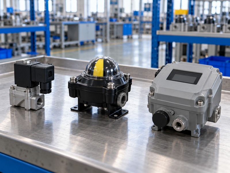
Which feedback signal does the process need?
Separate discrete open-or-closed indication from continuous position feedback and from a modulating positioner. They solve different control tasks. A switch that operates at the end of actuator travel confirms the switch setting; it does not independently prove that the valve seat seals. After service, check the disc-to-actuator relationship and verify feedback against the actual valve position under the approved test plan.
- Specify on/off operation or modulating control.
- Confirm the accessory supply and output signal.
- Record pneumatic porting and the intended failure response.
| Accessory | Main function | Separate verification |
|---|---|---|
| Solenoid valve | Routes control air | Porting and de-energized state |
| Limit switches | Discrete position indication | Cam setting and valve indexing |
| Positioner | Controls travel from a command | Calibration and feedback |
Retain the accessory identification with the actuator record so a complete assembly can be rebuilt without guessing its control functions.
8. How should torque and fail action be checked?
Check the required valve torque against the available actuator output throughout the relevant travel and operating conditions. Do not select butterfly valve actuator parts from one nominal torque value alone. Pneumatic output depends on the supplied air pressure, and spring-return output also depends on the approved spring arrangement. Check permitted loads for the valve shaft, coupling and mounting components as part of the same review.
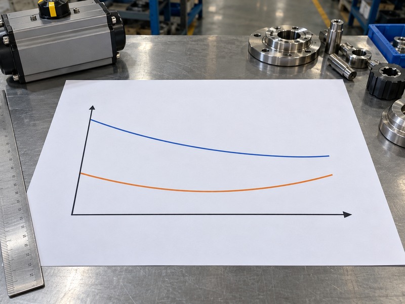
Which assumptions belong in the sizing record?
Record seating, unseating and running requirements as applicable to the valve and service. Use the supplier's sizing method and stated allowances; do not add a universal percentage to every torque table. A manufacturer's valve torque guidance can specify how its published values should be used. Treat air loss, electrical power loss and control-signal loss as separate events when defining the required response.
- Use the minimum available operating air pressure.
- Check the required movement and spring-driven stroke.
- Compare the selected output with permitted component loads.
| Review input | Source | Decision supported |
|---|---|---|
| Valve load | Approved duty-specific data | Required actuator output |
| Available output | Correct actuator performance data | Suitability across travel |
| Failure event | Process control requirement | Required final response |
In the schematic, blue represents available output and orange represents required valve torque. Neither curve contains sizing values; obtain approved performance data before releasing a replacement.
9. What checks reveal damage before reassembly?
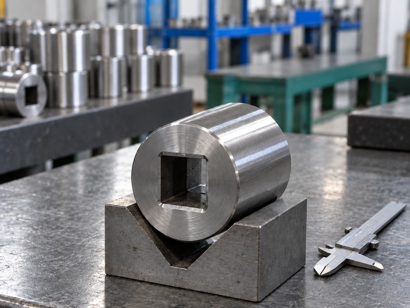
Identification, dimensional inspection and a documented condition check can reveal mismatched or damaged components before reassembly. Inspect butterfly valve actuator parts against the approved drawing and receiving plan. Check accessible drive surfaces for wear, corrosion, burrs and distortion. Keep suspect components separate until the responsible engineer decides whether they can be accepted, repaired or replaced.
How should you record an inspection finding?
Photograph the defect beside the component identification and describe its location. Measurements need an appropriate instrument and the tolerance from the applicable drawing; a caliper reading without an acceptance limit cannot establish conformity. Avoid grinding a coupling, modifying a shaft or substituting fasteners to make a mismatched kit fit. Those changes can alter engagement, retention or the load path that the assembly approval covers.
- Compare the received kit with its purchase reference.
- Record dimensions only against defined acceptance criteria.
- Retain damaged items until the failure investigation closes.
| Inspection finding | Record | Next action |
|---|---|---|
| Worn drive surface | Photos and measurements | Engineering disposition |
| Wrong kit reference | Packaging and order details | Resolve supply mismatch |
| Corroded hardware | Location and service history | Review approved replacements |
After an authorized repair, verify travel, indication and the specified failure response before returning the assembly to service.
10. What should a complete spare-parts order contain?
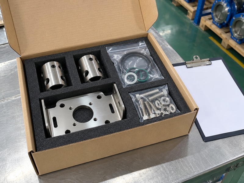
A complete order identifies the equipment, replacement scope, service conditions and acceptance documents. Request butterfly valve actuator parts as a defined kit or approved component list with quantities. State whether you need an actuator repair kit, an interface kit, accessories or a complete replacement assembly. Ask the supplier to flag any proposed substitution before manufacture or dispatch.
Which documents should travel with the kit?
Keep the quotation, approved parts list, interface drawing and applicable instructions under the same order reference. Specify material or inspection records only where the contract requires them, and agree on the functional checks needed after installation. For an overseas site, confirm packaging, storage instructions and identification that will remain readable when the carton reaches the maintenance store. A delivery date alone does not close the technical questions.
- Attach valve and actuator identification photographs.
- List each approved part, quantity and revision.
- Agree on documentation and acceptance checks before dispatch.
| Order field | Minimum useful detail | Supplier response |
|---|---|---|
| Equipment | Complete identification | Confirmed applicability |
| Replacement scope | Kit or individual items | Approved parts list |
| Interface and duty | Drawings and operating data | Reviewed compatibility |
Send your identification photos, interface dimensions and service conditions when you contact us. RUITO can review the requested valve configuration and clarify the supply scope before you place the order.
Frequently asked questions
Q1: Can I buy actuator parts using the valve size alone?
No. Valve size does not identify the actuator's internal build, output requirement or shaft interface. Provide both sets of equipment identification and the relevant parts drawing.
Q2: How do I know if a replacement coupling fits?
Confirm its profile, engagement, retention and mounting clearances against the assembly drawing. Matching the bolt pattern addresses only one part of the connection.
Q3: Can I replace pneumatic seals with similar-looking O-rings?
Use the specified seal kit or an approved equivalent. Appearance does not establish compound, dimensions, lubrication requirements or compatibility with the actuator's service.
Q4: What's the best way to confirm fail-close operation?
Test the defined failure event under an approved procedure. Specify whether you mean loss of air, power or signal, then verify the valve's response and position feedback.
Q5: Should I replace the actuator when the valve becomes stiff?
Diagnose the assembly before deciding. Seat condition, deposits, alignment and process changes can raise the operating load even when the actuator itself has no failed part.