
A double acting butterfly valve uses compressed air to drive its actuator in both opening and closing directions. You avoid most selection mistakes by separating that operating principle from the valve’s pressure, material, shutoff, and failure requirements. A common commissioning problem starts when a buyer assumes “double acting” also means automatic closure after air loss. Check the complete assembly and its control arrangement before using that assumption in a process design.
1. What does a double acting butterfly valve do?
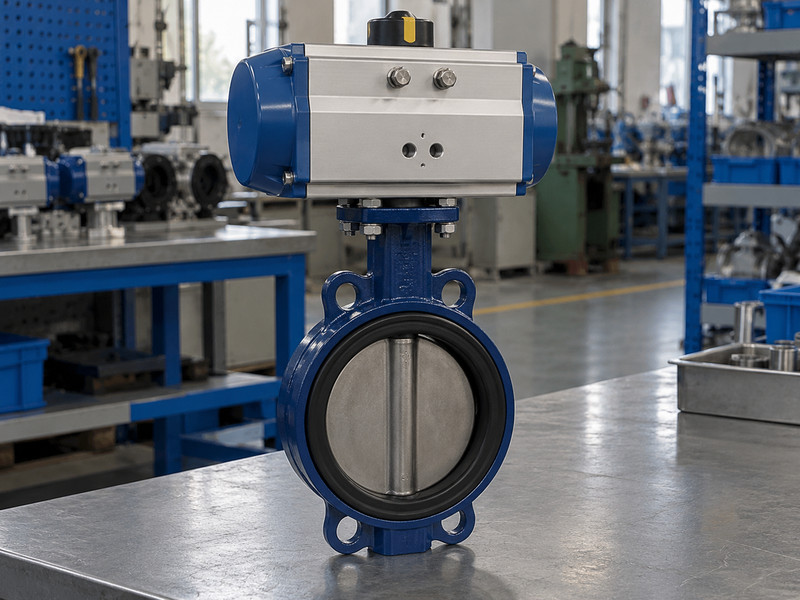
A double acting butterfly valve rotates a disc through a pneumatic drive to open, close, or, with suitable controls, regulate a flow path. Air supplies energy for movement in both directions. The actuator sits outside the process boundary; the body, seat, disc, and shaft remain responsible for containing and controlling the fluid.
Which specifications belong to each component?
Process pressure acts inside the valve, while instrument-air pressure acts inside the actuator. A suitable pneumatic supply does not establish the valve’s process rating. Likewise, a valve body marked PN16 does not mean its actuator should receive 16 bar air. Review the assembly data sheet for each pressure boundary, then check the permitted operating combinations.
- State the process medium, temperature, and differential pressure.
- Identify the actuator’s permitted air supply range.
- Specify on/off or modulating service before selecting controls.
- The lower applicable limit of the valve, seat, connection, or accessory can constrain the complete package.
| Item | Governing information | Selection result |
|---|---|---|
| Valve | Fluid and pressure-temperature limits | Suitable containment and sealing |
| Actuator | Air supply and torque output | Adequate movement in both directions |
| Controls | Command and feedback requirements | Defined operating response |
Key takeaway: Keep process-pressure and instrument-air requirements in separate fields on your enquiry.
2. How does the disc control the flow path?
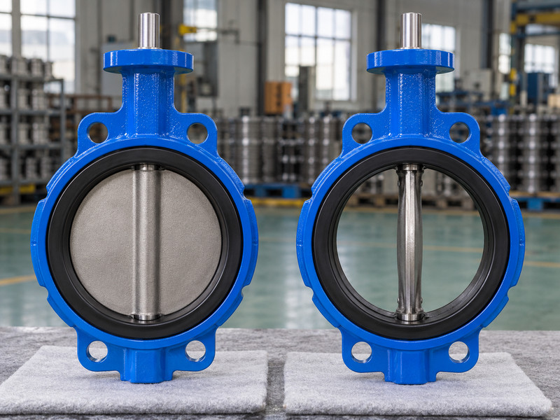
The disc in a double acting butterfly valve turns about its shaft, presenting different restrictions to flow as it moves. In a typical quarter-turn design, the open position places the disc approximately parallel with the flow direction. Closed-position sealing depends on the particular seat and disc design.
Can you infer flow from the position indicator?
A mechanical pointer indicates the drive’s position only when the coupling and indicator have been indexed correctly. It does not measure flow or prove seat tightness. At intermediate openings, the flow rate also depends on differential pressure and the installed system. Ask for configuration-specific flow data when calculating pressure loss or modulation.
- Verify indication against the disc before installation.
- Review the full disc envelope against mating bores.
- Use the valve’s actual flow data for a control calculation.
- During installation, confirm that adjacent flange bores, liners, and pipe fittings leave enough clearance for the disc’s full travel.
| Position | Typical geometry | Remaining check |
|---|---|---|
| Closed | Disc across the bore | Defined seat leakage test |
| Intermediate | Disc partly obstructs the bore | Flow duty and operating torque |
| Open | Disc approximately along the flow | Clearance and pressure loss |
Key takeaway: An “open” signal confirms a checked position, not a guaranteed flow rate.
3. How does a rack-and-pinion actuator turn the shaft?
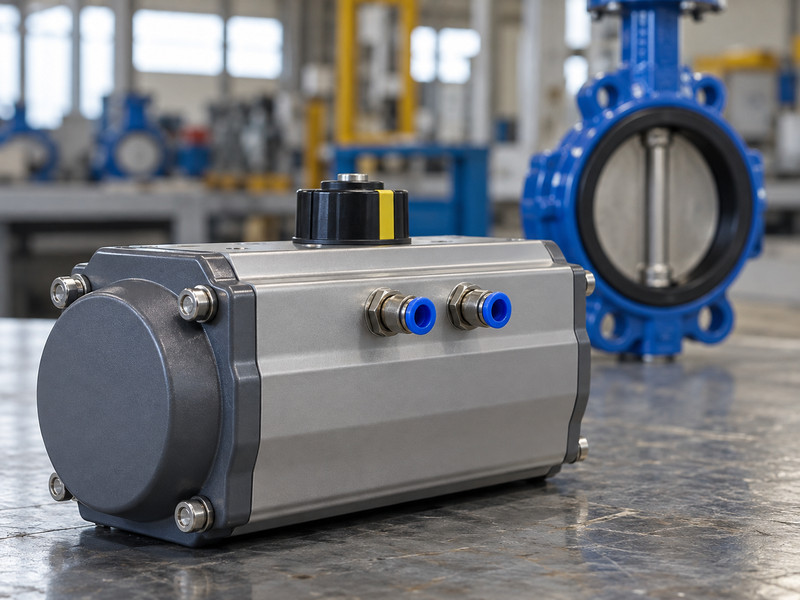
A rack-and-pinion drive in a double acting butterfly valve converts piston movement into shaft rotation. In a common opposed-piston arrangement, air moves two rack pistons relative to a central pinion. Reversing the air distribution reverses the output rotation; the detailed porting and assembly orientation depend on the actuator design.
What should you verify before connecting the drive?
Do not infer the opening direction from an actuator’s colour, exterior shape, or a photograph of another assembly. Confirm mounting orientation, output-drive fit, travel range, and stop adjustment procedure. The valve’s shaft and coupling must carry the selected torque without exceeding their limits. If maintenance requires internal actuator work, isolate and release stored energy using the applicable instructions; a spring-return actuator can contain mechanical energy even after its air supply is removed.
- Confirm rotation for each commanded air path.
- Review drive engagement and allowable torque.
- Keep the actuator’s assembly and maintenance instructions.
| Drive feature | What it determines | Verify with |
|---|---|---|
| Rack and pinion | Linear-to-rotary movement | Actuator documentation |
| Output interface | Connection to the valve shaft | Approved assembly drawing |
| Travel stops | Permitted movement limits | Setting and test procedure |
Key takeaway: Match the documented drive arrangement rather than relying on a generic actuator diagram.
4. Why are two pneumatic connections used?
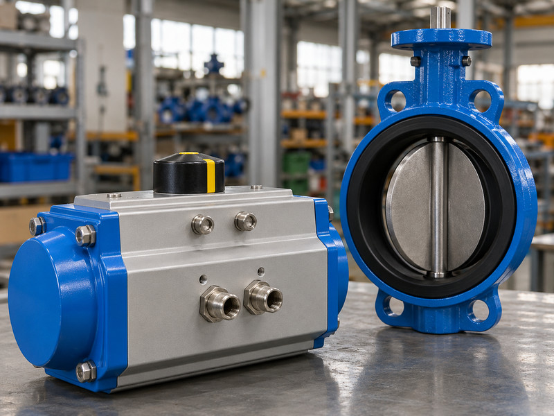
The two working pneumatic connections of a double acting butterfly valve allow the control system to pressurize one actuator circuit while exhausting the other. The arrangement supplies an opening stroke and a closing stroke. Both the supply and exhaust paths influence movement.
What limits the available air during a stroke?
A gauge upstream may show normal pressure while a small tube, restricted fitting, undersized solenoid, or clogged exhaust limits movement. Check dynamic pressure, directional-valve capacity, tubing length and bore, and the exhaust route together. Do not increase supply pressure beyond permitted limits to compensate for a restriction. For fast or frequent operation, review the site’s air capacity and required stroke time under representative conditions rather than assuming the assembly will repeat an unloaded bench result.
- Compare static and moving air-pressure conditions.
- Review tubing and directional-valve capacity together.
- Inspect exhaust restrictions before changing the actuator size.
| Air path | Possible restriction | Observable effect |
|---|---|---|
| Supply | Regulator, pipe, fitting | Pressure drops during motion |
| Working connection | Directional valve or tube | Delayed or uneven travel |
| Exhaust | Silencer or flow control | Slow movement despite supply pressure |
Key takeaway: Diagnose the complete pneumatic path before treating slow travel as a torque problem.
5. What happens if the air supply disappears?
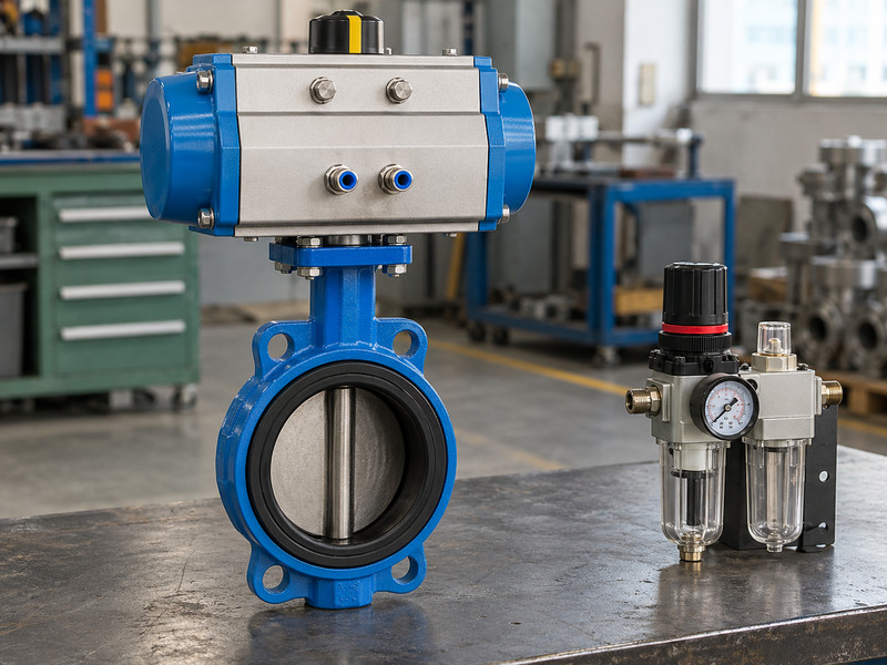
A standard double acting butterfly valve has no inherent spring-powered return stroke. Its position after air loss depends on the valve load, pneumatic circuit, leakage, and any engineered failure arrangement. Trapped air alone should not be treated as a guaranteed, indefinite position-holding system.
How should you define a failure requirement?
Loss of electrical power, loss of pneumatic supply, and a broken working tube can produce different conditions. State whether the process requires closure, opening, or a defined maintained state, then specify the response time and verification method. A spring-return package or an engineered stored-air arrangement may be appropriate, but each needs its own sizing and testing. A declared safety function also needs the project-specific system assessment; an actuator operating principle does not establish that qualification.
- Define air-loss, power-loss, and tube-failure events separately.
- State the required final state and response time.
- Test the selected arrangement under agreed representative conditions.
| Event | Question to resolve | Evidence |
|---|---|---|
| Air loss | Where can the disc move? | Assembly failure-response test |
| Power loss | Which pneumatic paths remain open? | Control function and test |
| Restart | Can motion occur unexpectedly? | Agreed restoration sequence |
Key takeaway: Write the failure response as an assembly requirement and verify it as an assembly behaviour.
6. Which seat material should you select?
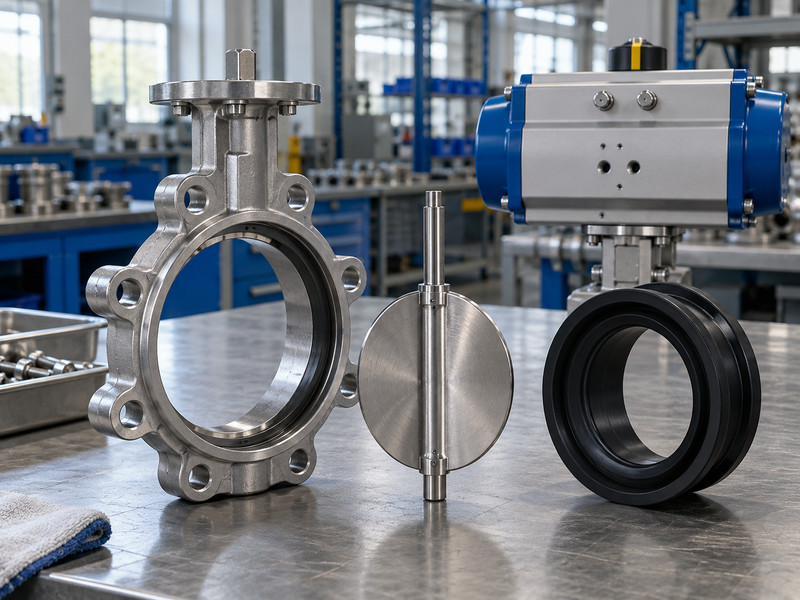
Select the seat of a double acting butterfly valve for the actual fluid and simultaneous operating conditions. Actuation type does not make an elastomer suitable for a chemical, oil, steam, or cleaning cycle. The seat compound and other wetted materials require their own review.
What information prevents a material mismatch?
Include concentration, additives, contaminants, solids, cleaning exposure, and the temperature range. For example, RUITO’s specified water-use and mineral-oil configurations use different seat selections and operating boundaries. Lined chemical-service valves also require review of the continuous lining, backing material, and shaft seals. If you compare PTFE-lined butterfly valves, ask for the exact configuration limits rather than transferring a resin’s general chemical reputation to the whole valve assembly.
- List process and cleaning fluids separately.
- Review temperature and pressure as a combined duty.
- Obtain written approval for seat-compound substitutions.
| Service information | Why it changes selection | Supplier response |
|---|---|---|
| Fluid composition | Changes material compatibility | Defined wetted-material list |
| Cleaning conditions | May exceed normal duty | Separate compatibility review |
| Solids and deposits | Affect sealing and torque | Stated operating limitations |
Key takeaway: Approve a complete material combination for a stated service rather than choosing a seat by name alone.
7. Does double acting identify the valve body style?
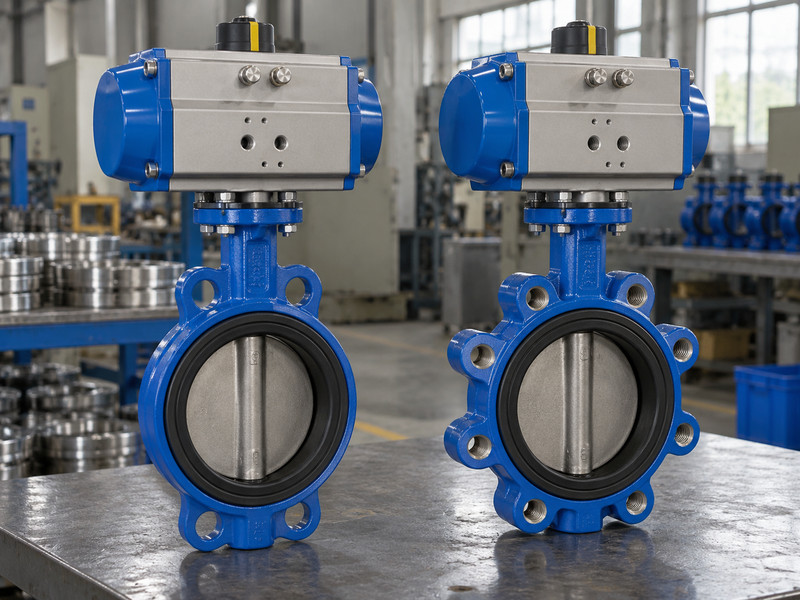
Double acting butterfly valve describes the actuator’s operation, while wafer, lug, and flanged describe connection arrangements. A double-acting actuator can be paired with different body designs when the interfaces, loads, and operating requirements are compatible. Offset geometry is another separate design choice.
Which connection details belong on your drawing?
Include face-to-face length, flange standard, pipe bore, fastener arrangement, actuator clearance, and any support requirement. A lug butterfly valve needs the specified bolt engagement and load assessment. Its end-of-line suitability must be declared for the actual configuration and duty rather than inferred from the presence of threaded lugs. For flanged designs, use the approved dimensions of that design; a wafer valve’s face length does not transfer to a double-flanged replacement.
- Confirm the precise body and connection arrangement.
- Review flange bore and disc clearance together.
- Treat end-of-line duty as a separate declared requirement.
| Description | What it identifies | What it leaves open |
|---|---|---|
| Wafer or lug | Connection arrangement | Material and failure response |
| Double acting | Pneumatic drive principle | Seat and offset geometry |
| Double offset | Disc and shaft geometry | Actuator operating principle |
Key takeaway: Keep connection style, offset geometry, and actuation type as separate selection fields.
8. How do you match the actuator to the valve?
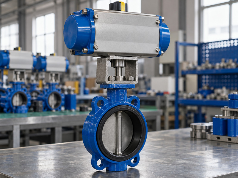
Match a double acting butterfly valve by checking valve torque against actuator output at minimum available air pressure, then checking the mechanical drive limits. Nominal bore and mounting-hole compatibility alone are insufficient. Both opening and closing requirements need review.
What should the sizing record contain?
Ask for the valve configuration, fluid, maximum differential pressure, temperature, required operating frequency, and applicable torque values. Document the sizing allowance and the actuator output used for both directions. Check the shaft, coupling, bracket, and stop limits against the maximum possible drive output. If the assembly later changes, review those inputs again.
- Use a configuration-specific valve torque basis.
- State minimum dynamic air pressure at the actuator.
- Check maximum drive output against mechanical limits.
- A replacement actuator using an ISO 5211 attachment reference may still have different output, air consumption, travel behaviour, or accessory interfaces.
| Review | Required comparison | Reason |
|---|---|---|
| Movement | Available versus required torque | Avoid stalling |
| Strength | Output versus drive limits | Avoid mechanical overload |
| Operation | Duty versus controls and air capacity | Achieve the required response |
Key takeaway: Preserve the sizing record so a future replacement can be assessed against the original duty.
9. How should you verify the complete operating sequence?
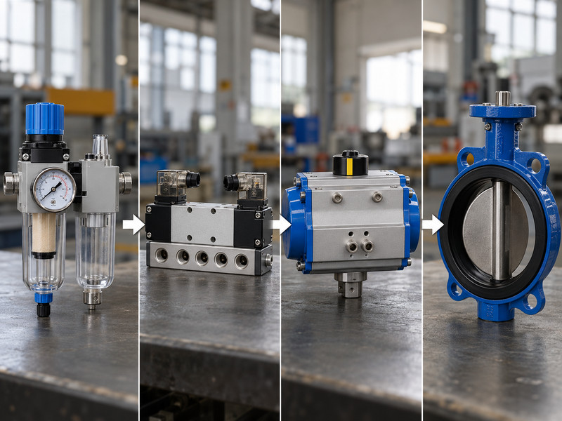
Verify a double acting butterfly valve through a defined sequence of mechanical, pneumatic, signal, and failure-response checks. Begin with isolation and safe access, then confirm the assembly configuration. Keep pressure-integrity testing and operating-sequence testing as separate acceptance items.
Which results should the handover record include?
Check commanded opening and closing, actual end positions, feedback signals, agreed stroke times, and the relevant supply conditions. If a requirement depends on process differential pressure, an unloaded cycle does not prove it. Test power loss, air loss, and restoration according to the approved design. Retain any limitations of the test arrangement so the site team knows which commissioning checks remain.
- Match each command with actual movement and feedback.
- Record supply conditions and any unloaded-test limitations.
- Agree which site checks remain before process operation.
- Finish by confirming access, identification, spare-parts information, and the applicable maintenance instructions.
| Stage | Record | Release condition |
|---|---|---|
| Assembly | Alignment and travel | Mechanical checks accepted |
| Function | Commands, signals, timing | Defined response demonstrated |
| Handover | Instructions and open actions | Site responsibilities assigned |
Key takeaway: Send RUITO your valve duty, minimum air supply, and required failure response when you contact us. We can review the assembly requirements before preparing a configuration-specific proposal.
10. What should you ask about daily operation?
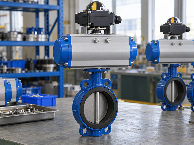
Use these questions when a double acting butterfly valve enters your equipment specification or maintenance plan.
- Q1: Can I use it for throttling? Sometimes. The valve, actuator, positioner or other controls, and process duty must support modulation. Check the permitted operating range and flow conditions for the selected assembly.
- Q2: How do I know if the valve is really closed? Verify the indication against actual disc travel, then use the specified closure test for leakage acceptance. A closed-position signal alone does not measure leakage.
- Q3: Can I reverse the two air tubes? Only under the documented control arrangement. Swapping tubes can reverse movement and affect the required de-energized state, indication, and restart sequence.
- Q4: What’s the best air pressure to specify? State both the permitted range and the minimum pressure available at the actuator during movement. The supplier must size and verify the package within those conditions.
- Q5: Can I replace a manual valve with a pneumatic package? Possibly. Review valve torque, shaft capacity, mounting, clearances, controls, and duty before conversion. A convenient mounting pad alone does not approve the modification.