
A butterfly valve bolt size chart must match the valve construction, mating flange standard and complete joint arrangement. Use a "butterfly valve bolt size chart" to identify a candidate fastener, then verify its thread, quantity and length on the approved drawing. Ordering from nominal size alone can leave an installer with bolts that align but cannot clamp the joint correctly.
1. What makes a butterfly valve bolt size chart usable?
A usable chart names the flange standard and class, valve body style, fastener type and assumptions behind its lengths. Those details determine whether a listed bolt or stud belongs in the proposed joint. Wafer, lug and double-flanged constructions retain the valve differently. A table copied without its heading can therefore provide a plausible thread size while giving the wrong length or quantity for the installation you actually have.
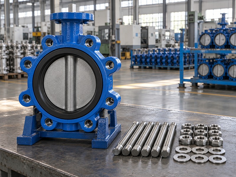
Which qualifiers should stay beside the table?
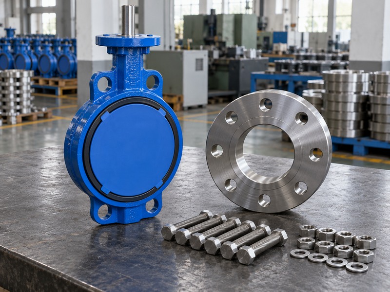
Keep the drawing revision, flange material, facing, washer arrangement and nut specification with the chart. Note whether the quantity means per flange, per side or per complete valve. A manufacturer may also use short blind fasteners near the neck where a long stud cannot pass. List those exceptions as separate positions in the fastener schedule. The small centering ears on a wafer body are locating features; their number does not establish the pipe flange's total bolt count.
- Identify through-bolt, stud or tapped-lug fastening.
- Retain all length and quantity assumptions.
- List neck-area exceptions separately.
| Chart field | What to identify | Risk if missing |
|---|---|---|
| Body construction | Wafer, lug or flanged | Wrong retention method |
| Connection designation | Standard, material and class | Wrong drilling pattern |
| Quantity basis | Per joint, side or assembly | Incomplete fastener set |
2. Which Class150 fastener sizes can you screen?
For common ASME B16.5 Class150 flange arrangements, the reference below gives familiar nominal fastener diameters and hole-position counts. It is a screening table, not a complete butterfly valve bolting specification. The actual valve can require different fastener forms at obstructed positions, and a lug valve needs its own tapped-thread confirmation. The table deliberately omits universal bolt lengths because those depend on the assembled joint and valve drawing.
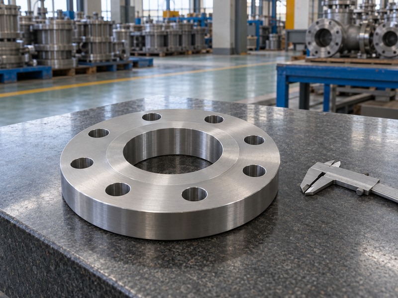
How should the reference table be applied?
Locate the exact pipe flange size and confirm the drilling against the supplier's accepted drawing. Treat the count as positions in one flange pattern, rather than a promise about the total bolts for a two-sided lug assembly. Confirm thread series, strength specification, coating and length separately. A metric fastener of a nearby diameter is not an approved substitute for the listed inch thread. If the valve is designed around EN flanges, use the appropriate EN connection schedule instead.
- Confirm Class150 and the applicable flange standard.
- Check the valve's own drilling and blocked positions.
- Do not use this table as a PN16 bolt schedule.
| NPS | Common inch thread | Flange hole positions |
|---|---|---|
| 2 | 5/8–11 UNC | 4 |
| 2½ | 5/8–11 UNC | 4 |
| 3 | 5/8–11 UNC | 4 |
| 4 | 5/8–11 UNC | 8 |
| 6 | 3/4–10 UNC | 8 |
| 8 | 3/4–10 UNC | 8 |
| 10 | 7/8–9 UNC | 12 |
| 12 | 7/8–9 UNC | 12 |
3. Why do wafer and lug valves need different fasteners?
A wafer valve is commonly retained between pipe flanges by fasteners that span the assembly, while a lug valve commonly receives separate fasteners from each side into threaded bosses. The load path and required engagement therefore differ. A through-stud schedule cannot be shortened by guesswork to create a lug-bolt schedule. Double-flanged valves introduce their own two flange joints and may require another arrangement around the neck or operator.
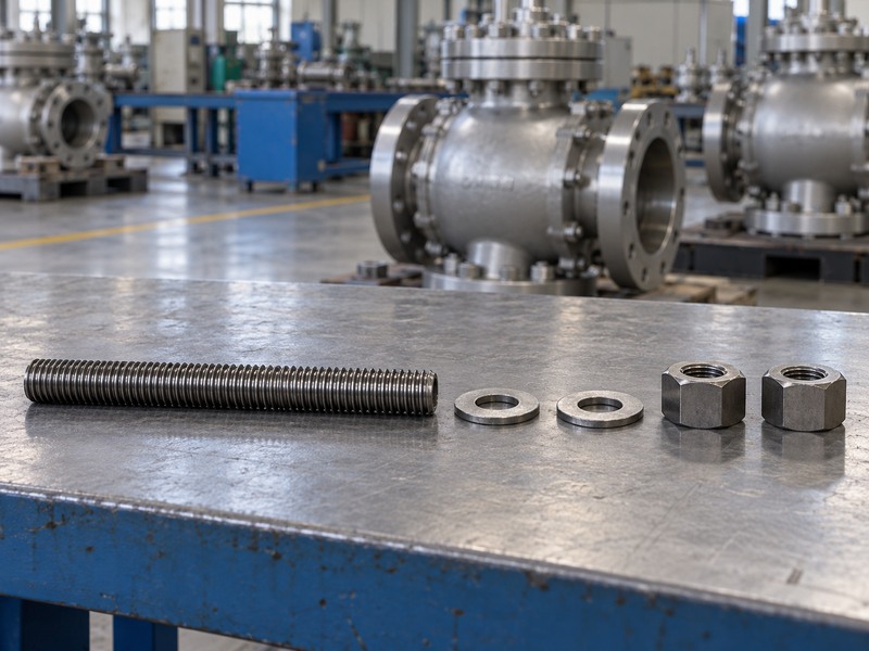
How do you count the complete assembly?
Start from the accepted joint drawing and count each fastener position, then identify its type and length. For a wafer butterfly valve, confirm which positions accept full through-studs and which need the manufacturer's special arrangement. For a lug body, list the two sides separately if flange thickness or engagement differs. Removing downstream piping also changes the load case; it requires an approved end-of-line configuration and isolation procedure, regardless of how many threaded bosses are visible.
- Draw the load path before counting components.
- Separate each side of a lug assembly.
- Keep end-of-line approval outside the ordinary bolt-count assumption.
| Construction | Common arrangement | Drawing check |
|---|---|---|
| Wafer | Fasteners span the valve and flanges | Through-path and neck clearance |
| Lug | Separate fasteners enter tapped bosses | Thread and engagement on each side |
| Double-flanged | Two separate flange joints | Facing, space and joint-specific bolting |
4. How do you calculate a wafer through-stud length?
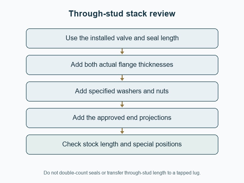
Calculate through-stud length from the complete axial stack between both stud ends. Include the installed valve sealing arrangement, two mating flange thicknesses, the specified washers and nuts, and the required projection. Add separate gasket thickness only where the approved arrangement requires it and it has not already been included. This method gives a reviewable starting length; the selected stock length must still satisfy the joint drawing and available space.
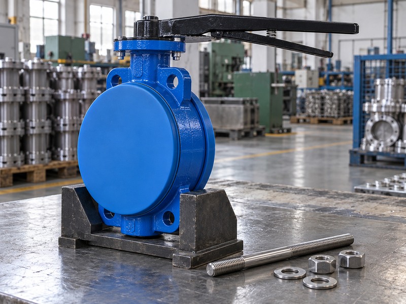
Which reference points belong in the calculation?
Write the stack as installed valve length plus both flange thicknesses, washers, nuts and end projections. For a headed through-bolt, use its under-head length convention and the correct single-nut arrangement instead of copying a two-nut stud total. Check thread coverage across the loaded nut engagement and any unthreaded shank near the joint. Do not round a calculated length before checking whether the next stock size strikes the neck, nearby pipework or a maintenance obstruction.
- Use installed dimensions and the approved seal stack.
- Distinguish overall stud length from under-head bolt length.
- Check stock-length rounding against clearance and thread coverage.
| Stack term | Include when applicable | Avoid |
|---|---|---|
| Valve and seals | Approved installed arrangement | Counting the same gasket twice |
| Flanges and washers | Actual specified thicknesses | Unstated catalogue assumptions |
| Nuts and projections | Accepted fastener detail | Universal projection or length rules |
5. How do thread diameter and pitch affect selection?
Both diameter and pitch must match the required thread specification. A bolt that appears close in diameter can damage a tapped lug after a few turns if its pitch differs. Inch threads are commonly described by diameter, threads per inch and series; metric threads identify nominal diameter and pitch in millimetres. The clearance hole in a mating flange does not identify the thread required inside the valve's lug or mounting component.
What should you inspect on an existing fastener?
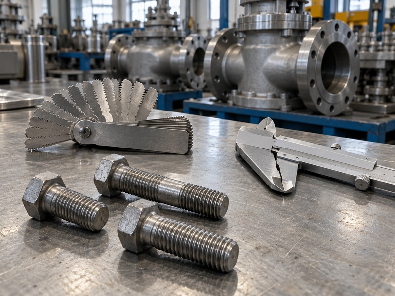
Measure diameter with a suitable instrument and verify pitch with a thread gauge, then compare the result with the controlled specification. Inspect damage, corrosion and coating buildup that could distort the reading. A used bolt is supporting evidence rather than proof that the original installation was correct. For a lug butterfly valve, obtain the specified thread and usable engagement from the valve drawing before buying replacements or attempting to retap a damaged boss.
- Record complete thread designations.
- Verify diameter and pitch independently.
- Do not force a reluctant bolt to test whether it fits.
| Thread detail | How to confirm | What it establishes |
|---|---|---|
| Nominal diameter | Drawing and diameter check | Basic fastener size |
| Pitch or TPI | Thread gauge and specification | Mating thread compatibility |
| Series and fit | Controlled thread callout | Required thread form and tolerance |
6. Why can a chart show more than one length per valve?
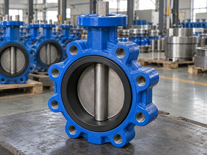
A chart can show several lengths because fastener access and engagement vary around the valve. The neck, gearbox, body ribs or special mounting bosses can block a full through-path at selected positions. Lug threads may also be machined from opposite sides without a continuously usable threaded passage. One long bolt pushed through such a location can bottom out, damage the valve or interfere with the opposite fastener.
How should exceptions be scheduled?
Use a position sketch that identifies the exceptional holes and their specified fasteners. Count short bolts, studs, nuts and washers by type rather than ordering one bulk length for the whole circumference. Check the assembly sequence as well: a technically correct bolt can become inaccessible after the actuator is mounted. If the supplier changes operator orientation or body revision, recheck the exceptions. A fastener schedule should describe the actual assembly that reaches the site, including any installation access limits.
- Identify blocked and blind positions on a sketch.
- Confirm opposite-side fastener clearance.
- Recheck access after operator orientation changes.
| Exception | Reason for a separate item | Required evidence |
|---|---|---|
| Neck obstruction | Through-stud cannot pass | Position-specific drawing |
| Blind tapped boss | Length limited by usable depth | Engagement and bottom clearance |
| Restricted tool access | Head or nut cannot be reached | Assembly and maintenance access review |
7. Does the correct size establish fastener strength?
Correct diameter and length establish only part of the fastener specification. Material, strength grade, temperature suitability, coating and the joint's required preload still need review. A stainless bolt is not automatically equivalent to a specified alloy-steel stud, and a higher strength marking does not authorize a higher flange tightening torque. The flange, valve body, seat and gasket can impose limits before the bolt reaches its own strength limit.
What should the purchase description contain?
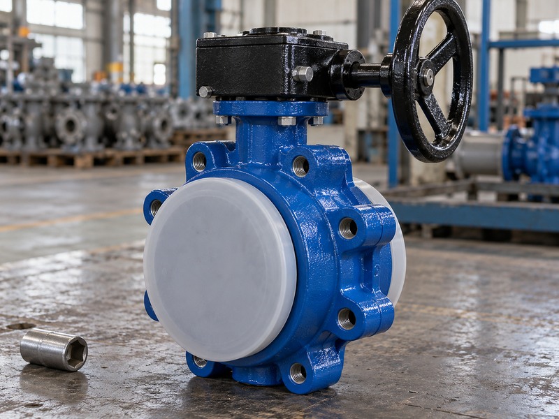
List the complete bolt or stud specification, matching nuts and washers, coating condition and required material evidence. Include lubrication assumptions in the installation procedure because friction changes the relationship between applied torque and achieved tension. For a flanged butterfly valve, confirm the mating flange's limitations alongside the valve instructions. Keep substitutions under the same engineering review as other pressure-boundary components; changing a coating or nut type can change how the joint behaves during tightening.
- Specify fastener, nut and washer materials together.
- Keep grade and tightening limits separate.
- Record coating and lubrication assumptions.
| Specification item | Question to close | Insufficient shortcut |
|---|---|---|
| Material and grade | Suitable for the joint and temperature? | Diameter alone |
| Nuts and washers | Matched to the required assembly? | Whatever fits the thread |
| Surface condition | Compatible with the tightening procedure? | A generic dry-torque table |
8. Can a bolt size chart provide the tightening torque?
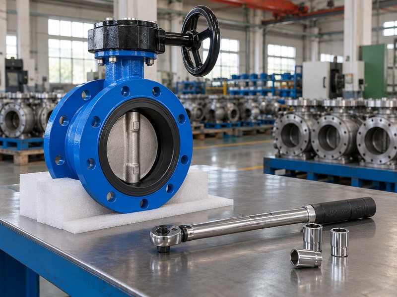
A size chart can provide tightening torque only when the stated procedure and assumptions apply to the exact joint. Diameter alone cannot determine an installation torque. Friction, lubrication, fastener grade, gasket behavior, flange material and the valve's sealing construction all affect the approved value. Use the applicable assembly procedure and the valve manufacturer's limits; do not transfer a figure from another supplier's chart because the nominal size happens to match.
What should the installer check before tightening?
Confirm alignment, the specified sealing arrangement, correct fastener engagement and unobstructed disc travel under the approved isolated procedure. Follow the required tightening sequence and staged passes with suitable tools. A bolt that reaches its stated torque after bottoming in a lug has not necessarily clamped the flange. If leakage appears later, investigate alignment, seal condition and load distribution before applying more force. Excess tightening can damage a resilient seat or a weak mating flange without correcting the original cause.
- Use the approved joint-specific torque procedure.
- Check engagement and bottom clearance before tightening.
- Investigate leakage before increasing load.
| Installation check | Purpose | Possible fault |
|---|---|---|
| Alignment and seals | Establish a suitable joint | Uneven contact |
| Fastener seating | Confirm real clamping | Bottomed bolt or damaged thread |
| Staged tightening | Distribute load as specified | Distortion or uneven compression |
9. How do you approve the final fastener schedule?
Approve the schedule by matching every fastener position to the accepted valve and pipe joint drawing. Include quantity, diameter, pitch, type, length, grade, nuts, washers and any special location notes. Separate the screening table from the installation bill of materials so its limited assumptions remain visible. A complete schedule lets procurement order the right set and lets the installer verify what arrived before the valve enters the line.

What should you send with a technical enquiry?
For RUITO enquiries, contact us with the valve body style, nominal size, mating flange standard, flange thickness and required sealing arrangement. Add the existing fastener survey and photographs when replacing an installed unit. Ask the supplier to confirm all exceptions near the neck and operator, then retain that response with the purchase order. Check the delivered fastener set against the approved schedule and resolve substitutions before installation begins.
- List each distinct fastener type and location.
- Match the schedule to the accepted drawing revision.
- Inspect delivered quantities and markings before assembly.
| Review stage | Evidence | Release condition |
|---|---|---|
| Screening | Correct standard and body style | Suitable starting schedule |
| Engineering | Complete stack and position drawing | Lengths and engagement accepted |
| Delivery | Fastener identification and quantity | Matches the approved bill of materials |
10. What questions arise when choosing butterfly valve bolts?
Q1. Can I use the same bolts for wafer and lug valves?
Only if the exact joint drawings specify the same fastener. Wafer through-bolting and lug engagement normally use different load paths and lengths. Confirm thread, quantity, engagement and access for the actual construction.
Q2. How do I know if a bolt is too long for a lug?
Compare its projection beyond the flange and washer with the usable tapped depth and required clearance. A bolt can bottom before the flange is clamped. Opposite-side fasteners and thread runout also reduce available space.
Q3. Can I replace an inch bolt with a similar metric size?
Do not substitute by diameter alone. Pitch, thread form, fit, strength and joint geometry must match the approved specification. Obtain an engineering-approved change if a different fastener system is proposed.
Q4. What's the best torque for a given bolt diameter?
Use the approved joint-specific value and procedure. Diameter alone leaves friction, material, grade, gasket and flange limits unresolved. A general fastener torque chart may exceed the valve or mating flange's allowed load.
Q5. Can I count the wafer valve's ears to order the bolt set?
No. Centering ears do not establish the full flange bolt pattern. Count the accepted mating-flange positions and identify any special fasteners at neck or blind locations on the valve drawing.