
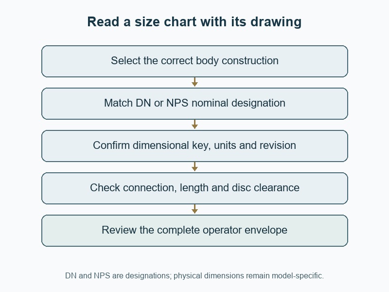
A butterfly valve size chart is useful when it identifies both nominal size and the exact valve configuration behind each dimension. Use a "butterfly valve size chart" to screen options, then confirm the selected model's drawing. A generic table can match the pipe designation while leaving you with the wrong body length, bolt pattern or operating clearance.
1. What should a butterfly valve size chart identify?
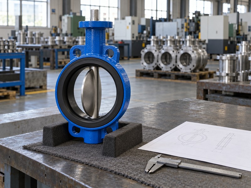
A usable chart should identify the manufacturer, valve construction, nominal size, connection standard and drawing revision. Those fields tell you which physical assembly the numbers describe. A table headed only 'butterfly valve dimensions' can combine measurements from unrelated designs or leave the measurement reference unclear. Before comparing suppliers, establish whether the chart covers a wafer, lug, double-flanged or grooved body and which pressure designation applies to the listed connection.
Which table labels prevent ordering mistakes?
Ask for an illustrated dimensional key beside the table. Letters such as A, B and C have no universal meaning across valve catalogues; one supplier may use A for overall height while another uses it for body length. Confirm whether height includes the bare stem, gearbox or complete actuator package. Keep the drawing and its table together during review so a copied spreadsheet row cannot lose the qualifiers that make its dimensions meaningful.
- Keep the dimensional sketch and chart revision together.
- Identify the supplied operator separately from the bare body.
- Record units in every dimensional column.
| Chart field | Required context | Decision supported |
|---|---|---|
| Nominal size | DN or NPS designation | Initial size screening |
| Construction | Body and connection type | Correct drawing family |
| Dimension key | Reference faces and units | Reproducible comparison |
2. How do DN and NPS correspond in a size table?
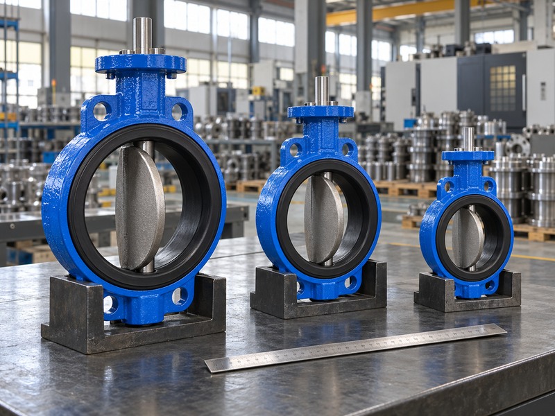
DN and NPS provide corresponding nominal size designations for many common pipework sizes. The table below lists familiar pairings for screening industrial butterfly valves; it does not give measured bores or flange dimensions. For example, DN150 commonly corresponds to NPS6, but multiplying six inches by 25.4 does not turn DN150 into a promise about the finished opening. Confirm the designation and connection standard before comparing physical measurements.
How should you use the nominal-size reference?
Start with the pipework designation on the equipment schedule, then locate the same nominal entry in the correct product chart. ISO 6708 addresses DN designation, while the selected pipe and component standards define the dimensions that you must match. Do not change a specified size because a nearby measured opening appears closer to another nominal number. A liner, thick pipe wall or disc profile can explain the apparent difference without changing the nominal designation.
- Use this table for designation comparison only.
- Check dimensions in the model-specific drawing.
- Keep the specified flange standard attached to the size.
| DN designation | Corresponding NPS | What it identifies |
|---|---|---|
| DN50 | NPS2 | Nominal size |
| DN65 | NPS2½ | Nominal size |
| DN80 | NPS3 | Nominal size |
| DN100 | NPS4 | Nominal size |
| DN125 | NPS5 | Nominal size |
| DN150 | NPS6 | Nominal size |
| DN200 | NPS8 | Nominal size |
| DN250 | NPS10 | Nominal size |
| DN300 | NPS12 | Nominal size |
3. Why do equal nominal sizes have different body lengths?
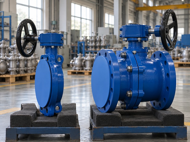
Equal nominal sizes can have different lengths because their body constructions, connection forms and dimensional series differ. A wafer valve fits between pipe flanges, while a double-flanged valve carries its own end flanges. Their installed lengths and fastening arrangements follow different drawings. Even within one body type, material, seat design or a separate dimensional series may change the required space. A nominal-size conversion table cannot establish installation interchangeability.
Which length belongs in your comparison?
Compare the specified face-to-face or end-to-end dimension under the drawing's stated reference conditions. Note whether a resilient face projects beyond the casting and whether the installation dimension accounts for compression or separate gaskets. For a wafer butterfly valve, also check how the surrounding flange gap is defined. If a replacement changes body length, review the pipework change before ordering; pulling the flanges together with bolts can transfer unwanted loads into the assembly.
- Compare the same dimensional references.
- Identify gasket and resilient-facing conditions.
- Review pipework changes before accepting another length.
| Body style | Length reference to confirm | Separate check |
|---|---|---|
| Wafer | Specified face-to-face | Seat projection and installation condition |
| Lug | Specified face-to-face | Lug threads and bolt length |
| Double-flanged | Drawing-defined end faces | Flange standard and facing |
4. Can one chart cover every flange standard and class?
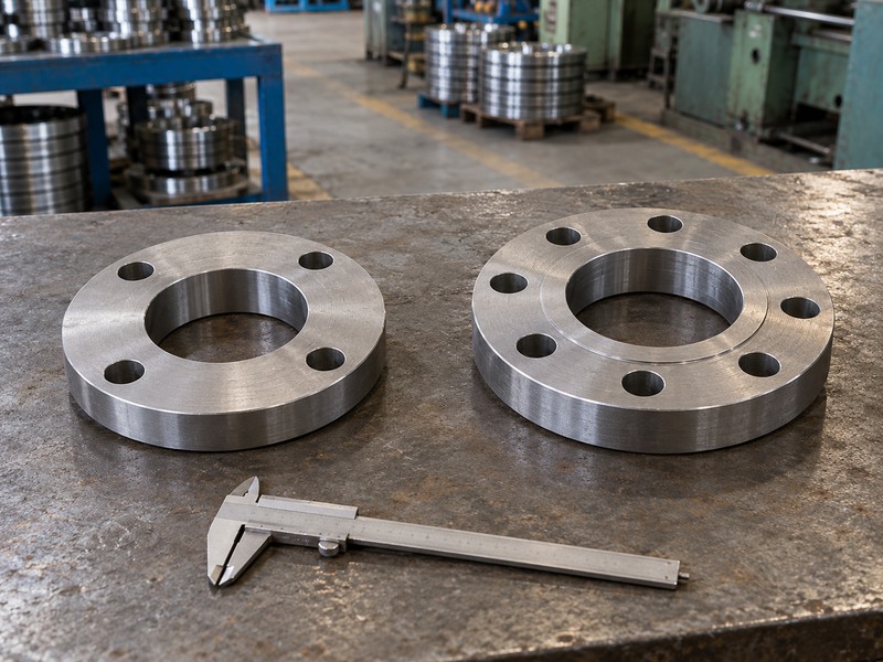
One chart can cover multiple connections only when it identifies each configuration and its limitations clearly. EN PN16, ASME Class150 and other flange systems are not interchangeable labels. Hole count, bolt circle, fastener size, facing and flange thickness can differ. A body advertised for more than one drilling pattern still needs the supplier's confirmation for the exact mating flange, especially where a large hole or slotted feature accommodates more than one pattern.
What should you compare before accepting multi-drilling?
Review both sides of the proposed joint, including the pipe flange material and its internal bore. A drilling match cannot prove suitable sealing contact or disc clearance. Keep pressure-temperature suitability separate from the mechanical pattern: an assembly with matching holes may still exceed the seat's shutoff limit or another component's rating. Ask the supplier to mark the accepted flange designation on the quotation and drawing rather than relying on a broad catalogue statement about international compatibility.
- List the exact standard and pressure designation.
- Check facing and bore alongside drilling.
- Confirm any multi-standard compatibility in writing.
| Comparison | Why it is separate | Record needed |
|---|---|---|
| Drilling | Determines hole alignment | Pattern dimensions |
| Sealing face | Determines supported contact area | Joint detail |
| Service rating | Limits pressure and temperature | Configuration-specific rating |
5. Which dimensions check the disc's operating envelope?
Check the disc's swept envelope, its projection beyond each valve face and the minimum bore through adjacent components. A valve can fit inside the available flange gap while its opening disc strikes a pipe liner or reducer. The chart's overall height and body length do not describe this moving envelope. Ask for a clearance drawing or the exact model's installation limits whenever the valve sits close to another fitting or piece of equipment.
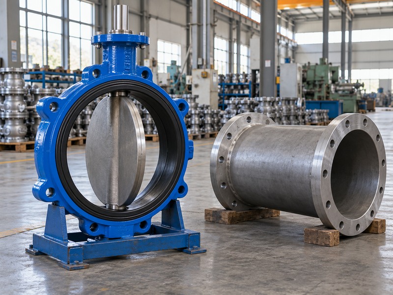
How do nearby components change the review?
Record the internal profile and distance of each potential obstruction from the valve reference face. A reducer begins changing diameter along the pipe axis, so its smallest diameter alone does not describe whether it intersects the moving disc. An adjacent check valve may introduce another moving part. Confirm the combined arrangement rather than treating each catalogue item as independently clear. If the clearance remains unverified, keep it open on the installation review instead of assuming that equal DN values settle the question.
- Check both sides of the valve.
- Include linings, reducers and neighbouring moving parts.
- Use the complete travel envelope, not a single static diameter.
| Listed dimension | What it helps establish | What remains unresolved |
|---|---|---|
| Body length | Required axial space | Open-disc projection |
| Disc envelope | Moving-part clearance | Actual pipe profile |
| Pipe bore and spacing | Available passage | Combined movement of nearby equipment |
6. How do operator dimensions change the required space?
Operator dimensions add height, width, weight and access needs to the bare valve envelope. A lever needs sweep space, a handwheel needs operating access and an electric actuator needs room for its cover and service connections. The same valve body can therefore occupy several different installation envelopes. A chart that lists only body dimensions cannot confirm whether the complete actuated package will fit inside a skid, pit or equipment enclosure.
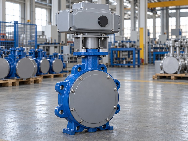
Which drawing should the installer receive?
Use an assembly drawing showing the selected bracket, coupling and operator in the agreed orientation. Include cable-entry clearance, pneumatic tubing access and the space required to remove covers. A top-mounting pattern confirms part of the interface; it does not establish torque suitability or shaft engagement. When comparing a lug butterfly valve package with another supplier's unit, check the complete assembly height and service access rather than accepting a shorter bare-body dimension as a direct saving.
- Request dimensions for the complete supplied assembly.
- Check operating sweep and cover-removal space.
- Review mounting geometry and torque separately.
| Operator | Space to reserve | Additional information |
|---|---|---|
| Lever | Full handle sweep | Locking and access |
| Gearbox | Handwheel and service access | Orientation and manual effort |
| Actuator | Housing, connections and cover access | Weight, support and coupling |
7. Does a larger listed size guarantee more usable flow?
A larger nominal size usually changes the available flow area, but usable capacity must come from the selected valve's flow data and operating conditions. Disc shape, shaft obstruction and opening angle affect the flow coefficient. Comparing outside dimensions cannot establish a pressure drop or a controllable operating range. For isolation, review the required flow at the allowed loss; for modulation, examine the minimum, normal and maximum operating cases across the proposed travel range.
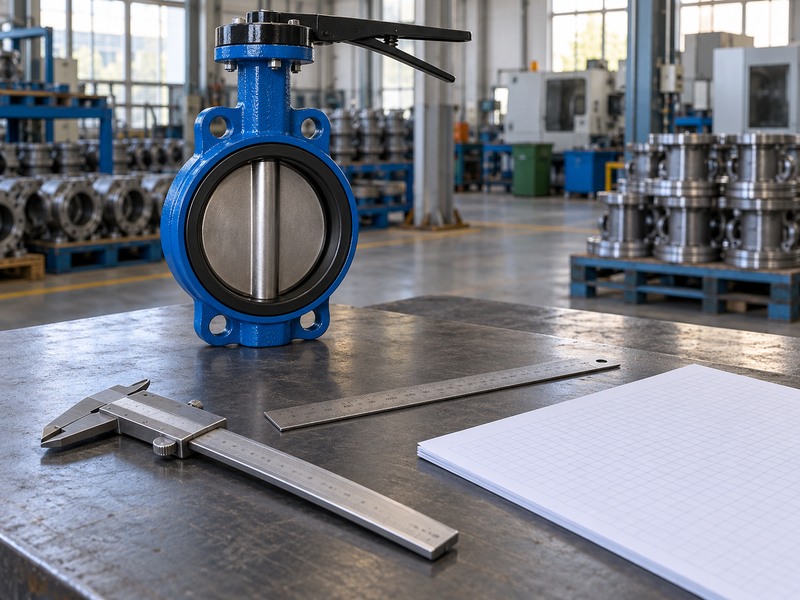
What data should accompany a hydraulic comparison?
Request the model-specific Cv or Kv information with its units, test basis and opening reference. Supply the actual fluid, density, viscosity, temperature and available pressure difference. Avoid using one full-open coefficient for every size or assuming that a positioner makes the whole travel range suitable for throttling. The physical size chart remains useful for layout, while the hydraulic calculation determines whether the chosen configuration can meet the process requirement without unacceptable noise, cavitation or loss of control.
- Use the coefficient for the exact valve and opening.
- State fluid properties and pressure conditions.
- Keep isolation capacity and modulation performance distinct.
| Selection question | Relevant data | Insufficient substitute |
|---|---|---|
| Will it fit? | Dimensioned assembly drawing | Nominal size alone |
| Will it pass the flow? | Cv/Kv and operating case | Body outside diameter |
| Will it control? | Installed characteristic and travel range | Full-open capacity alone |
8. How should RUITO size ranges appear in your shortlist?
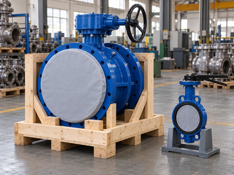
RUITO size ranges should appear as construction-specific availability, followed by confirmation of the exact configuration. The project training data lists water-service wafer and concentric double-flanged butterfly valves at DN50–600, lug valves at DN50–300 and U-type valves at DN150–600. These ranges identify starting options; they do not make the body lengths, materials, ratings or installation details identical across the range. Confirm availability and requirements for the proposed order.
Which other constructions need separate rows?
Double-offset double-flanged, grooved and lined constructions have their own stated ranges and application limits. For example, the supplied business data lists double-offset double-flanged valves at DN350–3000, while PTFE-lined and PFA-lined valves have smaller, separate ranges. A flanged butterfly valve enquiry should identify whether concentric or double-offset construction is required. Use the supplier's current configuration response to close the shortlist, rather than merging all catalogue endpoints into a single product capability claim.
- Keep connection and sealing construction visible.
- Confirm current supply for the exact size and service.
- Do not combine maximum size, temperature and pressure from different configurations.
| RUITO construction | Stated nominal range | Confirm separately |
|---|---|---|
| Water-service wafer / concentric double-flanged | DN50–600 | Materials, rating and interface |
| Lug / U-type | DN50–300 / DN150–600 | Connection-specific dimensions |
| Double-offset double-flanged | DN350–3000 | Direction, torque and installation envelope |
9. How do you turn a size chart into an approved order?
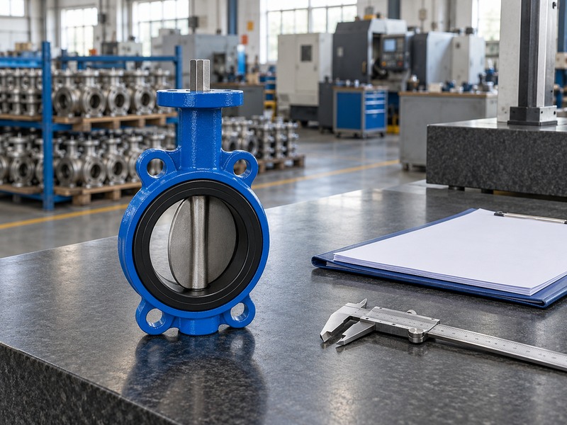
Turn the chart entry into an approved order by linking it to the selected configuration, drawing revision and service requirements. Record every dimension that controls installation, including body length, drilling, disc clearance and operator envelope. A spreadsheet comparison can identify a suitable candidate, but a supplier must still confirm the item being offered. Keep any deviation from the existing installation visible until the responsible engineer accepts the required change.
What should the supplier confirm in its response?
Ask for a marked drawing and a clear list of included components, particularly gaskets, fasteners, brackets and operators. For RUITO enquiries, contact us with the pipe designation, mating flange details, available space and operating conditions so the proposed assembly can be reviewed. Retain the accepted chart and drawing with the purchase order. If the supplier changes the body, seat or actuator revision, compare the new dimensions and loads before releasing production or accepting a replacement.
- Link the chart row to an exact configuration.
- Close dimensional and service deviations together.
- Control drawing changes after approval.
| Order evidence | Required link | Acceptance decision |
|---|---|---|
| Size chart | Exact product and revision | Correct candidate selected |
| Assembly drawing | Field dimensions and components | Installation fit accepted |
| Service data | Same material and drive configuration | Operating limits accepted |
10. What questions arise when reading butterfly valve charts?
Q1. Can I use a universal butterfly valve size chart?
Use it for preliminary comparison only. A chart without an identified construction, connection standard and dimensional key cannot establish replacement fit. Obtain the exact model drawing before ordering.
Q2. How do I know whether DN150 matches NPS6?
They are commonly corresponding nominal designations. Check the component standard and supplied configuration, then compare actual interface dimensions. The nominal pairing does not establish a measured 150 mm or six-inch bore.
Q3. Can the same DN valve use a different face length?
Yes. Body styles and dimensional series can differ at the same nominal size. Compare the specified reference faces, sealing arrangement and installed condition before assuming interchangeability.
Q4. What's the best chart for an actuated replacement?
Use the complete assembly drawing and its dimensional table. Include the chosen actuator, mounting hardware, cable or air connections and maintenance access. A bare-body table leaves those installation requirements unresolved.
Q5. Can I choose a larger valve to avoid pressure loss?
Only after a hydraulic review. A larger valve changes capacity and may reduce useful control travel during modulation. Check actual flow cases, pressure difference and the model's Cv or Kv data before changing size.