
Fix reading mistakes in a butterfly valve diagram by identifying the view type and matching its callouts with the actual valve family. Trace the disc, seat, stem, supports and seals through the relevant assembled view. Keep schematic relationships and separated parts distinct from controlled dimensions, physical condition and accepted test results.
An exploded view can separate a seat and body that meet in the assembled valve. A section may omit a support outside its cutting plane. Read those presentation choices before treating a missing line, gap or displayed disc position as a defect or installation instruction.
1. What kind of butterfly valve diagram is this?
Identify the type of butterfly valve diagram through its title, view references and legend before interpreting internal details. A section shows relationships through a stated cut, while an exploded view separates components for identification. A general arrangement or functional schematic serves another purpose and may leave those internal relationships undefined.
Which question can each drawing type answer?
Read the view description. Use sections for defined internal relationships and exploded views for component identity. General arrangements provide their stated installation information, while schematic functions follow the legend. Follow the supporting reference when one view cannot answer the review question.
- Identify section, exploded, general-arrangement or schematic scope.
- Read the view references and applicable legend.
- Follow supporting views for details outside that scope.
Key takeaway: Match the question with the drawing type before interpreting what a line or gap represents.
| Check | What you should confirm |
|---|---|
| Section | Defined cut reveals particular internal relationships |
| Exploded view | Separated components support identification and callouts |
| Other views | Arrangement or schematic meaning follows its stated purpose |
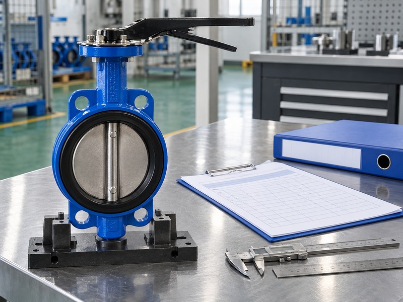
2. Which family fits a butterfly valve diagram?
A butterfly valve diagram must match the actual model, body style and internal construction before its callouts can identify the supplied parts. Record the document and applicable variant beside the valve identity. Similar component names do not make figures from different families interchangeable.
What connects a callout with the correct component?
Match the figure and parts list. The Bray resilient-seat manual provides construction-specific appendices with different component arrangements. Follow callouts into their own parts list and retain variant notes. Another appendix’s item label cannot establish the component, material or location in the selected valve.
- Identify the actual model and applicable drawing variant.
- Read callouts against their own figure and parts list.
- Retain notes that change component coverage or construction.
Key takeaway: Interpret callouts within their own model and figure rather than transferring labels between families.
| Check | What you should confirm |
|---|---|
| Family | Drawing identifies the actual construction being reviewed |
| Callout | Leader connects with a defined item in that figure |
| Parts list | Description and applicable notes match the selected variant |
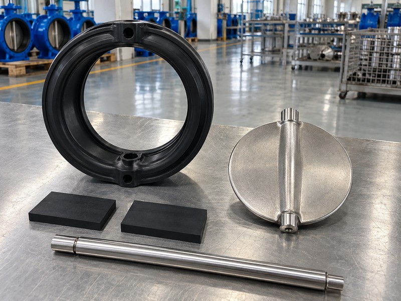
3. How do you read a butterfly valve diagram section?
Read a butterfly valve diagram section through its stated cutting plane, viewing direction and assembled relationships. Locate the disc, stationary seat region and stem before following smaller features. A component outside the chosen cut may appear in another view or remain represented only by its callout and parts record.
What should the inside-view reading establish?
Trace the assembled relationships. Follow the disc-to-stem connection, sealing region and shaft passage through the body. Check view references and legend before interpreting hatching, omitted lines or simplified features. A drawing cut cannot establish that a photographed valve was physically sectioned, damaged or opened for inspection.
- Locate the cutting plane and viewing reference.
- Trace disc, seat and stem through the assembled view.
- Use companion views for features outside the section.
Key takeaway: Read the section as a defined view of the construction rather than a complete inventory of every visible line.
| Check | What you should confirm |
|---|---|
| Cut | Selected plane defines the internal features being shown |
| Relationships | Disc, seat and stem connections match the assembled view |
| Coverage | Companion references identify features omitted from the cut |
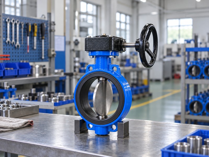
4. What does an exploded butterfly valve diagram show?
An exploded butterfly valve diagram shows components separated to clarify identity and assembly relationships. The displayed spacing does not define operating clearance, actual gaps or service position. A sequence of separated parts also cannot authorize a removal order or a maintenance procedure.
How should separated parts be mapped back to the assembly?
Return to the assembled view. Match each component with its callout, orientation notes and corresponding location in the actual section. Read retention and contact relationships in that assembled condition rather than measuring exploded spacing. Physical access or component removal belongs to the selected instructions and an authorized work process, including applicable isolation and energy controls.
- Use exploded spacing for identification rather than clearance.
- Match orientation and location through the actual assembled view.
- Keep physical maintenance within selected authorized procedures.
Key takeaway: Use exploded views to identify components and assembled views to understand their actual relationships.
| Check | What you should confirm |
|---|---|
| Separation | Spacing clarifies components without supplying an operating gap |
| Assembly | Companion view defines actual contact and retention relationships |
| Work scope | Selected instructions govern any authorized physical procedure |
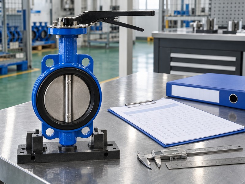
5. What supports appear in a butterfly valve diagram?
The supports appearing in a butterfly valve diagram depend on its actual shaft, disc and body construction. Bearings or bushings support the designed movement, while seals address their specified leakage paths. Their proximity around a shaft does not make their functions or component identities interchangeable.
How should stem, support and seal callouts be separated?
Read each part’s defined function. Emerson’s isolation-valve portfolio identifies a one-piece disc-stem for its Keystone Figure 990/920 example. Other families use different arrangements. Confirm shaft pieces, any packing gland and bearing count through the actual parts record rather than a generic diagram.
- Identify the actual disc-stem connection or integrated arrangement.
- Separate movement support from the specified sealing function.
- Read component presence and count through the selected parts record.
Key takeaway: Use the selected construction to interpret support and sealing functions without inventing a universal internal layout.
| Check | What you should confirm |
|---|---|
| Stem | Selected drawing defines the actual drive relationship |
| Support | Bearing or bushing duties follow the identified construction |
| Seal | Stem-sealing features have their own model-specific definition |
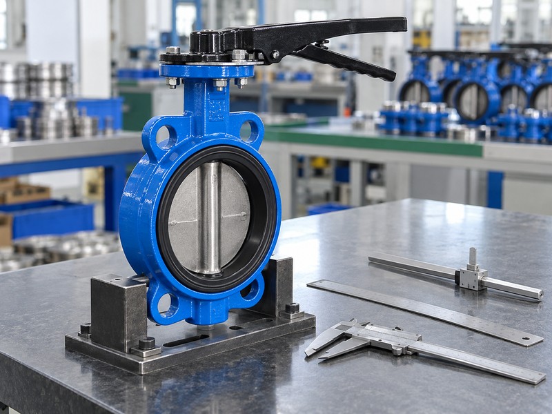
6. What joints appear in a butterfly valve diagram?
The joints and retainers in a butterfly valve diagram must be identified through the actual construction. A split-body joint, pipe-flange interface, seat retainer and stem-sealing region can serve different functions. A line near the seat cannot establish which interface it represents without its callout and assembled detail.
Why should sealing interfaces stay separately identified?
Trace each sealing boundary. The Bray McCannalok manual identifies a retained seat for its named high-performance construction. Match actual body joints, seat retention and flange seals with selected details. Seat, external stem and body or flange leakage need separate observations and verification, with corrective work governed by the actual instructions.
- Identify body joints and retention through actual callouts.
- Separate seat, stem and pipe-interface sealing functions.
- Use selected construction details for gasket and retention requirements.
Key takeaway: Map each joint and seal to its actual function before assigning a leakage or service interpretation.
| Check | What you should confirm |
|---|---|
| Body | Joint or one-piece construction follows the actual design |
| Seat retention | Selected detail defines applicable retaining features |
| Leakage path | Each sealing boundary has its own observation and acceptance basis |
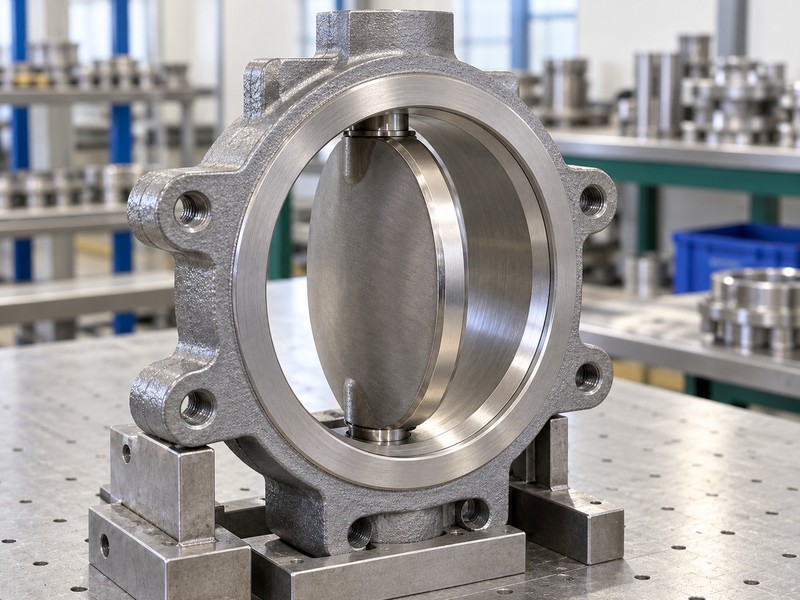
7. What do butterfly valve diagram arrows mean?
Arrows in a butterfly valve diagram mean what the selected legend and notes define. Distinguish viewing or section references, indicated flow, preferred pressure direction and operator rotation. A displayed disc position or one flow arrow cannot establish every permitted operating direction or endpoint.
How should flow-path marks be read without overclaiming?
Identify the arrow’s reference. Read its function and observer direction, then check applicable operating instructions. The conceptual chart concerns pressure loss versus flow at constant opening, flow coefficient and liquid density, with no leakage curve or measured model data. Disc and shaft can still obstruct an open-position sketch; it cannot establish an empty pipe or zero pressure loss.
- Read arrow meaning through the actual legend and notes.
- Separate displayed position from permitted movement and duty.
- Use actual model data for flow or directional-performance claims.
Key takeaway: Read arrows and displayed positions within their defined scope instead of treating them as universal instructions.
| Check | What you should confirm |
|---|---|
| Reference | Arrow has an identified view, flow, pressure or rotation meaning |
| Position | Shown condition remains separate from operating permissions |
| Flow | Capacity and pressure-loss claims retain their own data basis |

8. What dimensions define a butterfly valve diagram?
The dimensions defining a butterfly valve diagram must come from its controlled annotations, references and applicable tolerances. A not-to-scale illustration can explain relationships without defining measurable clearances. Perspective, drawing size or exploded spacing cannot supply a missing seat, shaft or support dimension.
Which details need a controlled dimensional reference?
Read the annotated dimension. Match its units, datum and tolerance with the actual assembly and detail view. Confirm whether a label describes a nominal designation, a component size or an accepted fit requirement. If the drawing remains schematic, request the relevant controlled detail rather than scaling a screenshot, generated cutaway or product photograph.
- Use explicit units, datums and tolerances for dimensional decisions.
- Separate nominal labels from actual component and fit definitions.
- Request missing controlled details instead of scaling illustrations.
Key takeaway: Use a diagram’s defined dimensional information and leave missing fit data unresolved until supplied.
| Check | What you should confirm |
|---|---|
| Definition | Accepted annotation identifies the actual dimension and units |
| Reference | Datum and tolerance apply to the selected feature |
| Limit | Unscaled artwork remains outside measured fit decisions |
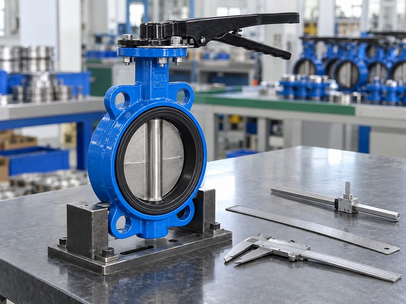
9. What can a butterfly valve diagram prove?
A controlled butterfly valve diagram can define intended construction and relationships within its stated scope. It cannot establish the actual supplied item’s wear, material identity or accepted leakage result by itself. Those judgments need the corresponding product, inspection or test evidence required for the selected assembly.
What evidence belongs beside a design interpretation?
Match the claim with its evidence. Use actual material records, dimensional checks and required movement or leakage results for their respective acceptance questions. Keep rated data tied to the selected configuration. A complete-looking diagram cannot establish passed inspection or capability at unrelated catalogue pressure, temperature, direction and fluid conditions.
- Separate intended design from the supplied item’s verified condition.
- Request the records relevant to each acceptance claim.
- Keep operating ratings linked to the actual configuration.
Key takeaway: Let the drawing define the design while actual records establish required condition and performance evidence.
| Check | What you should confirm |
|---|---|
| Design | Selected drawing defines its stated construction intent |
| Condition | Actual observations and checks address the supplied item |
| Performance | Required rated data and test results support the claimed duty |
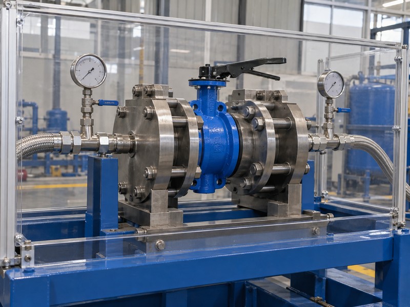
10. What if a butterfly valve diagram has missing labels?
Record missing labels in a butterfly valve diagram as specific unresolved questions tied to the applicable view and valve identity. Identify the uncertain feature and the decision it affects. A guessed callout or borrowed figure can turn a small documentation gap into a wrong construction or acceptance assumption.
What should a useful clarification request include?
Locate the unresolved feature. Retain the drawing title, model, view and relevant marked excerpt. State whether the question concerns identity, assembled contact, dimensions or required evidence. RUITO can review an identified request and available documents, with actual construction and supporting records confirmed for the proposed scope before any supply commitment.
- Identify the drawing, view and uncertain feature clearly.
- State the technical decision that the missing label prevents.
- Retain the accepted response with the relevant review records.
Key takeaway: Close missing-label questions through identifiable clarification instead of inserting generic parts or assumptions.
| Check | What you should confirm |
|---|---|
| Question | Missing information has a specific view and feature reference |
| Effect | Affected identity, relationship or acceptance decision is stated |
| Response | Accepted clarification remains linked to the actual construction |
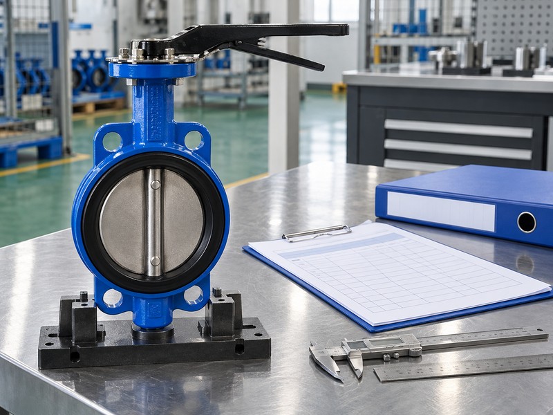
Send RUITO the identified valve request, available diagram, applicable parts list and the inside-view questions your team cannot resolve. We can review the proposed scope and clarify which actual construction and supporting documents would be needed for evaluation. Contact us before treating a generic diagram or unlabelled feature as a verified description of the assembly you need.
FAQ
Q1: Can I measure operating clearance from an exploded view?
No. Use the actual assembled detail and controlled dimensions; exploded spacing separates parts for identification.
Q2: What’s the best way to identify a numbered callout?
Use its own figure and parts list. Match the applicable model and variant notes before assigning the component identity.
Q3: How do I know if a missing support was left out of the valve?
Check the companion views and actual parts record. A section plane or simplified view can leave a component unshown.
Q4: Can a flow arrow establish every permitted pressure direction?
No. Read its legend and the selected model instructions; indicated flow, preferred pressure direction and reverse-duty limits are separate definitions.
Q5: How do I know whether the drawing proves the seat is leak-tight?
Request actual acceptance evidence. A design view defines intended relationships, while the selected test criteria and traceable results address sealing performance.