
Fix butterfly valve seat interface mistakes by identifying the actual sealing pair, retention and backing in the selected construction. Read shaft and flange sealing through their model-specific definitions. Confirm permitted service and acceptance evidence before treating a seat label as proof of fit, replaceability or performance.
A seat description can leave backing, body retention and flange-face function undefined. That gap can send a shaft leak toward the wrong assessment or turn field-replaceable into an unsupported access assumption. Map the actual interfaces before accepting a condition judgment or service scope.
1. What does a butterfly valve seat seal?
A butterfly valve seat forms the selected stationary side of the valve’s disc-to-seat shutoff interface. Its actual construction may also provide other defined sealing functions. Identify those functions separately before treating the seat, stem seal, body lining and flange seal as interchangeable component names.
Which interfaces belong in the seat definition?
Trace the selected sealing pair. Locate the disc sealing region and mating seat through the actual assembled section. Follow any additional seat-related function into its own drawing note or component description. One designed component may perform several duties, but each duty still needs a defined contact relationship and appropriate evidence rather than a generic assumption about every butterfly valve.
- Identify the actual disc-to-seat shutoff relationship.
- Record additional functions only where the model defines them.
- Keep component names and sealing duties explicitly connected.
Key takeaway: Start with the actual shutoff interface and identify any additional seat duties separately.
| Check | What you should confirm |
|---|---|
| Shutoff | Selected seat mates with the defined disc sealing region |
| Other duties | Additional sealing roles have a model-specific basis |
| Boundaries | Stem, body and pipe-interface functions remain identifiable |
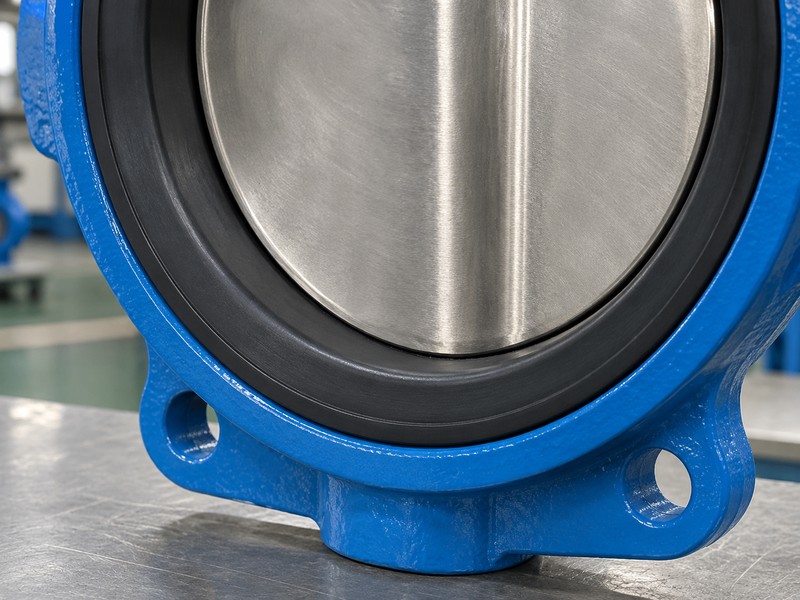
2. Where does a butterfly valve seat contact the disc?
A butterfly valve seat contacts the disc at the sealing region defined by the selected geometry and seat assembly. Its location and loaded relationship cannot be established from a dark ring or apparent contact line alone. Read the actual assembled section beside its material and acceptance definitions.
What should a contact-interface review distinguish?
Identify both mating surfaces. Match the disc sealing edge or surface with the actual seat region, including any defined interference, compression or loading condition. A nominally closed illustration cannot establish that the supplied surfaces achieve the required contact. Use the selected design and applicable verification rather than deriving contact pressure or an acceptable gap from an unscaled picture.
- Locate both mating regions through the selected drawing.
- Read applicable loading or interference definitions in context.
- Keep illustrated contact separate from verified assembled condition.
Key takeaway: Define contact through the selected sealing pair before judging an apparent line, gap or closed position.
| Check | What you should confirm |
|---|---|
| Disc region | Actual sealing surface has a defined relationship with the seat |
| Seat region | Selected construction identifies its mating contact area |
| Verification | Required fit and sealing evidence addresses the supplied assembly |
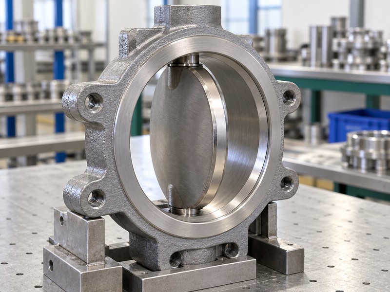
3. How is a butterfly valve seat retained?
A butterfly valve seat is retained through the body, seat features or separate components defined by its actual construction. Identify the assembled retention detail before interpreting an external label. Descriptions such as booted, molded and cartridge need the supplier’s specific definition rather than an assumed universal arrangement.
What must construction labels resolve in the drawing?
Read the retention detail. Identify any documented removable liner, bonded or molded-in arrangement, backed insert or separately retained seat. Record actual mating features and supporting callouts. Required reverse-pressure, vacuum or end-condition duty needs the selected model’s supporting data beyond a construction label.
- Connect the construction label with its actual assembled detail.
- Identify body, seat and any separate retaining features.
- Keep required operating and end-condition limits model-specific.
Key takeaway: Use construction labels to locate the relevant design definition rather than rank seat types universally.
| Check | What you should confirm |
|---|---|
| Label | Supplier terminology has a defined construction reference |
| Retention | Actual body and component features locate the selected seat |
| Duty | Required differential and end conditions have separate supporting data |
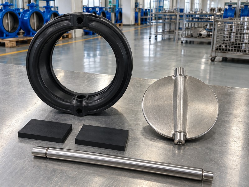
4. What backs a butterfly valve seat?
Any backing behind a butterfly valve seat belongs to the selected seat assembly and may have a separately defined support or energizing role. Confirm whether a callout identifies the sealing element, its backing or a complete assembly. Visible shape and a broad material name cannot establish that relationship by themselves.
How should support and sealing components stay distinct?
Follow the complete seat assembly. Read the component list and section for included backing, energizers and retainers. Preserve their functions and material boundaries; a surrounding ring may have a supporting role. Fit, service and acceptance evidence must cover the selected combination and its defined interactions.
- Identify the actual sealing element and included support pieces.
- Distinguish individual components from a complete seat assembly.
- Retain the selected material and interaction definitions.
Key takeaway: Read backing and energizing features through their actual component functions within the complete seat assembly.
| Check | What you should confirm |
|---|---|
| Sealing element | Actual component provides the defined mating surface |
| Support | Included backing or energizer has an identified design function |
| Assembly | Applicable records cover the selected combined construction |
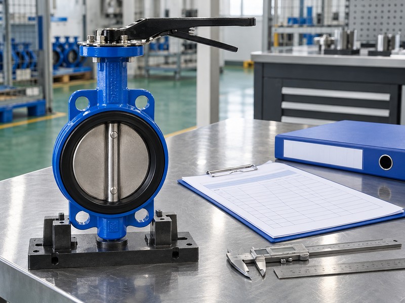
5. Does a butterfly valve seat seal the shaft?
Whether a butterfly valve seat contributes to shaft-area sealing depends on the actual model’s design. A seat-related shaft or hub interface and a separate stem seal can have different duties. Do not attribute every external shaft leak to the disc-to-seat shutoff interface.
Which shaft-area relationships need their own identification?
Map the defined shaft interfaces. The Bray Series 20/21 description identifies its named hub/seat and shaft/seat sealing relationships alongside a stem seal and bushing. Keep that arrangement within its model context. For the actual valve, distinguish movement support, process sealing and external leakage observations through the selected component records and authorized assessment.
- Identify seat-related shaft or hub functions where specified.
- Read separate stem seals and supports through actual records.
- Keep external shaft leakage distinct from shutoff leakage.
Key takeaway: Identify shaft-area functions separately before assigning a leak to the seat or another component.
| Check | What you should confirm |
|---|---|
| Seat relationship | Any hub or shaft sealing duty has a model-specific basis |
| Separate parts | Stem seals and supports retain their defined functions |
| Observation | Actual leakage location remains distinct from an assumed cause |
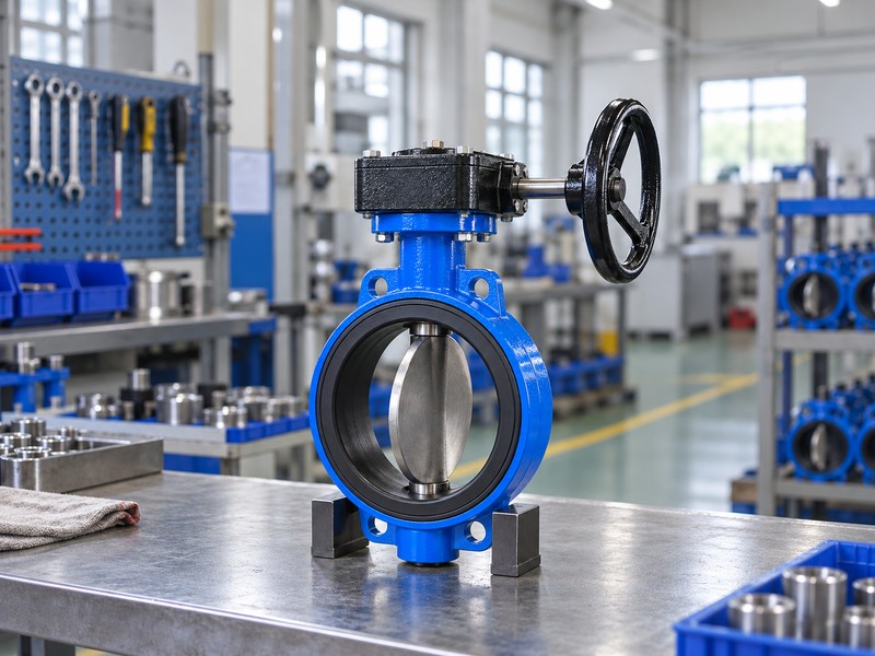
6. Can a butterfly valve seat seal the flange?
A butterfly valve seat can contribute to pipe-flange sealing where the selected construction explicitly provides that function. Other arrangements have separately defined flange-gasket requirements. Read the actual body face and seat-face details before accepting or changing a gasket arrangement.
What makes a seat-face sealing example model-specific?
Check the mating face definition. Emerson’s isolation-valve portfolio identifies seat-face sealing for its Keystone Figure 990/920 construction. Other resilient, lined or high-performance models need their own interface definition. Retain actual mating-face, gasket and assembly requirements instead of changing a gasket arrangement from a generic seat description.
- Identify any seat-face function at the pipe interface.
- Read actual body and mating-flange sealing requirements.
- Keep gasket decisions within the selected assembly instructions.
Key takeaway: Treat flange sealing as a defined interface rather than a universal consequence of having a resilient seat.
| Check | What you should confirm |
|---|---|
| Seat face | Any flange-sealing feature belongs to the identified construction |
| Mating parts | Actual faces suit the selected interface requirements |
| Gasket | Required arrangement follows the model-specific instructions |
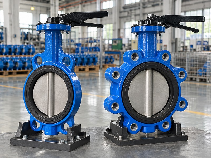
7. Is a butterfly valve seat replaceable?
Replaceability of a butterfly valve seat depends on the exact construction and its permitted service method. Confirm the model, seat variant and applicable instructions before accepting a field-replaceable label. A bonded appearance does not establish an automatic discard decision, and removable-looking parts do not authorize in-line service under pressure.
What must the service statement actually cover?
Read the selected service scope. The Bray resilient-seat manual separates family-specific procedures and seat arrangements. Obtain actual replacement identity, required access, component pairing and post-service verification. Physical work requires selected instructions and authorized isolation, depressurization, draining/decontamination and energy controls; this article supplies no removal sequence.
- Confirm actual seat variant and permitted service method.
- Identify required access, replacement identity and affected rechecks.
- Keep physical work within authorized selected procedures.
Key takeaway: Interpret replaceability through the actual service scope rather than a construction label alone.
| Check | What you should confirm |
|---|---|
| Construction | Service statement covers the actual model and seat variant |
| Access | Selected method defines the permitted work arrangement |
| Acceptance | Required post-service checks have an identified basis |
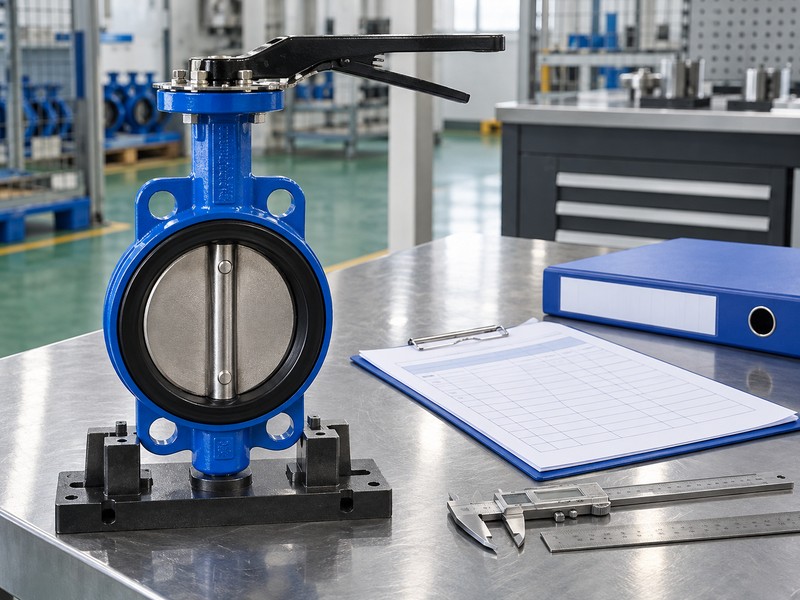
8. What verifies a butterfly valve seat condition?
A butterfly valve seat condition assessment needs the actual component identity, observed feature and applicable acceptance criteria. Record visible marks or deposits without assuming their cause or service significance. A photograph cannot establish concealed backing condition, installed compression or every surface in the sealing pair.
Which observations should remain separate from acceptance?
Locate the observed feature. Link its position on the disc-contact region, seat face, shaft opening or other identified feature with the actual assembly record. Retain the authorized inspection context and any required measurement or test evidence. The selected criteria govern acceptance and follow-up; a generic image cannot provide a universal scratch depth, wear limit or permission to return the valve to service.
- Record actual location and appearance of the observed feature.
- Separate visible condition from concealed assembly questions.
- Use selected criteria and required evidence for acceptance.
Key takeaway: Assess the actual seat interface through traceable observations and selected criteria rather than appearance alone.
| Check | What you should confirm |
|---|---|
| Observation | Feature and location connect with the actual seat assembly |
| Evidence | Required measurements or tests address the acceptance question |
| Decision | Applicable criteria govern service or follow-up judgment |
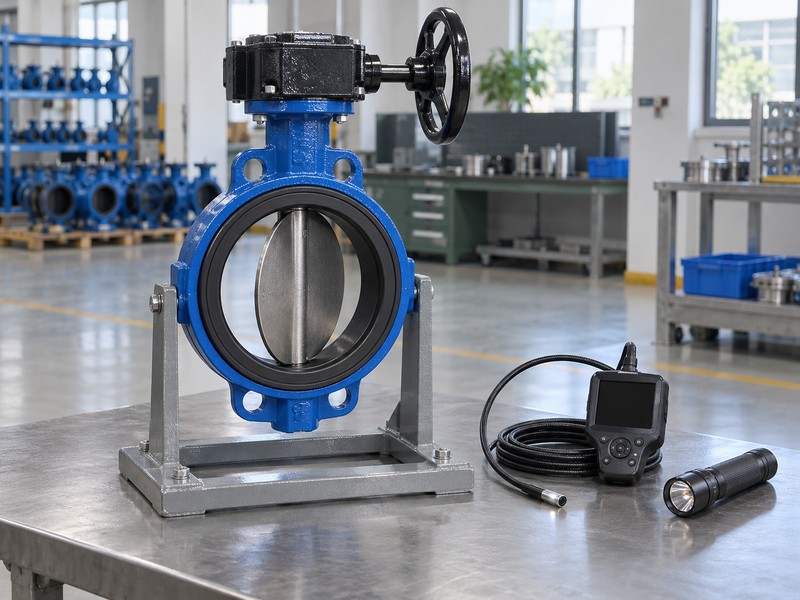
9. Can a butterfly valve seat view prove shutoff?
A butterfly valve seat view cannot establish accepted shutoff performance by showing an apparently continuous contact region. Required leakage evidence belongs to the selected sealing pair and test definition. Keep internal shutoff, external shaft leakage and body or flange leakage separately identified.
Why does a flow-loss curve answer another question?
Match performance with the correct evidence. The conceptual chart describes pressure loss versus flow at fixed opening, flow coefficient and liquid density; it provides no leakage curve or measured model data. Shutoff acceptance requires the applicable medium, differential, direction, temperature and criterion with recorded results. Neither an open-flow illustration nor the apparent softness of a seat can supply that test evidence.
- Identify the exact leakage path and required acceptance basis.
- Retain applicable test conditions and actual results.
- Keep flowing pressure loss separate from closed-seat leakage.
Key takeaway: Use the selected test record for shutoff acceptance and the image for its stated visual scope.
| Check | What you should confirm |
|---|---|
| Shutoff | Selected sealing pair has a defined leakage acceptance requirement |
| Other paths | Shaft, body and flange observations retain separate identities |
| Flow loss | Capacity context cannot replace leakage-test evidence |

10. What closes a butterfly valve seat review?
Close a butterfly valve seat review when the contact, retention, backing and additional sealing duties have accepted configuration references. Record which condition judgments remain dependent on inspection or testing. A complete-looking component description cannot establish compatibility, permitted service or required performance without supporting records.
What should the next technical decision receive?
Retain the interface definition. Link actual valve and seat identity with its assembled section, component records, authorized observations and required verification. Assign unresolved interface or service questions without assuming interchangeability. RUITO can review an identified request and available documents, with actual construction and supporting records confirmed before a supply commitment.
- Link the actual seat with its complete assembly definition.
- Retain the evidence supporting each accepted interface judgment.
- Assign unresolved contact, retention and service questions explicitly.
Key takeaway: Close the seat review through a traceable interface definition and the evidence required for the next decision.
| Check | What you should confirm |
|---|---|
| Definition | Contact and supporting functions match the actual construction |
| Evidence | Accepted judgments retain their document or test basis |
| Follow-up | Unresolved questions have an assigned technical owner |
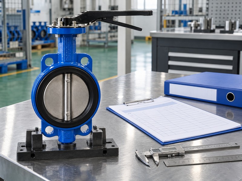
Send RUITO the identified valve request, seat-interface question, available assembled section and relevant service or inspection records. We can review the proposed scope and clarify which actual construction and supporting documents would be needed for evaluation. Contact us before treating a seat label or generic illustration as proof of the interface or service arrangement you need.
FAQ
Q1: Can I use a seat label to decide which design is best?
Not by the label alone. Confirm actual contact, retention, backing and required duty through the selected construction and supporting records.
Q2: What’s the best way to distinguish shaft leakage from seat leakage?
Identify the observed path. External shaft leakage and internal flow across the closed sealing pair need separate assessment and acceptance evidence.
Q3: How do I know if the seat also seals against the pipe flange?
Check the actual mating-face definition. Some named constructions provide that function, while other models have separate flange-gasket requirements.
Q4: Can I assume field-replaceable means in-line replacement?
No. The actual model’s instructions define permitted access, isolation, service method and required verification after work.
Q5: How do I know if a seat needs separate backing or an energizer?
Read the selected assembly. Its section and component records identify any included support or energizing elements and their actual functions.