
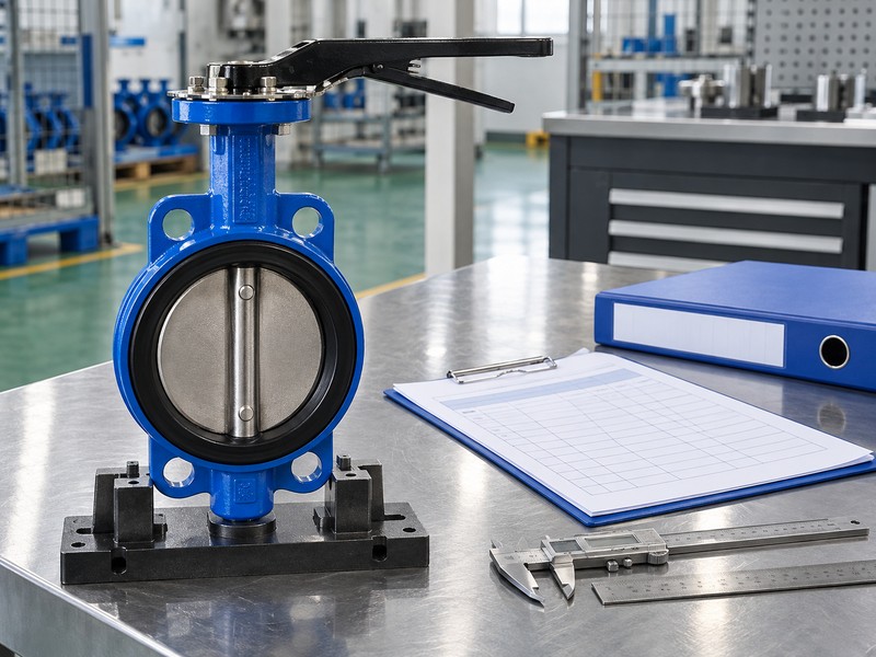
Identify each component’s function, assembly identity and supply grouping before requesting a quotation. Match butterfly valve parts with the selected model, parts list and applicable revision. A name such as seat or shaft cannot establish ordering identity, material or kit compatibility.
A request for a seat and shaft can leave the supplier unsure about separate components, a combined unit or a kit. A quotation may then describe a different quantity or supply boundary from the maintenance schedule. Identify each requested item and supply grouping so purchasing and engineering review the same scope.
1. What identifies butterfly valve parts?
Identify butterfly valve parts through the actual valve model, construction and applicable parts-list revision. Functional names explain roles; manufacturer references identify the selected supply. Keep those fields separate in the purchasing schedule.
Which fields belong in the parts schedule?
Start with assembly identity. Record manufacturer, model, size, body style and available valve or product identification before listing requested components. Add the applicable parts definition and relevant service information, then retain unresolved details for supplier clarification. Generic images or another family’s part names cannot establish ordering identity.
- Identify the actual valve and applicable parts record.
- Separate functional names from manufacturer ordering identities.
- Retain missing details as explicit clarification requests.
Key takeaway: Identify components within the actual valve configuration.
| Check | What you should confirm |
|---|---|
| Function | Component name explains its mechanical or sealing role |
| Identity | Selected manufacturer reference identifies the applicable item |
| Schedule | Model, revision and required quantity connect the request |
2. How are butterfly valve parts counted?
The count of butterfly valve parts depends on the selected construction and how its manufacturer groups components. A function can share one physical unit with another function, while a body can comprise several listed pieces. A universal count cannot describe every resilient, lined or retained-seat arrangement.
Why can the same names produce different item counts?
Use the selected parts definition. The Bray resilient-valve manual shows a split-body Series 20/21 with a disc/stem unit, while Series 30/31 identifies separate disc and stem components with its own retention pieces. Those are named constructions rather than interchangeable parts maps. Count components, supplied assemblies and kit contents in separate fields.
- Distinguish functions, physical pieces and supplied assemblies.
- Read quantities from the applicable model’s parts record.
- Keep kit contents separate from the number of kits ordered.
Key takeaway: Count against the actual model and confirmed purchase unit.
| Check | What you should confirm |
|---|---|
| Function count | Describes roles such as closure, drive and sealing |
| Component count | Follows the actual selected construction |
| Order quantity | States the number of identified supply units required |
3. Which butterfly valve parts form the body?
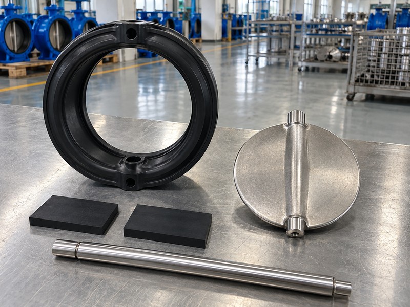
Body-related butterfly valve parts provide the selected pressure boundary, connection features and internal support locations. Body construction and connection style describe different features, so a split body still needs its actual wafer, lug or other interface identified. Name the body through the actual model and its parts definition.
How should body pieces and joint items be named?
Retain the manufacturer’s body terminology. List upper or lower body pieces only where the selected construction identifies them, and include body-joint items when they appear in that parts definition. Assign pipe-connection hardware and flange sealing items their own scope. Connection style alone cannot establish internal geometry, required gaskets, end-of-line capability or operating limits for another valve.
- Identify the actual body construction and listed pieces.
- Include defined body-joint items without inventing hidden components.
- Separate body parts from external pipe-connection scope.
Key takeaway: Name body components through the selected construction and supply boundary.
| Check | What you should confirm |
|---|---|
| Pressure boundary | Selected body pieces have identified material and construction |
| Body joint | Applicable seals and fasteners follow the actual parts definition |
| Connection | Pipe-interface items retain their separately stated scope |
4. Which butterfly valve parts affect flow?
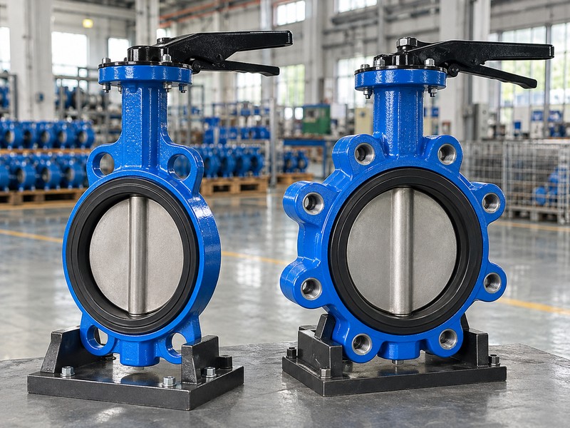
The disc and relevant shaft or support features among butterfly valve parts influence the available flow passage. Opening rotates the disc through its permitted movement rather than removing every internal obstruction. A valve shown open cannot be treated as an empty full-bore pipe with no pressure loss.
What should the schedule record about the disc?
Identify the actual closure element. Record disc identity, material and any defined surface treatment or combined stem relationship within the selected configuration. The conceptual chart shows pressure loss rising with flow at a fixed opening, flow coefficient (Cv) and liquid density; it supplies no model data. That flow relationship cannot establish closed-seat leakage, material compatibility or a permitted control range for the requested component.
- Identify disc material and any specified surface treatment.
- Retain its actual shaft or combined-unit relationship.
- Use selected-product data for flow and operating restrictions.
Key takeaway: Identify the closure element and obtain its selected performance data.
| Check | What you should confirm |
|---|---|
| Closure element | Selected disc identity matches the actual construction |
| Passage | Disc and relevant support features occupy flow space |
| Performance | Actual flow information belongs to the selected model and duty |

5. Which butterfly valve parts provide sealing?
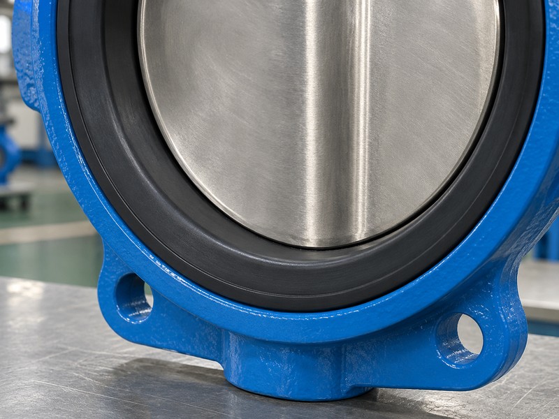
Sealing functions among butterfly valve parts can include the closed disc-to-seat pair, shaft sealing and body or flange interfaces. One designed component may serve more than one function, but those functions remain distinct. Seat, liner, bonded lining and coated disc descriptions cannot be exchanged without checking the actual construction.
How should seat and interface seals be distinguished?
Name the sealing function explicitly. The Keystone Figure 990/920 portfolio example identifies a replaceable seat and seat-face sealing feature for that named design. It establishes no universal replaceability or no-gasket rule. Retain the selected seat, backing, retention and interface requirements rather than inferring them from rubber color or a smooth contact illustration.
- Identify seat and liner construction through actual records.
- Separate shutoff sealing from shaft and interface sealing.
- Check replaceability and gasket requirements for the selected model.
Key takeaway: Record distinct sealing functions even where components share them.
| Check | What you should confirm |
|---|---|
| Shutoff | Selected disc and seat form the defined sealing pair |
| Shaft | Applicable sealing components address external shaft leakage |
| Interfaces | Body and pipe joints follow their selected sealing arrangements |
6. Which butterfly valve parts drive and support the disc?
Drive and support functions among butterfly valve parts can involve a stem or shaft, disc attachment, retaining pieces, bushings and bearings. Their actual number and arrangement remain model-specific. A support component and a sealing component can both surround a shaft while performing different duties.
What should remain separate in component descriptions?
Separate drive, support and sealing roles. Identify whether the selected design uses a combined disc/stem or separate connected parts, then name the actual retention and locating items it lists. Keep radial or axial support descriptions distinct from shaft seals or any identified packing arrangement. Do not add a universal gland stack, pair of bearings or hidden fastener simply because another valve uses one.
- Identify the actual disc-to-stem or combined-unit arrangement.
- Retain listed retaining, locating and support components.
- Distinguish shaft support from the selected external-sealing function.
Key takeaway: Describe the selected drive, support and sealing arrangement without adding undocumented parts.
| Check | What you should confirm |
|---|---|
| Drive | Actual connection transfers operator movement to the disc |
| Support | Selected components locate and support the moving arrangement |
| Sealing | Applicable seals retain their separately defined leakage duty |
7. Where do butterfly valve parts meet the operator?
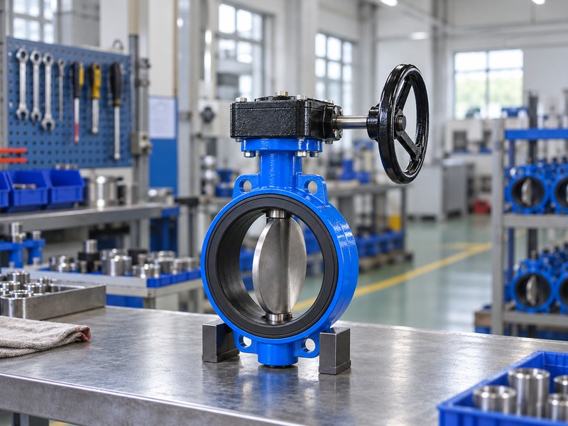
The schedule for butterfly valve parts should state whether the lever, gearbox, actuator and mounting components belong to the requested supply. The valve’s stem drive and the operator’s mating connection form an interface. Naming an operator does not identify every coupling, bracket, indicator or associated accessory.
How should the valve and operator boundary be recorded?
Define the supplied boundary. Identify retained and requested operator items, mounting parts and the selected interface documents without treating a position pointer as proof of disc connection or sealing. Required torque, travel and limits follow the actual valve and operator records. Any physical service follows the selected manual and an authorized isolation, depressurization, draining or decontamination and energy-lockout process, including actuator or stored-energy controls where applicable.
- Assign valve, operator and mounting items to their supply scope.
- Identify actual stem and mating operator interface records.
- Keep physical service within selected instructions and authorized controls.
Key takeaway: Define the supply boundary between valve, operator and mounting components.
| Check | What you should confirm |
|---|---|
| Valve boundary | Requested internal and stem-drive items are identified |
| Operator boundary | Lever, gearbox or actuator supply is explicitly stated |
| Interface | Mounting and coupling components have an assigned scope |
8. Which materials define butterfly valve parts?
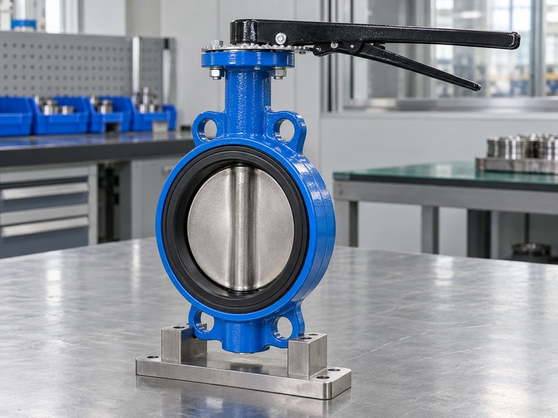
Material definitions for butterfly valve parts must identify actual grades, compounds and any coating or lining arrangement within the selected configuration. A structural body material and the fluid-contact material list can answer different questions. A familiar elastomer name or metallic appearance cannot establish the complete material specification.
Which service details belong beside material identities?
Connect materials with the actual duty. Retain wetted-part definitions, medium composition, temperature and applicable pressure or differential information for the model being reviewed. RUITO’s concentric, double-flanged double-offset and lined configurations retain separate material and service boundaries. A coated disc with a different seat material cannot automatically be described as a fully lined assembly, and an illustration cannot establish alloy or seal-compound identity.
- Record actual grades, compounds, coatings and lining definitions.
- Identify which listed components contact the process medium.
- Retain selected media and operating-limit documents with the schedule.
Key takeaway: Link each material with its component, exposure and actual duty.
| Check | What you should confirm |
|---|---|
| Identity | Material records describe actual grades or compounds |
| Exposure | Wetted and external duties remain separately identified |
| Application | Selected service conditions support the material review |
9. How are butterfly valve parts grouped for orders?
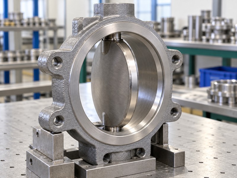
Orderable butterfly valve parts can be individual items, defined assemblies or manufacturer kits, depending on the selected construction. A drawing item number can locate a component without being its sales order number. Record the actual supplied unit and included contents so quantities remain unambiguous.
When must matched components stay grouped?
Use the manufacturer’s supply definition. The Bray McCannalok manual specifies matched disc/stem replacement for its identified standard arrangement; that requirement is not a universal parts grouping. Other models need their own permitted component or kit definitions. Ask the supplier to confirm ordering identity, included hardware and required pairing rather than treating items with similar names as independent interchangeable purchases.
- Separate illustration item references from ordering identities.
- State the supplied unit and included kit contents.
- Retain model-specific pairing and grouping requirements.
Key takeaway: Order confirmed supply units and retain required matched-component groupings.
| Check | What you should confirm |
|---|---|
| Item reference | Locates a component in the applicable parts record |
| Order identity | Supplier confirms the actual purchasable item or assembly |
| Contents | Quantity and required grouped components are explicitly stated |
10. What records track butterfly valve parts?
Trace butterfly valve parts from the accepted component schedule through quotation, supplied identity and handover records. Keep the actual model and revision alongside order identities, quantities and material definitions. Changes to a seat, drive unit or kit need review against the same configuration baseline.
Which records should accompany the agreed supply?
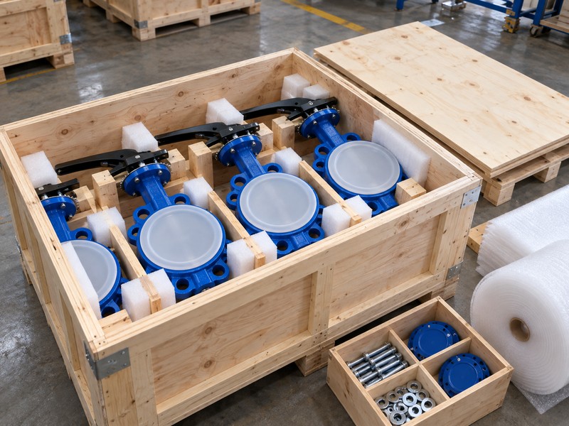
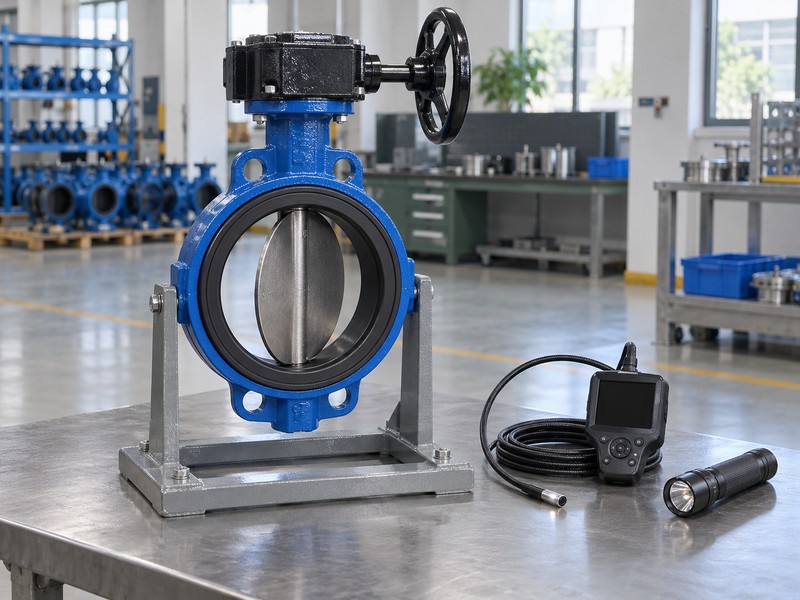
Retain the accepted parts scope. Keep supplier-confirmed item or kit descriptions, applicable parts records, required material information and agreed inspection evidence linked with the order or supplied product identity. Internal leakage, external shaft leakage and body or flange leakage require their own selected acceptance definitions where those checks apply. A generic inspection-bench illustration supplies no actual measurement, test result, stock confirmation or evidence of RUITO manufacture.
- Link confirmed supply identities with the applicable model revision.
- Retain quantities, materials and accepted technical exceptions.
- Keep required inspection evidence within its stated acceptance scope.
Key takeaway: Retain identified, quoted, supplied and accepted parts records for the actual configuration.
| Check | What you should confirm |
|---|---|
| Quotation | Confirmed identities and supply units match the request |
| Delivery | Labels and records describe the accepted supplied items |
| Handover | Applicable parts and inspection information remain traceable |
Send RUITO the valve markings, model or available product identity, applicable parts record, service conditions and required quantities. We can review the supplied application information and clarify the proposed component or kit scope. Contact us for confirmation of actual configuration, supply availability and supporting records before placing the order.
FAQ
Q1: Does every butterfly valve have the same number of parts?
No. Physical components, combined units, body construction and supplied kits vary by model. Use the applicable parts definition.
Q2: Is a stem seal the same as a bushing?
They have different functions. A bushing supports the moving arrangement, while a stem seal addresses its defined external-leakage path.
Q3: Is every butterfly-valve seat independently replaceable?
No. Replaceability, pairing and permitted service scope follow the selected model’s parts information and maintenance instructions.
Q4: Is a drawing item number enough to place an order?
Not always. Ask the supplier to confirm ordering identity, applicable model and revision, supply unit and included contents.
Q5: Does the same size and material name prove compatible parts?
No. Confirm actual construction, component identity, grade or compound, required pairing and selected service limits for the application.