
A butterfly valve disk is the rotating closure inside the valve body. It controls the flow opening and meets the seat when closed. If a replacement looks right but binds during assembly, compare its geometry, shaft connection and sealing edge with the approved drawing before ordering another part. A manufacturing and inspection plan should connect those features to measurable acceptance criteria.
1. What does a butterfly valve disk do inside the valve?
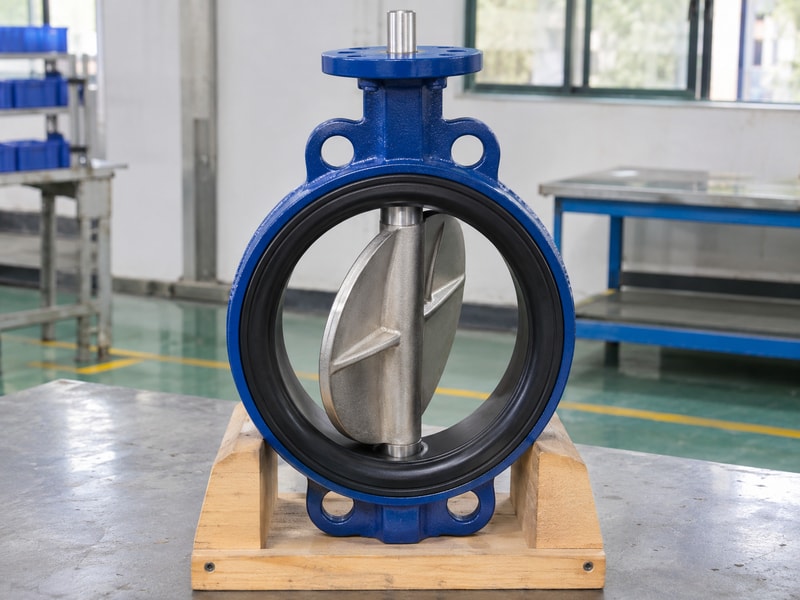
The butterfly valve disk rotates with the shaft and changes the available flow area. Near closure, its sealing surface engages the seat according to the valve design. In a concentric resilient-seated valve, that relationship differs from an offset valve with a separate seat arrangement. You need the correct cross-section before interpreting a photograph or choosing a spare.
Read the whole assembly
Check the disk together with the seat, shaft, bearings and operator. A bare casting has no standalone shutoff rating because the assembled valve establishes sealing performance. Even at full opening, the disk and shaft occupy part of the bore.
Flow capacity therefore depends on the actual shape, opening angle and service conditions. Use the configuration details for your wafer butterfly valve when reviewing those relationships.
- Identify the valve structure and nominal size.
- Confirm the shaft axis and seat arrangement.
- Obtain the assembly drawing revision.
| Feature | Function | Procurement check |
|---|---|---|
| Disk profile | Shapes the flow passage | Approved section |
| Sealing edge | Contacts the seat | Matched geometry |
| Shaft connection | Transfers operating torque | Actual joint detail |
Keep the disk and its mating parts on the same approved configuration.
2. Which dimensions determine butterfly valve disk fit?
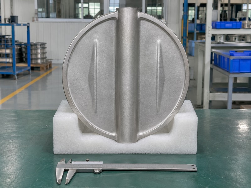
Butterfly valve disk fit depends on the sealing diameter, profile, shaft position and connection details. Nominal size alone cannot define those dimensions. Two disks for the same DN can have different edge forms, hub lengths or retention arrangements. Treat a visually similar part as a candidate for measurement rather than an interchangeable spare.
Define datums before tolerances
The drawing should show where each dimension starts. Establish the shaft-axis datum and the relevant sealing reference before comparing measurements. A diameter reading without its measurement position may miss a shaped sealing edge.
Check the disk sweep against the body, seat and adjoining pipe bore. For a lug butterfly valve, the assembly review also needs the correct flange and bolt arrangement.
- Record sealing diameter at the stated reference.
- Compare hub and shaft connection dimensions.
- Check the complete rotational envelope.
| Dimension | Why it affects fit | Needed evidence |
|---|---|---|
| Edge geometry | Controls seat engagement | Section and tolerance |
| Axis location | Sets rotational path | Datum definition |
| Hub interface | Locates the drive joint | Connection drawing |
A measured disk diameter cannot replace an assembly clearance check.
3. How is a cast butterfly valve disk produced?
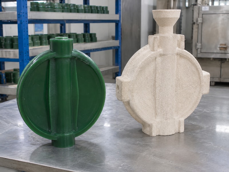
A cast butterfly valve disk starts with a controlled pattern and casting process, followed by finishing and the specified inspections. Investment casting uses an expendable pattern and ceramic shell. Other approved routes may suit different sizes and production requirements. Choose the process against the component drawing and acceptance plan rather than assuming one method suits every disk.
Control the route from pattern to finished part
Pattern dimensions, feeding design and process controls affect the casting that reaches machining. Agree on machining allowance and which surfaces will remain as cast. Specify any required heat treatment and trace the material batch through subsequent operations.
Neither a smooth sample nor an attractive shell photograph establishes dimensional capability. Ask the supplier how a change to tooling, alloy or heat treatment enters the approval process.
- Freeze the pattern and drawing revision.
- Define machining allowances and inspection stages.
- Link material records to the supplied batch.
| Stage | Controlled output | Review point |
|---|---|---|
| Pattern production | Repeatable component form | Revision control |
| Casting and treatment | Specified material condition | Batch traceability |
| Finishing | Machining-ready component | Defect acceptance |
Write the acceptance criteria before approving a production sample.
4. What must machining preserve on the disk?
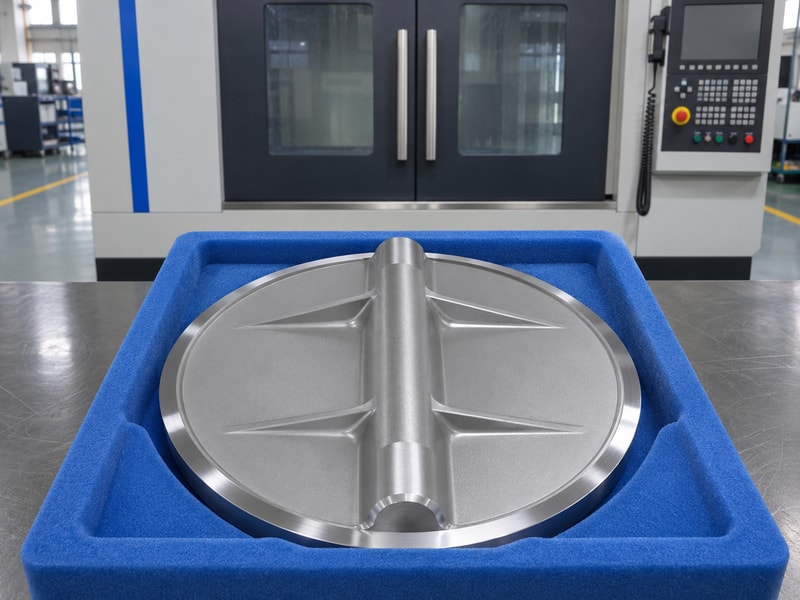
Machining must give the butterfly valve disk its specified interfaces while preserving the sealing profile and required section thickness. The shaft joint, sealing edge and locating surfaces need coordinated tolerances. Removing extra metal to make one dimension fit can change another interface. Any proposed rework should return to the drawing owner for review.
Inspect after the last relevant operation
Plan the setup so clamping and handling do not damage finished sealing surfaces. Check dimensions again after operations that can change the component, including any specified finishing or coating. Measure the shaft connection using the appropriate method for its actual form.
A keyed, pinned or other retained joint needs its own drawing details. Do not infer the permitted operating torque from the visible size of the hub.
- Protect finished sealing and locating surfaces.
- Verify the actual drive-joint dimensions.
- Reinspect features affected by later processing.
| Machined feature | Typical concern | Acceptance basis |
|---|---|---|
| Sealing profile | Shape or handling damage | Approved drawing |
| Shaft interface | Fit and alignment | Joint specification |
| Locating surface | Assembly position | Datum-based measurement |
Record final dimensions against the finished part condition.
5. How does butterfly valve disk material affect service?
Butterfly valve disk material affects corrosion resistance, mechanical properties and the suitability of the exposed surface. It must match the fluid and operating conditions together with the seat, shaft and other wetted parts. A stainless appearance does not identify an alloy. A coating colour cannot identify its formulation, coverage or service limits.
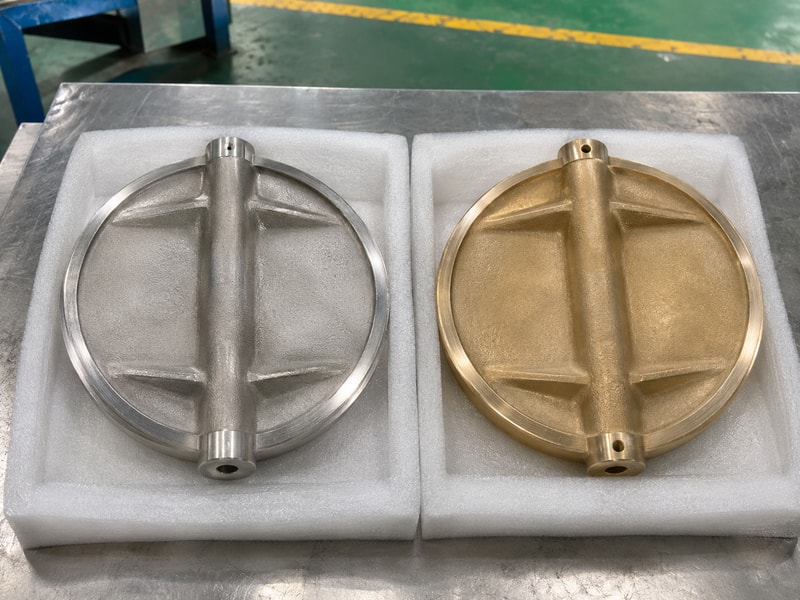
Separate the substrate from the wetted surface
For a bare metal disk, review the specified grade and condition. For an encapsulated disk, review the metal core and the complete protective construction separately. Chemical duty also requires the valve lining, backing and shaft seals to be compatible.
The construction of a PTFE lined butterfly valve needs that complete wetted-boundary review. Do not transfer a lined valve’s service limits to a bare metal version.
- State the exact fluid composition and temperature.
- Identify substrate and protective materials separately.
- Confirm every exposed wetted component.
| Construction | Material question | Evidence to request |
|---|---|---|
| Bare alloy | Which grade and condition? | Material record |
| Coated metal | Which coating and coverage? | Coating specification |
| Encapsulated metal | How is isolation maintained? | Controlled section |
Select the complete wetted construction for the stated service.
6. Why must the seat and pipe bore match the disk?
The butterfly valve disk needs the intended seat contact and enough clearance for its full travel. A disk that clears the valve body can still strike an adjoining flange or pipe bore. Seat interference can also change operating effort. Check the actual installation dimensions before treating resistance as an actuator problem.
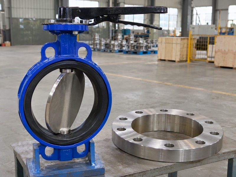
Review the installed envelope
Use the manufacturer’s installation instructions and approved flange details. Confirm the adjoining bore, any lining and the permitted gasket arrangement. The correct flanged butterfly valve drawing should show the relevant connection and installation envelope.
Keep bolts, alignment and operator settings within that assembly’s instructions. Do not use extra tightening force or a larger actuator to overcome unexplained contact.
- Compare actual adjoining bore dimensions.
- Review lining and gasket intrusion.
- Verify unobstructed travel by the approved procedure.
| Interface | Possible interference | Required check |
|---|---|---|
| Disk and seat | Incorrect engagement | Matched components |
| Disk and pipe | Insufficient sweep clearance | Actual bore |
| Valve and flange | Misalignment or intrusion | Installation drawing |
Resolve contact before placing the assembly in service.
7. Which butterfly valve disk defects need inspection?
Butterfly valve disk inspection should address the surfaces and defect types named in the acceptance specification. Inspect the sealing edge, shaft connection and accessible casting surfaces after cleaning. A visible scratch needs assessment against its location and permitted limits. A photograph cannot establish subsurface soundness or replace a specified inspection method.
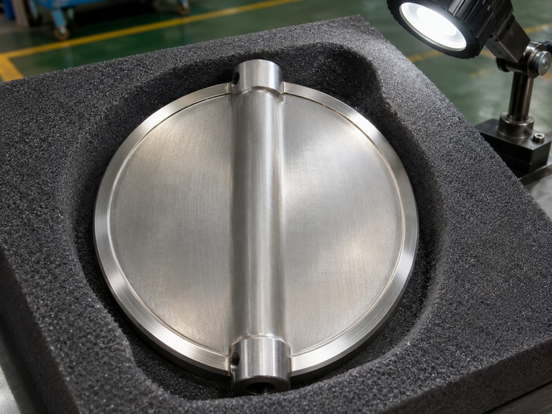
Use a defined inspection plan
Set the lighting, surface condition and acceptance criteria before inspection starts. Where the contract requires additional examination, identify the method, coverage, personnel requirements and reporting format. Record indications against the component or batch so a later review can find them.
Keep cosmetic observations separate from dimensional and functional acceptance. A polished surface can still have an unsuitable edge profile or an incorrect shaft interface.
- Clean and protect the inspection surfaces.
- Identify the location of any observed damage.
- Apply the specified acceptance and rework rules.
| Observation | What it establishes | Follow-up |
|---|---|---|
| Surface mark | Visible local condition | Compare with criteria |
| Dimensional deviation | Difference from drawing | Engineering disposition |
| Test indication | Result of a named method | Apply that method’s limits |
Use documented acceptance rather than a general statement that the part looks good.
8. How should butterfly valve disk dimensions be verified?
Verify butterfly valve disk dimensions with suitable equipment and verify movement in the correct assembly. These checks answer different questions. A dimensional report establishes conformity of the measured features.
An assembly check establishes the observed fit and travel under its stated conditions. Neither result alone proves shutoff performance across all service conditions.
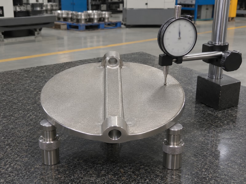
Connect each result to its conditions
Record the drawing revision, measurement locations and equipment identification. For movement checks, state the seat, shaft, operator and assembly condition. Operating torque depends on more than the disk, so request data for the actual valve configuration and specified differential pressure.
Pressure and closure tests need their own procedure and acceptance limits. Test pressure must never be presented as the allowed working pressure.
- Identify measurement datums and instrument suitability.
- Record the assembled configuration and travel checks.
- Keep dimensional, torque and leakage results distinct.
| Verification | Answers | Does not establish alone |
|---|---|---|
| Dimensional report | Does the measured feature conform? | Full valve performance |
| Travel check | Does this assembly move correctly? | All operating loads |
| Closure test | Does it meet stated test criteria? | Unlimited service suitability |
Keep the original conditions attached to every reported result. If the contract specifies ISO 5208, apply its valve pressure-test requirements with the applicable product requirements. That standard’s scope concerns pressure-boundary integrity and closure performance.
9. What should you request before accepting a disk order?
A butterfly valve disk order should define the component, its mating assembly and the evidence required for acceptance. Request the approved drawing, material specification, processing requirements and inspection plan. State how substitutions and repairs receive approval. A low component price becomes difficult to compare when those responsibilities remain undefined.
Close the technical gaps before production
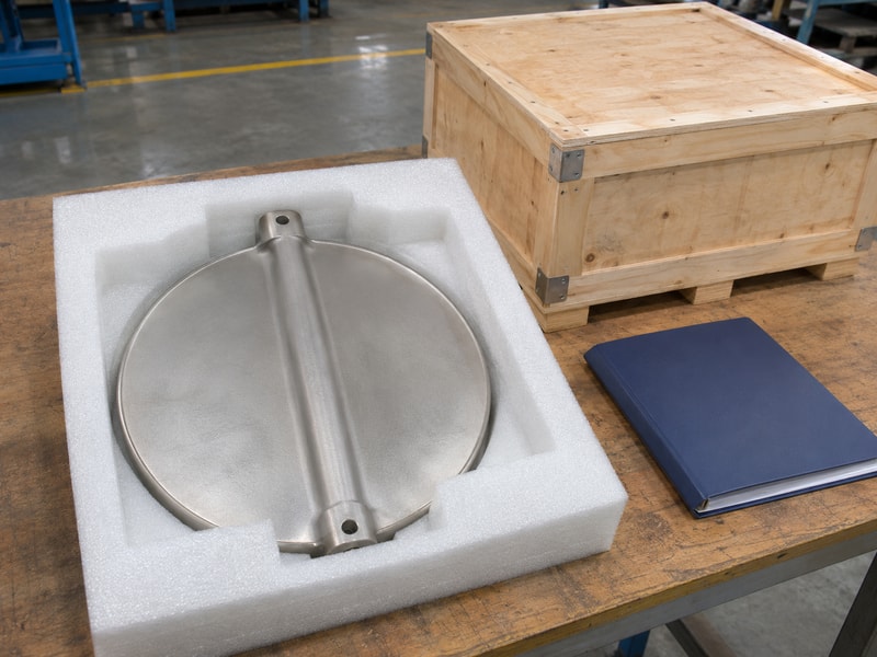
Include quantity, delivery condition and packaging that protects the sealing edge. Identify which measurements or tests require records and which require witnessing. For replacement work, provide the original valve identification and available drawings before offering a sample as the sole specification.
RUITO can review the requested valve construction and service requirements with your procurement team. Send the assembly details when you contact us for a configuration review.
- Confirm the approved drawing and material condition.
- Agree on inspection records and change control.
- Specify edge protection and part identification.
| RFQ item | What to provide | What to agree |
|---|---|---|
| Component identity | Drawing and valve details | Exact supply scope |
| Service | Fluid, temperature and pressure | Applicable configuration |
| Acceptance | Inspection requirements | Records and approval points |
Release the order after the supplier has answered the open technical items.
10. What else should you know before replacing the disk?
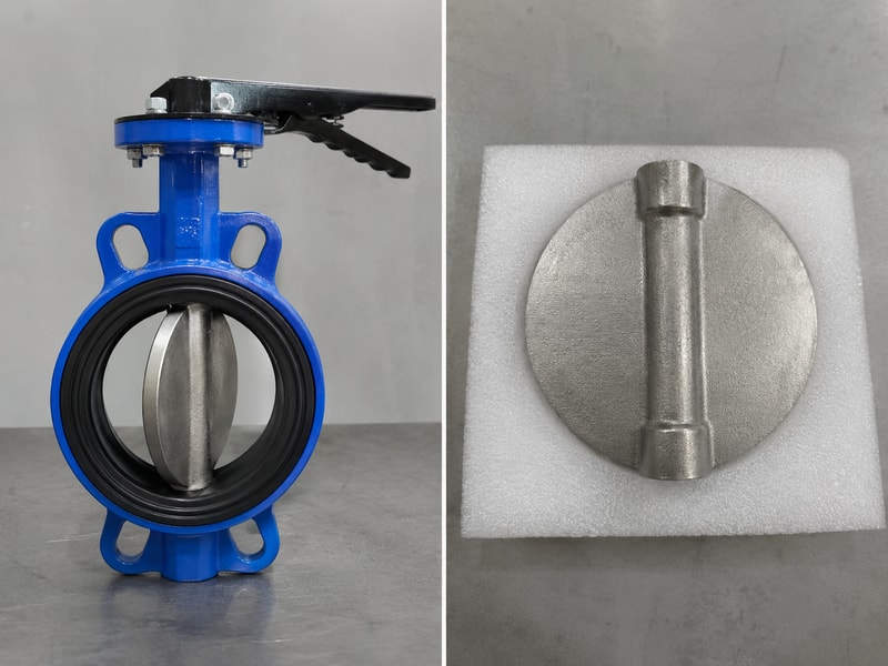
Before replacing a butterfly valve disk, settle the questions that affect your maintenance plan. Confirm the replacement procedure, required isolation and the condition of the mating parts. Keep the original component identification available during inspection. If the drawing or repair limits are missing, resolve that gap before removing material or approving a substitute.
Q1: Can I replace a butterfly valve disk with one of the same DN?
Only after confirming compatibility. The same nominal size can have different sealing profiles, shaft joints and rotational envelopes. Obtain the correct component drawing and the valve manufacturer’s replacement procedure.
Q2: How do I know if the disk is causing a leak?
You need an inspection of the complete sealing system. Seat damage, foreign material, shaft position and installation can affect closure. Isolate, depressurize and follow the approved maintenance procedure before inspection.
Q3: Can I machine a damaged sealing edge?
Only with approved rework instructions. Uncontrolled metal removal changes the relationship between disk and seat and can affect protective layers. The repair needs defined dimensions and subsequent acceptance checks.
Q4: What’s the best way to confirm the alloy?
Use traceable material documentation and any verification required by the specification. Surface appearance and a photograph cannot establish an alloy grade or its heat-treatment condition.
Q5: Does a smooth full stroke prove tight shutoff?
No. Travel establishes movement under the check conditions. Shutoff requires the specified closure test, with the correct medium, direction, pressure, duration and leakage criteria recorded.