
Fix drawing-review mistakes by checking a butterfly valve gearbox drawing against the actual valve, selected operator and controlled assembly revision. Review mounting faces and drive engagement as separate interfaces, then check operating space, loads and travel. A general arrangement needs supporting details before your team can approve fit or release the assembly for production.
If a bracket’s bolt holes align while the shaft bottoms inside its socket, the assembly may appear compatible until its mounting faces fail to seat correctly. An approved external outline can also leave maintenance access or torque limits unresolved. Review the complete dimensional chain and its acceptance evidence before purchasing treats the drawing as a finished interface definition.
1. What must a butterfly valve gearbox drawing identify?
A butterfly valve gearbox drawing must identify the actual valve, operator, supplied mounting parts and approved revision. Check drawing number, status, units and projection convention before comparing dimensions. The general arrangement should link the package, component list and drive detail.
Which documents should the buyer request as one set?
Request the assembly general arrangement, dimensioned coupling detail, material or component list and selected operating instructions. Match their revisions. RUITO’s documented valve engineering uses model-linked drawings, torque and installation information; the selected gearbox still needs its actual supplier documents. The illustrations in this guide explain review topics and cannot serve as manufacturing drawings, measured dimensions or proof of a supplied assembly.
- Identify the valve, operator and supplied mounting components.
- Check drawing number, revision, status and units.
- Connect the assembly outline with dimensioned drive details.
Key takeaway: Retain an identified assembly and controlled supporting drawings before approval.
| Check | What you should confirm |
|---|---|
| Identity | Actual valve and selected operator are named |
| Control | Drawing status and revision match the order |
| Detail | Supporting component and drive definitions are available |
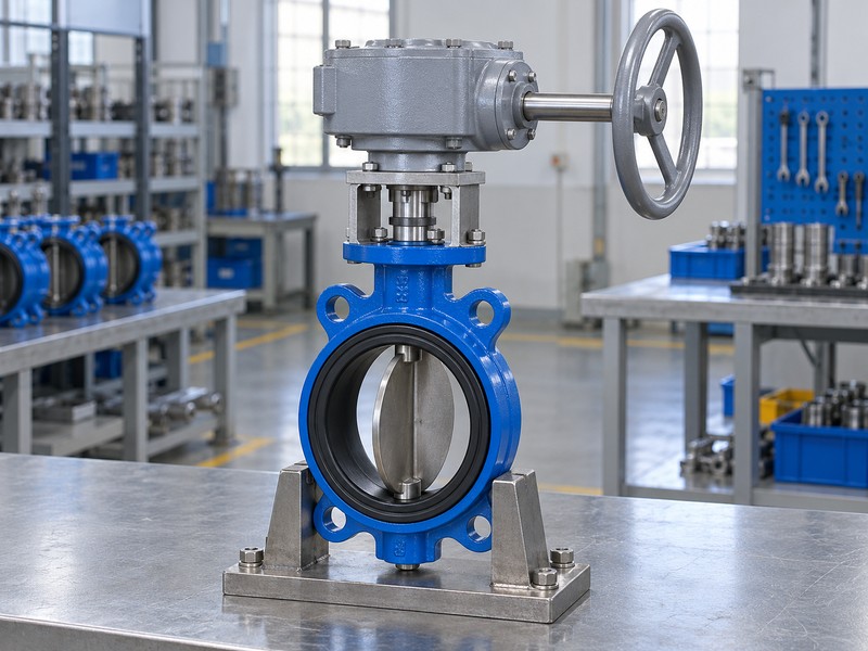
2. What axes belong on a butterfly valve gearbox drawing?
A butterfly valve gearbox drawing should distinguish the handwheel input axis, valve output axis and mounting-face datums. Record assembly orientation and the viewing direction used for rotation arrows. Pipeline face-to-face dimensions need their own references, since the valve’s top mounting datum cannot replace the dimensions that locate its body in the pipe system.
How should the reviewer follow the dimension chain?
Trace dimensions from the defined mounting face and output centreline to the actual valve shaft and operator envelope. Follow each reference. Identify where shaft projection, coupling length and bracket height enter that chain, then compare the same datums on the mating parts. A changed input reducer or mounting orientation needs review because its envelope and direction relationship may differ from the earlier assembly.
- Label input, output and mounting-face references separately.
- State the observer direction for any rotation arrow.
- Trace shaft and bracket dimensions from common datums.
Key takeaway: Use consistent datums across the valve, coupling, bracket and operator.
| Check | What you should confirm |
|---|---|
| Axes | Input and valve output are separately identified |
| Datums | Mating dimensions share defined physical references |
| Orientation | Selected mounting position matches the installation review |
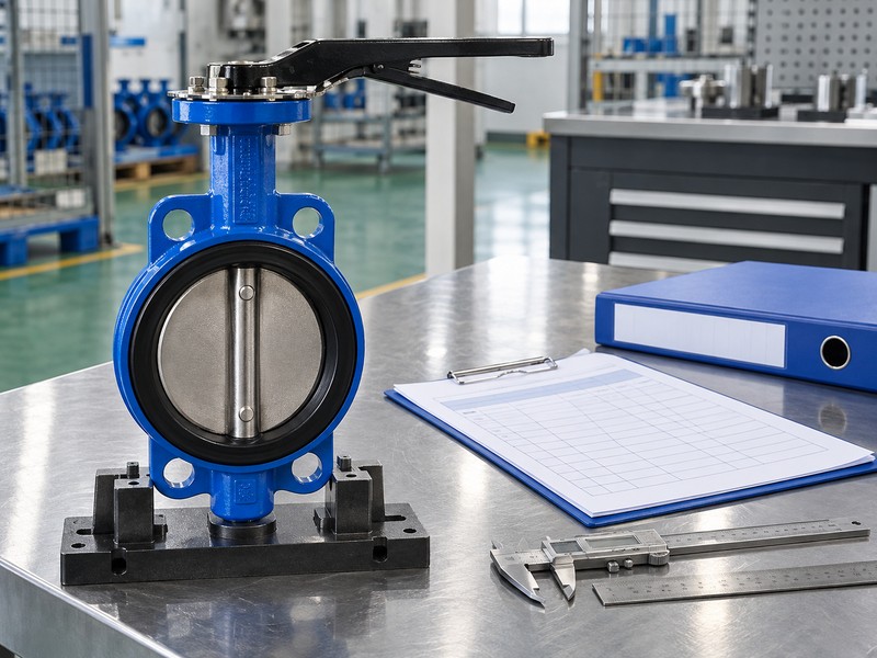
3. What standard fits a butterfly valve gearbox drawing?
A butterfly valve gearbox drawing must name the standard and edition at the interface it actually defines. ISO 5211:2026 covers part-turn actuator attachments, while ISO 5210:2026 addresses multi-turn attachments. A package can contain different interface arrangements, so one designation cannot establish the complete mounting, shaft connection or operating suitability of every component.
What does the part-turn attachment scope leave open?
The public scope of ISO 5211:2026 addresses attachment flange and driving-component dimensions with reference interface and coupling torques. Check the actual boundary. It excludes the intermediate support’s attachment to the valve, and control-valve application requires supplier-purchaser agreement. Review the selected bracket, drive detail and duty independently; a flange label cannot function as a general compatibility approval or product certification.
- Identify the standard and edition at each interface.
- Separate part-turn and multi-turn attachment requirements.
- Review support-to-valve attachment and actual duty independently.
Key takeaway: Apply each standard within scope and verify remaining interfaces and duty separately.
| Check | What you should confirm |
|---|---|
| Scope | Named standard applies to the actual interface |
| Boundary | Intermediate support attachment has its own definition |
| Approval | Complete assembly fit and duty receive separate review |
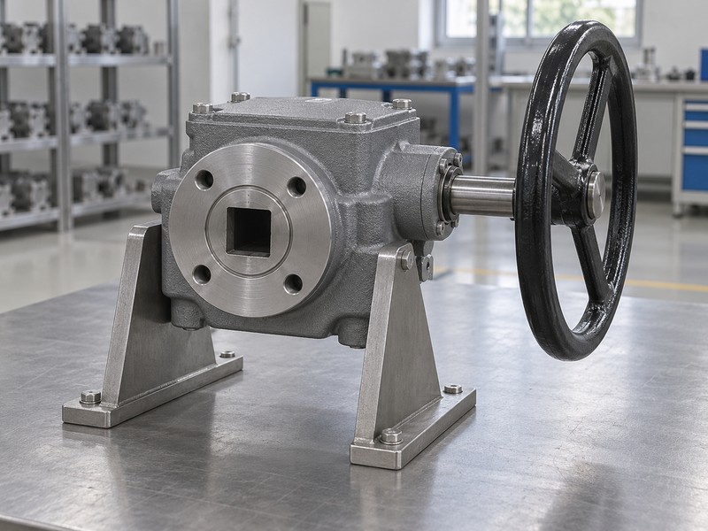
4. What mounting fits a butterfly valve gearbox drawing?
The mounting detail in a butterfly valve gearbox drawing must define the actual hole pattern, angular orientation, thread specification and seating features. Compare pitch-circle dimensions and hole locations against the same datum. A shared nominal flange designation cannot establish correct thread form, usable thread depth, spigot fit or the selected bolt arrangement.
Which details can a bolt-pattern match miss?
Review thread depth, fastener length, engagement requirements and any locating feature against the approved mating parts. Check face seating. The selected instructions should define how the interface locates and carries its loads, with tolerances and inspection characteristics recorded. Use specified dimensions; do not scale undimensioned or not-to-scale views.
- Compare hole positions and angular orientation from common datums.
- Verify actual threads, depths and fastener requirements.
- Check locating features and correct mounting-face seating.
Key takeaway: A mounting review needs the full dimensioned interface, including threads and seating features beyond the visible bolt pattern.
| Check | What you should confirm |
|---|---|
| Pattern | Hole locations and orientation match the mating detail |
| Threads | Specification, depth and engagement are defined |
| Location | Spigot and seating features have accepted tolerances |
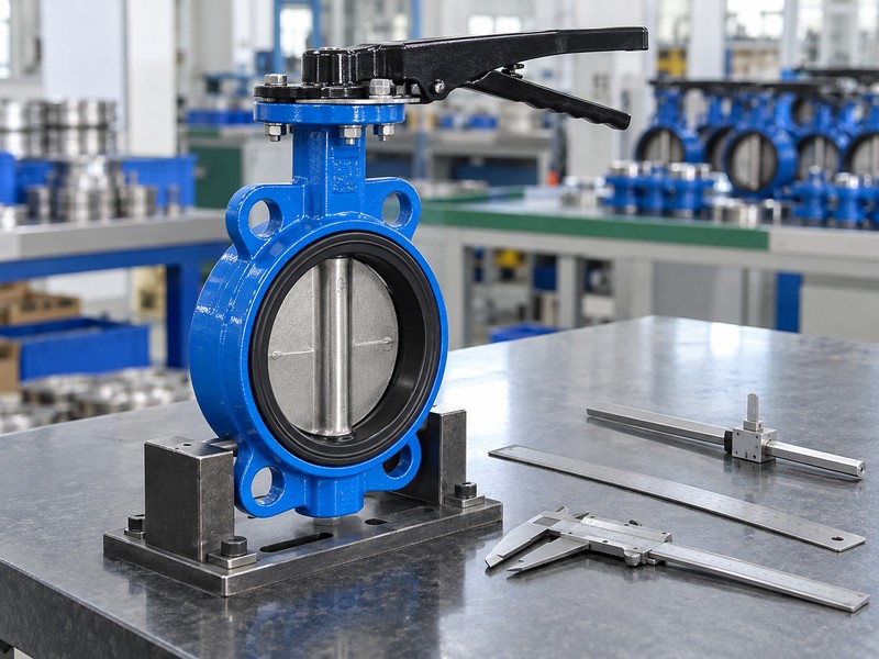
5. What drive fits a butterfly valve gearbox drawing?
A butterfly valve gearbox drawing must define the actual shaft and socket profile, orientation, tolerances and effective engagement. A square, polygonal socket or bore-and-key arrangement needs its own mating detail. Shaft projection and available axial space must permit the intended drive engagement without bottoming the connection or preventing the mounting faces from seating.
What should the coupling detail make measurable?
Identify the mating profile, key dimensions where applicable, shaft projection, socket depth and retention features. Follow the engagement chain. Compare worst permitted dimensions under the selected tolerances, with required clearance and usable contact length defined by the actual design. Your inspection plan should identify those characteristics directly; a photograph of apparently similar shafts cannot establish a fit class or accepted load-transmitting engagement.
- Match actual shaft and socket profiles and orientation.
- Review tolerances, projection and effective engagement length.
- Check retention and axial clearance against face seating.
Key takeaway: Verify mating geometry and engagement, resolving insufficient contact and axial bottoming.
| Check | What you should confirm |
|---|---|
| Profile | Actual mating geometry and tolerances are identified |
| Engagement | Usable contact length meets the accepted design |
| Axial space | Connection clears without preventing correct face seating |
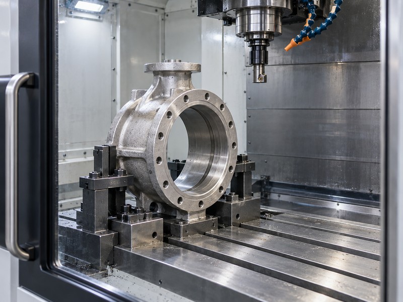
6. What turns follow a butterfly valve gearbox drawing?
A butterfly valve gearbox drawing should connect the selected input rotations with the accepted valve-shaft output travel. State the complete reduction arrangement and its ratio definition. A quarter-turn valve output cannot establish a quarter-turn handwheel input, and a published turn count needs the actual operator, accepted endpoints and any extra reduction stage identified.
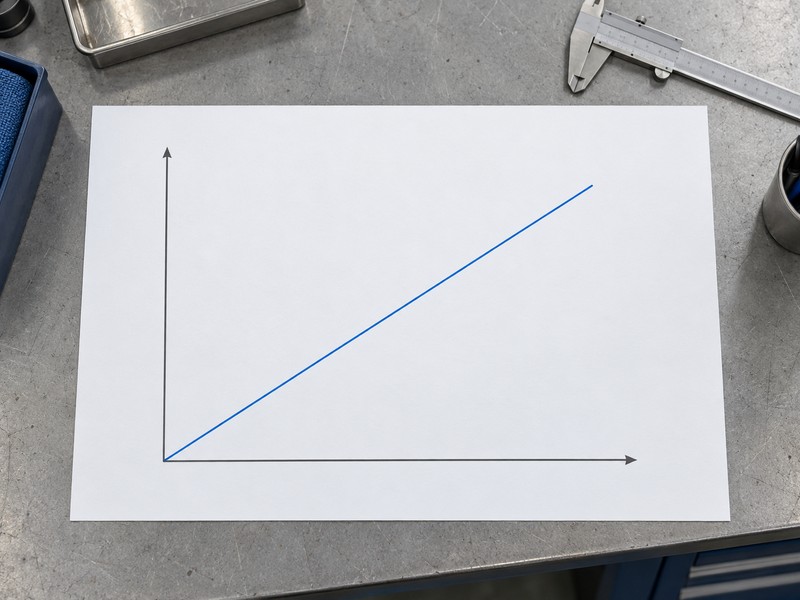
What does the straight-line motion chart represent?
The conceptual chart uses horizontal handwheel input turns and vertical shaft angle for an ideal fixed rotation ratio. Compare the selected operator data. For a defined input-to-output angular ratio i, ideal input turns equal i multiplied by output degrees divided by 360. This kinematic relationship cannot establish torque multiplication, backlash, control precision or actual endpoint settings; those need the selected assembly’s documented limits and verification.
- Identify every reduction stage and the ratio definition.
- Separate input turns from accepted output angle.
- Use selected operator data for actual travel and turns.
Key takeaway: Use actual operator documents for permitted travel and turns; the chart illustrates an ideal relationship.
| Check | What you should confirm |
|---|---|
| Input | Turns refer to the identified complete reduction arrangement |
| Output | Angle follows the valve’s accepted travel references |
| Chart | Straight line represents an ideal fixed-ratio relationship |
7. What torque supports a butterfly valve gearbox drawing?
A butterfly valve gearbox drawing needs a separate selection record for valve demand, gearbox input limits, output capacity and structural limits. Name the application point and units for every torque value. An undefined MOT or maximum output rating cannot establish operating demand, permitted input or shaft and coupling strength.
Which torque definitions should the reviewer keep separate?
Request breakaway, running and seating demand under the actual closing differential and operating duty. Trace the load path. Define MOT in the selected schedule, then distinguish operating demand from the permitted structural torque and documented rating margin. Nominal ratio alone cannot provide safe output from an input-torque figure; use actual mechanical advantage, applicable efficiency and supplier ratings, with any project selection allowance explicitly identified.
- Define torque units, application points and the MOT legend.
- Compare demand with input, output and component limits.
- Separate documented rating margin from project selection allowance.
Key takeaway: Approve the torque basis through the complete load path, with demand, capacity and structural limits distinguished.
| Check | What you should confirm |
|---|---|
| Demand | Actual valve duty establishes required operating torque |
| Capacity | Input and output limits have identified application points |
| Structure | Shaft, coupling and mounting limits receive separate checks |
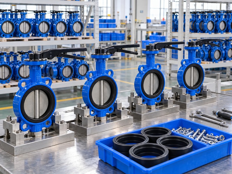
8. What space belongs on a butterfly valve gearbox drawing?
A butterfly valve gearbox drawing must show operating and maintenance space around the installed assembly. Review the wheel sweep, hand access and required cover or component withdrawal against adjacent equipment. External clearance alone cannot establish disc clearance inside the pipe, so retain the separate valve-body and pipeline references in the installation review.
What should the installed envelope include?
Compare the full valve-operator outline with the actual skid, supports, guarding and maintenance access arrangement. Check the removal path. Identify any input orientation that changes wheel access, then verify the accepted disc sweep against mating flange and pipe bores. The selected manuals govern maintenance access and physical work; an outline cannot supply a universal maintenance interval or justify an unplanned dismantling procedure.
- Review wheel sweep and operator hand access.
- Reserve the required cover and component removal space.
- Check internal disc clearance independently of external envelope.
Key takeaway: Verify operating access, maintenance withdrawal and internal disc clearance as separate requirements.
| Check | What you should confirm |
|---|---|
| Operation | Wheel and hand access fit the actual installation |
| Maintenance | Selected components have their required withdrawal space |
| Pipeline | Disc sweep clears the actual mating bore |
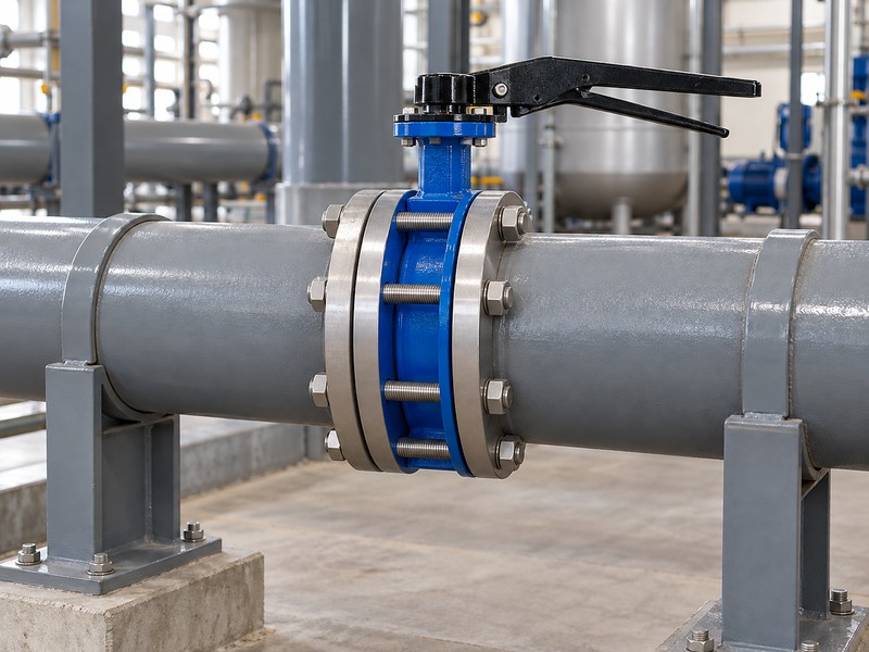
9. What loads belong on a butterfly valve gearbox drawing?
A butterfly valve gearbox drawing should identify installed package mass, centre of gravity, support arrangement and the permitted external loads. Added operators or mounting parts can change the assembly’s loading and balance. A clear dimensional outline cannot establish structural adequacy or authorize a lifting method without the applicable load data and selected handling instructions.
What evidence connects the assembly with its support?
Request the selected package mass and load application points, with moments and support conditions defined where required. Follow the support path. Review bracket and valve attachment loads separately from normal drive torque, including changes caused by reorientation or attached equipment. Any handling plan must use the approved lifting arrangements; the drawing cannot establish the handwheel or gearbox as a lifting point merely because it is accessible.
- Identify actual package mass and centre of gravity.
- Review external forces and moments at defined interfaces.
- Use selected support and approved handling information.
Key takeaway: Review structural loads and support separately from dimensional fit.
| Check | What you should confirm |
|---|---|
| Mass | Installed configuration has an identified weight basis |
| Loads | Forces, moments and application points are defined |
| Support | Selected attachments and handling arrangements have their own basis |
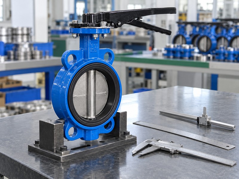
10. What releases a butterfly valve gearbox drawing?
Release a butterfly valve gearbox drawing after its interfaces, torque basis, space, support and accepted travel definition close against the required evidence. Match the pointer, coupling index, valve endpoint and approved stop arrangement. A nominal stop or a generic position image cannot establish that the actual assembly reaches its accepted endpoint or meets its separate sealing requirement.
What should remain controlled after drawing approval?
Retain the accepted general arrangement, drive detail, component list, selected manuals and inspection decisions with product identity. Review affected changes. A revised coupling, machining dimension, bracket or operator orientation needs its applicable fit, load and movement checks before release, with authorized isolation governing any physical work. Dimensional approval cannot establish self-locking, environmental protection, endurance or leakage performance; request the relevant evidence separately when the project requires those functions.
- Close dimensional, load and accepted travel requirements.
- Link inspection decisions with the controlled assembly revision.
- Review changed components and repeat affected verification.
Key takeaway: Preserve the accepted assembly baseline and repeat affected checks after changes.
| Check | What you should confirm |
|---|---|
| Baseline | Accepted drawings and component definitions match |
| Travel | Pointer, coupling and physical endpoint references agree |
| Change | Affected interfaces and functions receive renewed review |
Send RUITO your valve identification, installation envelope, operator requirements and existing interface drawings. We can review the proposed valve assembly and identify the selected operator, drive and inspection documents still needed. Contact us before approving a drawing revision or purchasing a replacement from an outline alone.
FAQ
Q1: Can a matching flange designation prove the gearbox fits?
No. Check the actual hole pattern, threads, locating features, drive profile, tolerances and engagement against the selected assembly details.
Q2: What’s the best drawing set to request?
Request the controlled assembly and drive details. Include the actual valve and operator identities, component list, selected manuals and drawing approval status.
Q3: How do I know whether the shaft engages correctly?
Review the full dimension chain. Compare profile, tolerances, projection, socket depth, usable engagement and clearance without preventing correct mounting-face seating.
Q4: Can I multiply handwheel torque by ratio to approve output?
No. Use actual mechanical advantage, applicable efficiency and supplier ratings, then check the valve, shaft, coupling and mounting limits separately.
Q5: What should I do when the schedule only says MOT?
Request its definition. Confirm units, application point, operating conditions and whether the value describes demand, a limit or another selected-document notation.