
Fix butterfly valve open and close position mistakes by comparing the disc plane with the pipe-flow axis and the selected drawing’s endpoints. In a simplified concentric valve, the open disc plane lies approximately parallel to flow and the closed plane crosses it. Shaft indexing, operator indication and inspection evidence must refer to that same identified assembly.
If a buyer treats a wide-looking opening in an angled photograph as full travel, the accepted position can start from a mistaken view. A handwheel or detached handle may add another conflicting cue. Establish a fixed pipe-axis reference, then connect the disc’s actual endpoint with the approved drawing and operator information before accepting the description.
1. What defines butterfly valve open and close position?
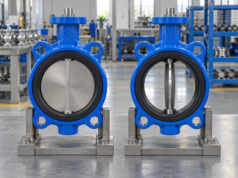
The butterfly valve open and close position reference compares the disc plane with the pipe-flow axis. A closed concentric disc presents its face across that axis; an open disc lies approximately along it. Keep the reference tied to the selected geometry, since shaft direction, flange face and viewing angle describe different things.
Which plane should you follow in the illustration?
Follow the broad disc face between the two matching concentric examples. Compare the same geometry. The closed example places that face perpendicular to flow, while the open example shows its edge with the face approximately parallel to flow. The selected drawing and endpoints define supplied valve travel; these pictures illustrate geometry.
- Identify the pipe-flow axis before comparing positions.
- Follow the disc plane rather than the shaft direction.
- Use matching geometry for open and closed references.
Key takeaway: Define each position against the disc plane and pipe axis, with the actual drawing establishing the supplied configuration.
| Check | What you should confirm |
|---|---|
| Closed | Disc plane crosses the flow axis |
| Open | Disc plane lies approximately along the flow axis |
| Reference | Actual construction and endpoints follow the selected drawing |
2. What moves in butterfly valve open and close position?
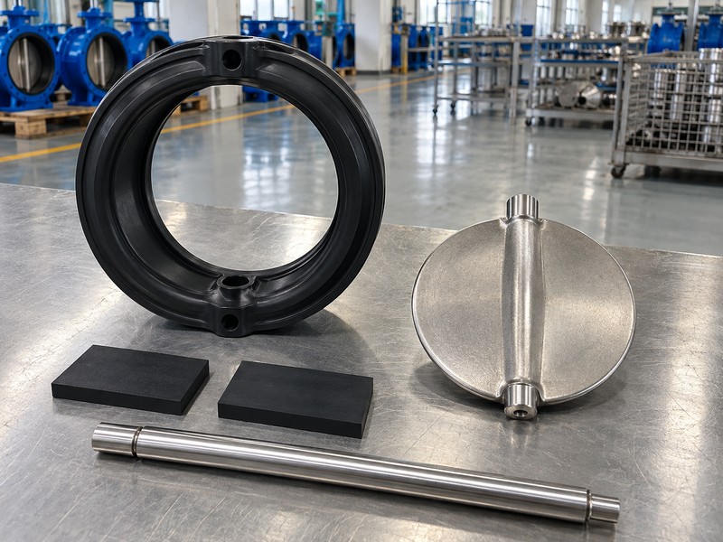
For butterfly valve open and close position, the shaft rotates the disc through its accepted travel while both remain in the valve bore. The disc changes the available passage as it turns. It does not withdraw from the pipeline like a gate, and full opening does not remove the shaft or every obstruction from the flow path.
Where does the operator’s movement reach the disc?
Trace the operator connection into the actual shaft and its disc attachment. Inspect the section drawing. The selected construction defines the coupling, retention, support and any shaft mark used as a reference. List the actual disc, shaft, seat and attachment parts before accepting external movement as an internal-position reference.
- Trace the operator, shaft and disc connection.
- Identify support and retention from the actual construction.
- Keep external movement linked to the internal closing member.
Key takeaway: The valve changes position through disc rotation, with the actual transmission establishing the relationship between external movement and internal travel.
| Check | What you should confirm |
|---|---|
| Movement | Shaft and disc follow rotary travel |
| Connection | Accepted attachment transmits the intended motion |
| Open bore | Disc and shaft still occupy part of the passage |
3. Why does viewpoint affect butterfly valve open and close position?
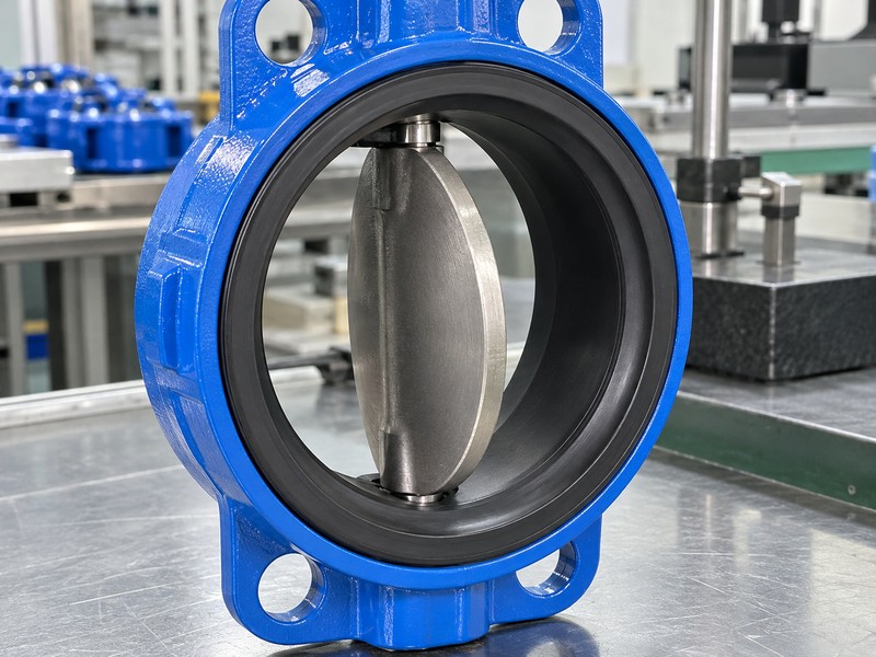
A butterfly valve open and close position comparison needs a stated viewing direction because perspective can hide the disc edge or exaggerate its visible face. Looking along the pipe axis differs from looking across it. A rotated photograph can also make handle or shaft orientation appear inconsistent without showing a real mechanical mismatch.
What should you record with a position photograph?
State the observed end, pipe-axis direction and relevant drawing reference alongside the product identity. Fix the viewpoint. Compare photographs only when their orientation and assembly are known, then use the actual section or inspection record to resolve obscured features. A clear picture can explain geometry, but it cannot establish hidden coupling engagement, applied pressure or the leakage result required for acceptance.
- State the observer direction and pipe-axis reference.
- Keep the valve orientation consistent between comparison views.
- Identify features hidden by perspective or the operator.
Key takeaway: Compare position photographs using a common, documented viewing reference.
| Check | What you should confirm |
|---|---|
| Viewpoint | Observed end and viewing direction are stated |
| Comparison | Images refer to matching orientation and geometry |
| Limits | Hidden features retain their own verification requirements |
4. What endpoints define butterfly valve open and close position?
Accepted drawing references define butterfly valve open and close position, with any angle convention stated for the actual assembly. For the simplified concentric explanation here, zero degrees means closed and ninety degrees means open. Those explanatory labels cannot set another model’s stops, establish its turning direction or replace its selected operating instructions.
How should the reviewer interpret an endpoint label?
Connect the physical disc reference with the shaft indexing and accepted travel limits. Check the chosen convention. Offset geometry, operator mounting and inspection requirements must come from the actual model documents, so a general quarter-turn description cannot supply adjustment values. Keep a pointer-to-disc discrepancy open until the accepted reference is verified.
- State the angle convention used for explanation.
- Identify physical disc references and accepted travel limits.
- Review a label-to-disc mismatch against the actual drawing.
Key takeaway: An endpoint needs its defined physical reference; a general angle label cannot establish another assembly’s travel or adjustment settings.
| Check | What you should confirm |
|---|---|
| Convention | Angle labels have a stated mechanical reference |
| Endpoint | Accepted position follows the actual model drawing |
| Mismatch | Observed disagreement remains an open inspection finding |
5. Can a lever identify butterfly valve open and close position?
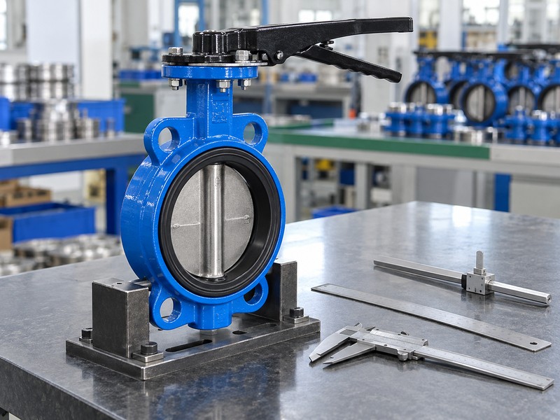
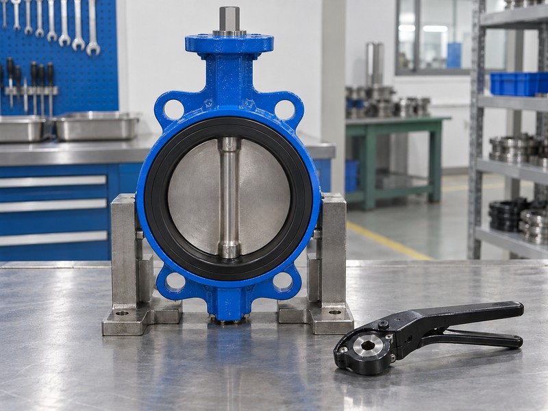
A lever can indicate butterfly valve open and close position only through its verified shaft fit, mounting and indexing relationship. Its apparent direction cannot provide a universal position rule for every assembly. A detached lever supplies even less evidence because the photograph cannot establish which shaft it fits or how it would be indexed after installation.
What can the detached-component illustration establish?
The illustration shows a separate lever and a closed concentric valve as component concepts. Check the actual fit documents. It does not identify matched parts, prove a compatible mounting hole or establish the selected open and closed indexing. Use the accepted drawing, selected instructions and identified components before approving a replacement.
- Verify actual lever and shaft component identities.
- Use the selected mounting and indexing information.
- Keep detached-part photographs separate from compatibility evidence.
Key takeaway: A lever becomes a usable position cue only after its actual fit and indexing are connected to the accepted disc reference.
| Check | What you should confirm |
|---|---|
| Fit | Actual lever and shaft interfaces match |
| Indexing | Selected assembly defines the indication relationship |
| Illustration | Detached components do not establish matched parts |
6. How does gearing affect butterfly valve open and close position?
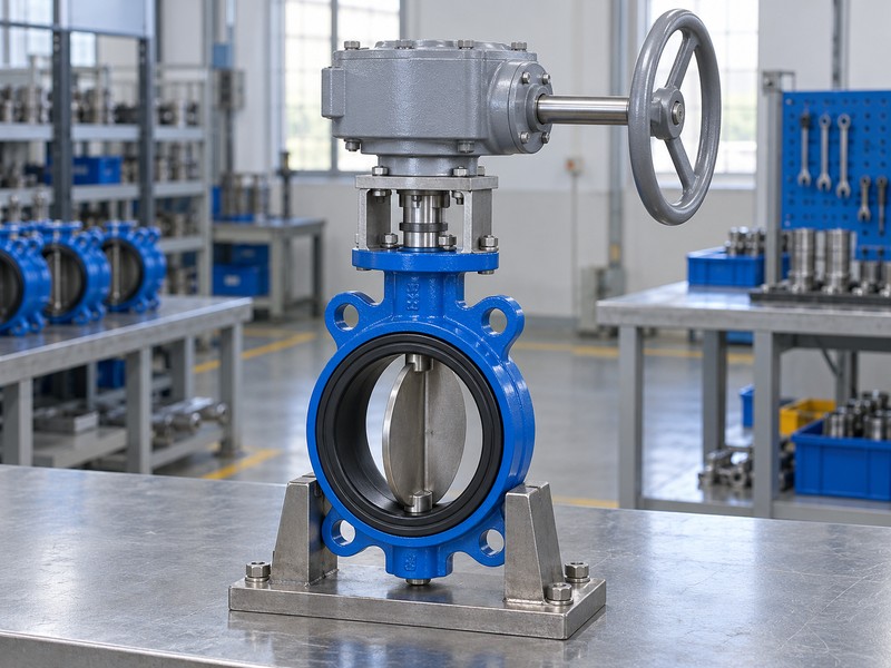
With a gearbox, butterfly valve open and close position follows the valve’s accepted shaft output while selected gearing determines the handwheel input. A quarter-turn output cannot establish a quarter-turn handwheel movement or a universal turn count. Follow the actual output coupling and indication rather than treating the wheel’s visible angle as the disc’s position.
Which operator references belong beside the valve drawing?
Identify the selected gearbox, mounting, output connection and position indicator in the assembly documents. Follow the transmission. Use its instructions for input movement, direction, travel limits and any holding claim, with the valve’s accepted endpoints retained as the physical reference. Reaching resistance at the wheel cannot diagnose closure or authorize more force, and unexplained disagreement needs review before stop settings change.
- Separate handwheel input from valve-shaft output.
- Match coupling and indication with the accepted assembly.
- Use selected operator information for gearing and limits.
Key takeaway: Use verified gearbox output indexing for position and selected gearing for input rotations.
| Check | What you should confirm |
|---|---|
| Input | Wheel rotations depend on the selected gearing |
| Output | Shaft travel follows the valve’s accepted endpoints |
| Indication | Pointer indexing matches the actual assembly definition |
7. What clearance supports butterfly valve open and close position?
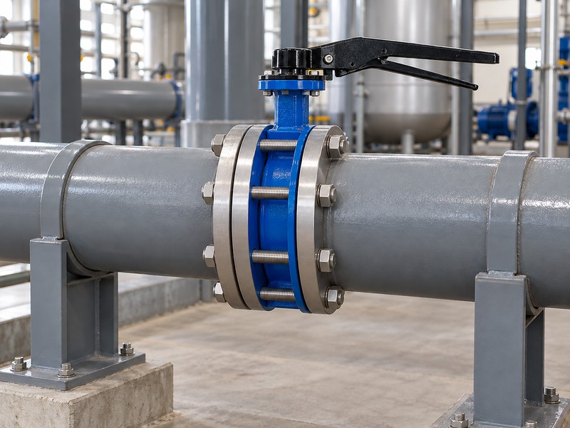
The installed butterfly valve open and close position needs sufficient clearance for the accepted disc sweep and the specified joint arrangement. Mating pipe, flange bore, lining or a reducer can affect that space. Nominal size and a familiar body shape cannot establish that the installed valve can reach its intended endpoints without contact or distortion.
What should the installation review compare?
Compare the actual valve drawing with flange, bore and support details from the installation. Follow the moving envelope. Apply the selected seat-compression and gasket instructions, then identify any interface condition that could explain restricted travel. Qualified personnel should establish isolation and permitted movement for a physical check; binding remains a finding to resolve before changing force or the accepted travel settings.
- Compare full disc sweep with the actual mating bore.
- Check joint, gasket and seat-compression requirements.
- Resolve interference through the authorized review process.
Key takeaway: Accepted endpoints require clearance for actual disc sweep under the selected installation conditions.
| Check | What you should confirm |
|---|---|
| Clearance | Disc sweep fits the actual pipe and flange bore |
| Joint | Selected installation requirements govern compression and support |
| Check | Unexplained resistance remains open for investigation |
8. What flow follows butterfly valve open and close position?
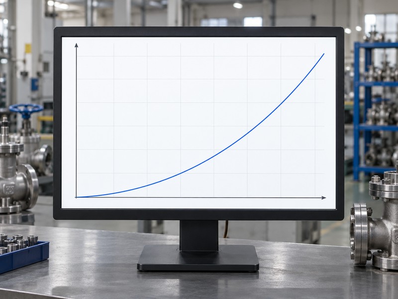
At intermediate travel, butterfly valve open and close position describes mechanical position while actual flow depends on the valve and system conditions. Half the shaft travel cannot establish half the flow. The disc and shaft remain in the open bore, so a full-open indication cannot establish zero pressure loss or an empty passage.
What does the conceptual liquid curve explain?
The curve uses horizontal liquid flow and vertical pressure loss at fixed flow coefficient and density. Review the actual operating point. Model size, opening, fluid properties and pressure conditions determine the applicable sizing data, with gas duty requiring its own inputs. Intermediate settings need a separate continuous-throttling review against the selected model’s accepted envelope.
- Separate mechanical travel from measured process flow.
- Request opening-specific model data for the actual fluid.
- Review continuous operating duty against the accepted envelope.
Key takeaway: Use the actual model and system data to evaluate flow, with position indication retained as a mechanical reference.
| Check | What you should confirm |
|---|---|
| Position | Travel identifies a mechanical opening |
| Flow | Coefficient and system conditions determine the calculation |
| Curve | Conceptual liquid relationship is not measured valve performance |
9. Does butterfly valve open and close position prove sealing?
A butterfly valve open and close position closure record must keep physical position separate from leakage acceptance and pressure direction. A disc at its accepted closed endpoint can still need a defined sealing test. Flow in either direction also cannot establish equal permitted closure differentials, particularly where the model declares directional ratings separately.
Which conditions make a closure result usable?
Identify the actual unit, medium, pressure, direction, duration and leakage criterion in the agreed test record. Review the pressure scope. A method such as ISO 5208 addresses its specified integrity and closure checks, without establishing position-control accuracy or increasing working-pressure limits. Keep shell integrity, shaft external leakage and seat closure distinguished, and use the actual model rating for each required pressure direction.
- Link leakage results with product identity and conditions.
- Identify pressure direction and its permitted closing differential.
- Separate position, shell integrity and seat acceptance.
Key takeaway: Verify position and leakage through their separate references and required evidence.
| Check | What you should confirm |
|---|---|
| Position | Disc reaches the accepted physical reference |
| Sealing | Required result states its actual test conditions |
| Direction | Closing differential fits the model’s declared scope |
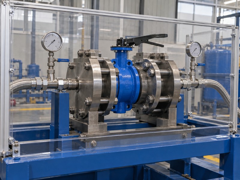
10. What records confirm butterfly valve open and close position?
A reliable butterfly valve open and close position record connects product identity, accepted geometry and observed movement under stated conditions. Preserve the drawing revision, operator definition and inspection basis with the order. A generic image, a familiar lever or a remote command cannot establish every installation, material and operating requirement for the supplied configuration.
What should the buyer retain for repeat enquiries?
RUITO links product IDs with controlled valve drawings, materials and inspection records. Check the configuration boundary. Ordinary clean-water duty uses 5–60°C and the selected PN10/16 pressure-temperature rating, while other fluids and specialized installations need their own verified scope. Keep accepted endpoints and actual drive conditions with those records, including any required product approval coverage for the exact configuration and destination.
- Retain product identity and accepted drawing revisions.
- Connect endpoints with actual operator and duty information.
- Review configuration and approval scope before repeat supply.
Key takeaway: Retain identified configurations and accepted references for repeat supply and later position checks.
| Check | What you should confirm |
|---|---|
| Identity | Records refer to the supplied configuration |
| Movement | Accepted endpoints and observed conditions are retained |
| Duty | Material, rating and required approval scope match |
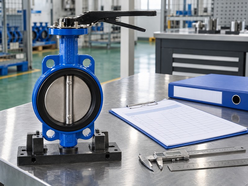
Send RUITO your valve identification, installation drawing, fluid and required operating function. We can review the proposed configuration and identify which endpoint, operator or inspection references need clarification. Contact us before approving an unresolved position description or a replacement based only on appearance.
FAQ
Q1: Can I tell the position by looking along the pipe?
Use the disc-plane reference. Confirm the viewing direction and actual drawing, since perspective and hidden features can make a photograph misleading.
Q2: What’s the difference between the shaft axis and disc plane?
They describe different references. The shaft defines rotation, while the disc plane identifies the broad face that crosses or aligns with the flow axis.
Q3: Can I assume a detached lever fits the nearby valve?
No. Check actual component identities, shaft fit and indexing through the selected assembly documents before accepting compatibility.
Q4: How do I know whether the handwheel needs several turns?
Check the selected gearing. Valve output travel and handwheel input rotation require separate references.
Q5: Can a closed position guarantee no leakage?
No. Verify the required seat-closure result under the agreed pressure, medium, direction, duration and leakage criterion.