
Fix wiring mistakes by matching your butterfly valve with tamper switch wiring diagram to the identified valve assembly and compatible panel or monitor-module manual. Read contact states, supervisory lead assignments and circuit requirements as one document set. Manufacturer diagrams show why a wire color or contact label cannot establish a universal connection.
A valve can indicate fully open while an incorrectly selected contact leaves its supervisory input in the wrong state. Copying another valve’s diagram can turn that mismatch into rework, unresolved trouble reports or a missed position change. Review the actual assembly, input circuit and required test evidence before purchasing or installation teams accept the drawing.
1. Which butterfly valve with tamper switch wiring diagram fits?
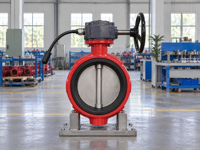
The correct butterfly valve with tamper switch wiring diagram identifies your exact valve, operator, switch arrangement and document revision. Match those identities with the order and installed labels. A catalogue image of a similar handwheel housing cannot resolve whether the assembly supervises an open position, a closed position or a different specified condition.
Which documents belong in the review package?
Check the model suffix. Request the valve-switch drawing, selected installation instructions, compatible input documentation and project point schedule. An minor model change can alter the supervised position, lead arrangement or permitted accessories, so retain the applicable parts list and approval evidence with those documents. Ask for clarification when a drawing carries several variants without identifying the supplied one.
- Match valve, operator and switch identities with actual labels.
- Record document number, revision and supplied configuration.
- Pair the switch drawing with the selected input manual.
Key takeaway: Approve an identified document package before reviewing individual connections.
| Check | What you should confirm |
|---|---|
| Assembly | Exact model and supervised position are identified |
| Revision | Drawing and supplied configuration agree |
| Interface | Selected panel or module documents accompany the drawing |
2. How does a butterfly valve with tamper switch wiring diagram work?
A butterfly valve with tamper switch wiring diagram describes electrical contacts that change with a monitored valve position. Mechanical movement operates the selected switching arrangement, and a compatible input interprets its circuit state. The handwheel or another specified operator moves the valve; adding a supervisory switch does not create a motorized valve.
What can position supervision tell the operator?
Separate the evidence. A position report concerns the monitored mechanism and its accepted relationship with valve travel. It cannot establish available water flow, an unobstructed downstream pipe or acceptable seat leakage under a closing differential. Keep hydraulic test records, mechanical travel verification and electrical supervision records distinct when your team reviews a completed assembly or investigates a disagreement between indications.
- Identify which mechanical position operates the selected contacts.
- Review position indication against accepted valve travel.
- Request hydraulic evidence separately when the project requires it.
Key takeaway: Treat a normal supervisory report as position evidence within its defined scope.
| Check | What you should confirm |
|---|---|
| Position | Switch state follows the specified mechanical condition |
| Hydraulics | Flow and leakage need their own verification |
| Operation | Valve movement comes from the selected operator |
3. Can a butterfly valve with tamper switch wiring diagram use NC?
A butterfly valve with tamper switch wiring diagram can use the designated contact only when its documented state and the selected input requirements agree. NC, NO and common labels describe contacts against a defined reference condition. Read the drawing’s position note before deciding which path represents normal service or movement away from it.
Why can a contact label conflict with the valve indication?
Read the position note. A contact symbol may describe a switch reference condition while the diagram depicts a particular valve position. The TYCO BFV-300/BFV-300C technical sheet identifies separate open-supervised and closed-supervised models, illustrating why the model and diagram caption belong in your review. Record expected continuity at the specified valve positions without assuming every tamper input requires the same contact path.
- Read NC, NO and common against the stated reference.
- Record the valve position depicted by the diagram.
- Compare expected continuity with the input’s required normal state.
Key takeaway: Resolve contact terminology through the selected diagram and its position note.
| Check | What you should confirm |
|---|---|
| Label | Contact designation has a stated reference condition |
| Position | Diagram identifies the depicted valve condition |
| Logic | Normal and changed states match the approved input design |
4. What leads fit a butterfly valve with tamper switch wiring diagram?
The leads shown on a butterfly valve with tamper switch wiring diagram must match the supplied switch arrangement and assigned function. Trace terminal or lead identifiers through the selected document instead of borrowing another manufacturer’s colors. Supervisory and auxiliary contacts may have different lead provisions and permitted uses even when both sit inside one housing.
Can the auxiliary contact replace the supervisory contact?
Keep the assigned functions. The Victaulic Series 705 technical publication assigns its S1 contact to fire-alarm supervision and distinguishes the auxiliary S2 connection. That arrangement cannot justify interchanging those functions on another assembly or treating spare leads as equivalent supervisory connections. Your review should preserve each identified function, its permitted circuit and any manufacturer restriction on panel connection.
- Trace actual lead identifiers through the matching diagram.
- Keep supervisory and auxiliary assignments distinct.
- Record unused-lead treatment from the selected instructions.
Key takeaway: Use the designated supervisory contact and retain the manufacturer’s lead arrangement.
| Check | What you should confirm |
|---|---|
| Supervisory | Designated contact serves the permitted monitored input |
| Auxiliary | Separate function follows its own connection restrictions |
| Identification | Colors and terminal labels match the supplied assembly |
5. Can a butterfly valve with tamper switch wiring diagram show power?
Component power requirements on a butterfly valve with tamper switch wiring diagram come from the selected equipment manuals. A contact voltage or current rating describes a switching limit under stated conditions; it does not establish a required supply. Do not turn an AC contact rating into instructions for energizing a fire-alarm input.
How should the reviewer check the panel interface?
Separate the two circuits. A compatible module connects to the panel signaling line circuit (SLC); valve dry contacts connect to its separate specified monitored input or initiating device circuit (IDC). Ordinary valve contacts do not connect directly across SLC. Read the selected module and panel manuals for compatibility, circuit limits and required termination before approving those interfaces.
- Distinguish contact ratings from required operating supplies.
- Identify the actual conventional input or addressable module.
- Review auxiliary power and loads as separate circuit requirements.
Key takeaway: Approve electrical compatibility from the selected circuit documents rather than a familiar voltage.
| Check | What you should confirm |
|---|---|
| Rating | Contact limits suit the specified connected circuit |
| Input | Actual panel or compatible module governs the interface |
| Supply | Power requirements come from selected component documents |
6. Which EOL fits a butterfly valve with tamper switch wiring diagram?
Any end-of-line arrangement on a butterfly valve with tamper switch wiring diagram must follow the selected input’s specified topology, component value and location. An EOL symbol alone cannot define circuit supervision. Review the complete path between the module, field contacts and required termination, including any permitted continuation toward another device.
What does the module need to distinguish circuit states?
Trace the complete path. The chosen input documentation defines how normal operation, contact activation and specified circuit faults affect reporting. A resistor placed near the panel can leave a field segment outside the intended supervision, depending on the actual topology. Have the system designer identify the termination location and expected state responses; avoid assuming every short or break produces the same event on every module.
- Use the selected module’s EOL value and topology.
- Locate termination on the approved field-circuit drawing.
- Document activation and fault responses for that input.
Key takeaway: Review EOL value, location and reporting behavior as one circuit design.
| Check | What you should confirm |
|---|---|
| Value | Specified EOL component matches the selected input |
| Location | Approved termination preserves intended field supervision |
| Response | Expected circuit-state reports follow the module documentation |
7. What protects a butterfly valve with tamper switch wiring diagram?
A butterfly valve with tamper switch wiring diagram needs installation details that preserve the selected enclosure, cable entries and circuit requirements. Check the actual environment, route and connection method against applicable instructions. A weather-resistant operator housing cannot establish protection for an open entry, unsuitable gland or junction box outside its specified conditions.
Which physical details can a schematic leave unresolved?
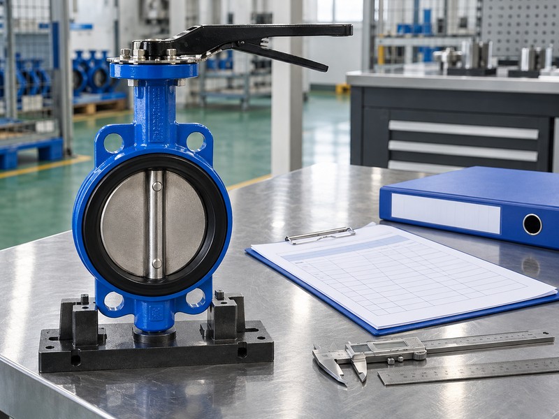
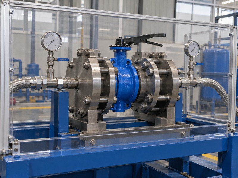
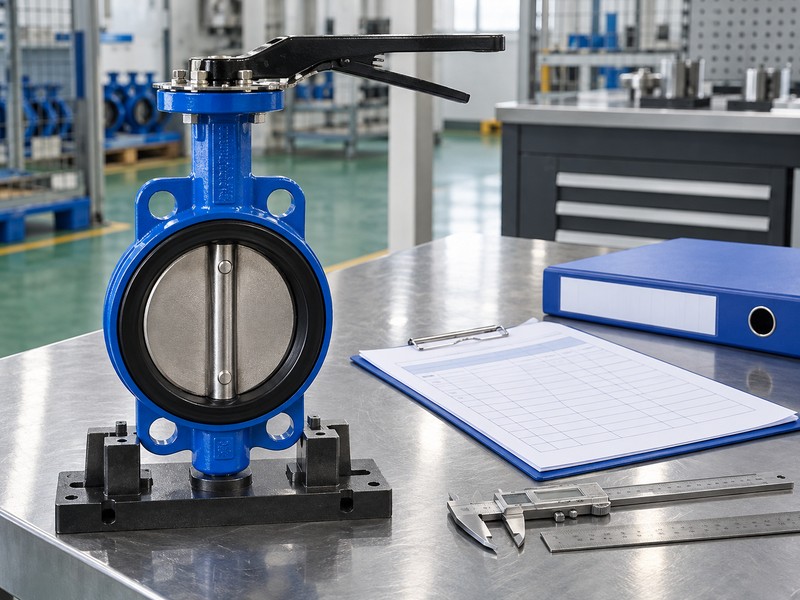
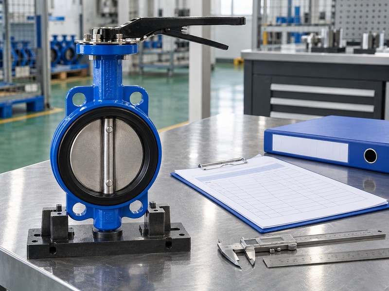
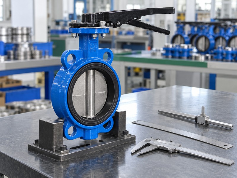
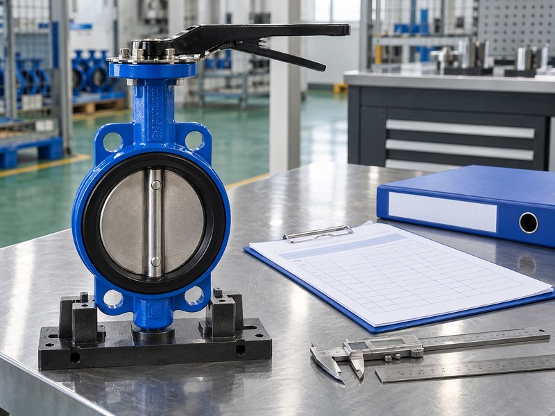
Check each entry. Review conduit or cable fittings, connection enclosures, grounding provisions and access for inspection against the selected assembly. Cable size, permitted length, segregation and shielding requirements depend on the circuit documents and applicable installation rules. The generic valve photographs show external assemblies only; enclosed contacts, internal lead routing and environmental compliance require actual product documents and inspection evidence.
- Match cable entries and fittings with environmental requirements.
- Review grounding and cable routing from applicable documents.
- Reserve access for inspection without stressing field leads.
Key takeaway: A schematic needs physical installation details before it can support an installation review.
| Check | What you should confirm |
|---|---|
| Environment | Selected enclosure and entries suit actual exposure |
| Cable | Route and electrical limits match the circuit design |
| Access | Connections remain inspectable under the approved arrangement |

8. How to test a butterfly valve with tamper switch wiring diagram?
Test a butterfly valve with tamper switch wiring diagram through an authorized commissioning plan that compares physical position, contact behavior and system reporting. Define expected results before moving the valve or disturbing a circuit. The project team must coordinate any fire-protection impairment and notifications through its approved procedure before physical testing begins.
What should the acceptance record capture?
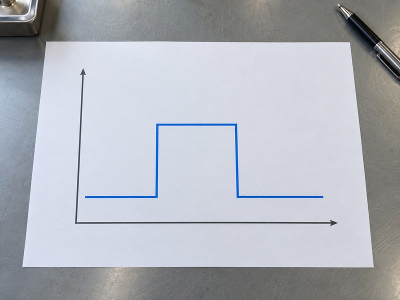
Compare the recorded states. Retain the initial position, required departure response and restored condition with the corresponding point reports. Record applicable acceptance limits from selected product documents and approved project requirements, since a generic trip angle, handwheel count or elapsed time cannot establish compliance. The conceptual chart illustrates state changes only; its spacing supplies no timing, travel or signal-voltage criterion.
- Identify the valve, input address and expected point text.
- Record required position-change and authorized fault-test results.
- Confirm restoration of the required physical and reported states.
Key takeaway: Accept documented physical and electrical results against the project’s defined criteria.
| Check | What you should confirm |
|---|---|
| Initial | Required valve position and normal report agree |
| Changed | Specified departure produces the required point response |
| Restored | Valve position and system report return as required |
9. Why can a butterfly valve with tamper switch wiring diagram fail?
A butterfly valve with tamper switch wiring diagram can fail its review when mechanical position, selected contacts, circuit installation or input configuration disagree. Start with the observed symptom and compare it against the approved state table. A normal display at rest cannot demonstrate that movement or a specified wiring fault will report correctly.
How can the team narrow an unresolved report?
Compare before changing. For a persistent off-normal report, review documented valve position, contact identity, EOL arrangement and input configuration under the authorized diagnostic procedure. If a contact changes correctly while reporting remains wrong, the investigation must include the downstream circuit and system configuration. Record findings before replacing parts, and use approved replacement instructions when the identified defect involves the operator or switch assembly.
- Record symptoms against expected physical and electrical states.
- Compare contact evidence with the corresponding system report.
- Retest affected functions after an approved correction.
Key takeaway: Locate the disagreement before treating the valve or panel as defective.
| Check | What you should confirm |
|---|---|
| Position | Actual mechanism agrees with the required reference |
| Circuit | Contact assignment and termination match approved documents |
| Reporting | Point configuration interprets the selected input correctly |
10. Who signs a butterfly valve with tamper switch wiring diagram?
The responsible project parties approve a butterfly valve with tamper switch wiring diagram against the selected products, applicable requirements and accepted system design. Identify the adopted code editions, authority requirements and approval roles in the submittal. A manufacturer drawing cannot establish universal code equivalence, project acceptance or an inspection frequency for every installation.
What should procurement and maintenance retain?
Keep the accepted baseline. Retain as-built circuit details, selected manuals, product identities, point schedules and commissioning results for later inspection and replacement review. The owner and responsible service team should derive inspection, testing and maintenance tasks from applicable requirements and selected instructions. RUITO can review an identified valve-assembly request and its documents; the project’s responsible professionals handle fire-alarm design, commissioning and acceptance.
- Verify fire-service approvals for the exact requested model.
- Retain accepted drawings and results with product identity.
- Review substitutions and repeat affected checks before acceptance.
Key takeaway: Keep product suitability, system approval and ongoing maintenance responsibilities explicit.
| Check | What you should confirm |
|---|---|
| Approval | Exact product and project requirements have identified evidence |
| Handover | Accepted documents match the installed configuration |
| Upkeep | Assigned tasks follow applicable requirements and instructions |
Send RUITO your identified valve-assembly request, connection requirements, installation conditions and existing drawings. We can review the requested configuration and identify the valve documents needed for your project review. Contact us with the exact model and destination requirements so your team can resolve product questions before purchasing or approving a replacement.
FAQ
Q1: Can I use wire colors from another valve?
No. Use the supplied assembly’s lead identifiers and matching diagram; colors and supervisory assignments vary between products.
Q2: What’s the best way to choose the EOL resistor?
Use the selected input manual. Its required component value, topology and termination location govern the approved circuit.
Q3: How do I know if the drawing shows an open valve?
Read its position note. Match that reference with the exact model and documented contact states before interpreting NC or NO.
Q4: Can I apply supply voltage from the switch rating?
No. A contact rating sets a switching limit; supply requirements come from the actual input and connected equipment documents.
Q5: How do I know if position supervision proves water flow?
It doesn’t prove flow. The position report concerns the monitored mechanism; water delivery and leakage require separate verification.