
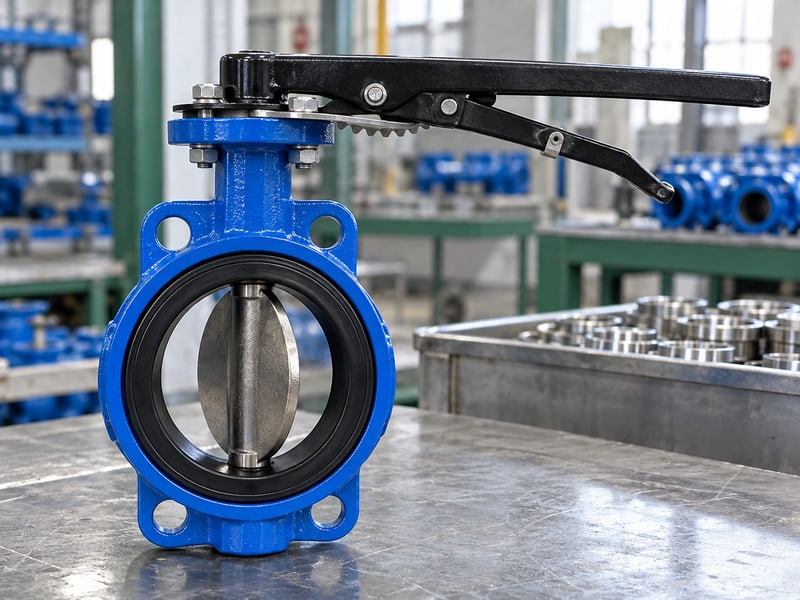
Fix butterfly valve handle orientation mistakes by verifying the disc reference, matching the drive index, and correcting the indication through an approved procedure. A replacement handle can look closed while its disc remains open. Use the model's installation, operation and maintenance instructions and accepted mounting drawing before changing hardware.
1. What does butterfly valve handle orientation show?
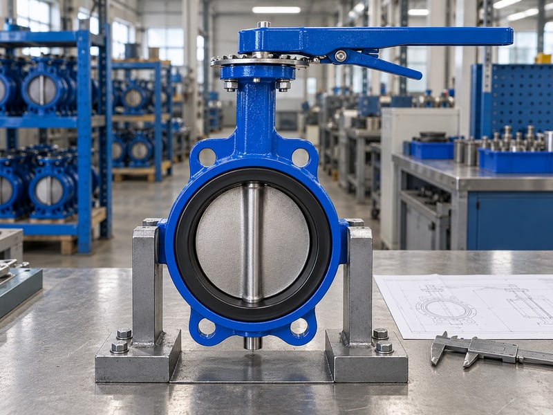
Butterfly valve handle orientation shows an external indication of disc position when the drive connection and indexing are correct. A directly mounted handle rotates a shaft, which rotates the disc inside the pipe. The position plate describes that relationship only if its mounting, stops, and markings match the assembled valve.
Which parts carry the position reference?
Trace the mechanical connection. Follow the handle hub, shaft drive, and approved position marks in the model drawing. A loose hub or incorrectly fitted adapter can break the relationship between a visible handle and an internal disc without changing the valve body's appearance.
- Identify whether the operator is a direct handle or a gearbox.
- Read the valve tag and use the matching document revision.
- Compare hub engagement and external marks with the accepted drawing.
What should the operating team retain?
Key takeaway: A useful indication belongs to a complete, verified assembly. Your records should identify the valve, operator arrangement, and reference used so another shift can read its position consistently.
| Visible item | What it establishes |
|---|---|
| Handle angle | Indicated position |
| Verified drive | Link with the disc |
| Valve tag | Applicable instructions |
Record the approved reference photograph. Include enough surrounding pipework to make its direction clear.
2. Is butterfly valve handle orientation parallel when open?

Butterfly valve handle orientation commonly places a direct handle parallel with the pipe when open, but that convention applies only after drive indexing has been verified. A bent handle, offset bracket, or approved alternative mounting may look different. Use the documented disc reference rather than transferring a familiar rule from another valve.
How do you confirm the convention?
Compare both end positions. Check the open and closed arrangements against the model's instructions and accepted general arrangement drawing. Where inspection of the disc is needed, arrange an isolated, depressurized, drained, and otherwise safe condition under the site's maintenance procedure before opening the system.
- Establish the pipe axis from the actual line being controlled.
- Identify the approved open mark and travel stop.
- Confirm that the documented shaft feature corresponds with disc angle.
How should unusual layouts be labelled?
Key takeaway: Parallel means open only for an assembly whose reference has been checked. If the approved arrangement differs, install a clear local label and train operators using that valve's reference.
| Handle appearance | Appropriate reading |
|---|---|
| Parallel, verified index | Open indication |
| Perpendicular, verified index | Closed indication |
| Unverified replacement | Position uncertain |
Resolve uncertain indexing before relying on the handle. Ask for the relevant assembly drawing if the documents omit that detail.
3. Can butterfly valve handle orientation prove closure?

Butterfly valve handle orientation cannot by itself prove tight closure or a safe maintenance boundary. The handle can reach a marked endpoint while seat damage, debris, or incomplete disc travel allows leakage. A position indication and a verified isolation condition answer different operating questions.
What evidence belongs in an isolation check?
Follow the isolation procedure. Use the site's approved method for securing energy sources, controlling trapped pressure, and checking the work boundary. A gauge reading alone may reflect a blocked connection or temporary pressure condition, so the procedure must define how its instruments and observations are verified.
- Check that the correct valve controls the intended equipment.
- Confirm the documented closed position without excessive force.
- Apply required independent isolation and pressure verification measures.
What should a closed mark mean?
Key takeaway: A closed mark communicates mechanical position, while leakage acceptance depends on the valve and test conditions. Never extend a marked position into permission for opening pipework without completing the required isolation checks.
| Check | Question answered |
|---|---|
| Position reference | Has the drive reached closure? |
| Leakage verification | Does the valve seal as required? |
| Isolation procedure | May this work proceed? |
Keep those results separately identifiable. Escalate any conflict before issuing a maintenance release.
4. How can butterfly valve handle orientation mislead you?
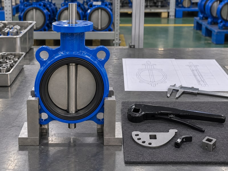
Butterfly valve handle orientation can mislead you when the visible operator loses its confirmed relationship with the disc. A handle installed on the wrong drive face may shift its indication, while looseness can add lost motion. Painted arrows and handwritten labels may also survive an earlier operator change and describe an obsolete assembly.
Which signs call for investigation?
Check changes against records. Compare today's arrangement with the accepted drawing and the most recent verified photograph. A mismatch does not identify the failed part by itself, but it gives maintenance staff a specific starting point without requiring an exploratory turn on a live process.
- Movement of the handle without corresponding shaft movement.
- A changed hub height, adapter, or position plate.
- Marks that disagree at one endpoint or throughout travel.
How should you report a discrepancy?
Key takeaway: Treat conflicting indications as an unresolved valve condition. Report what you can observe, including which parts move together and which marks disagree, rather than declaring the internal position from appearance alone.
| Observation | Investigation focus |
|---|---|
| Hub slips | Drive engagement and retention |
| Marks shifted | Indexing and plate mounting |
| Endpoint incomplete | Obstruction, stops, or assembly |
Tag the discrepancy under your site procedure. Arrange a controlled inspection with the responsible maintenance team.
5. How do you verify butterfly valve handle orientation?
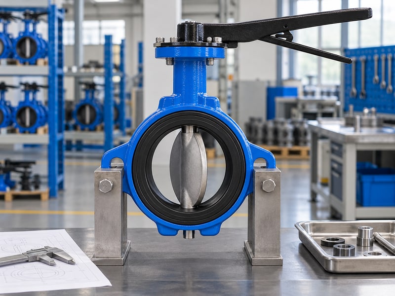
Butterfly valve handle orientation should be verified by matching the external reference to the documented shaft and disc relationship under controlled conditions. Begin with identification and records, then choose a check suitable for the valve's service. Turning a suspect handle on an operating line can change process conditions before you have established its position.
What is a controlled verification sequence?
Plan the check before movement. Confirm who authorizes operation and whether moving the valve could interrupt cooling, release stored pressure, or connect separate process sections. Direct disc inspection, hardware adjustment, and operator removal require isolation, depressurization, and any draining or decontamination specified for that work.
- Match tag, size, and operator arrangement with the instructions.
- Compare approved handle, plate, and shaft references.
- Perform authorized travel checks within documented operating limits.
What makes the result repeatable?
Key takeaway: A verification record should state its method and limits. Include both end positions and any remaining uncertainty so your team does not mistake a visual check for a leakage test.
| Record item | Useful detail |
|---|---|
| Reference | Drawing and instruction revisions |
| Condition | Isolation or authorized operating status |
| Result | Observed endpoints and exceptions |
Have the responsible person review unresolved findings. Retain the approved result beside the valve's maintenance record.
6. Can you change butterfly valve handle orientation?
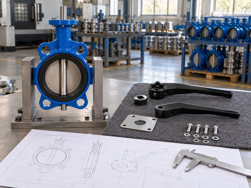
Butterfly valve handle orientation can be changed only where the valve's approved operator arrangement permits it and the disc reference remains correct. Repositioning a handle for access may require a different plate, adapter, or operator. Rotating a component until it clears nearby steelwork can leave the markings and travel limits wrong.
What must be checked before modification?
Use the accepted mounting arrangement. Request the manufacturer's instructions for that exact change and verify the shaft engagement, retention method, and stop relationship. For compact wafer butterfly valves, a short body does not reduce the space needed for handle movement or safe maintenance access.
- Establish isolation before loosening or removing operator hardware.
- Confirm permitted mounting positions and replacement components.
- Review the full stroke, labels, and access after reassembly.
How do you accept the revised arrangement?
Key takeaway: A mounting change needs a checked disc reference and updated documentation. Reverify the permitted endpoints under the approved procedure and replace labels that no longer describe the assembly.
| Proposed change | Required review |
|---|---|
| Handle repositioning | Drive indexing and plate relationship |
| New adapter | Engagement and load capacity |
| Different operator | Torque, stops, and mounting |
Obtain an updated drawing for the accepted configuration. Record the change before returning the valve to service.
7. What preserves butterfly valve handle orientation after repair?
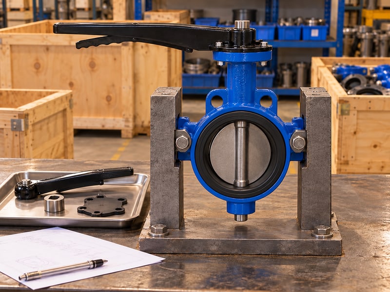
Butterfly valve handle orientation remains dependable after replacement when the new handle assembly matches the approved drive, plate, and operating limits. A hub that slides onto a shaft can still have the wrong engagement depth or angular reference. Order by valve identity and confirmed assembly requirements rather than visual similarity.
Which information supports a correct replacement?
Specify the complete interface. Provide photographs, existing markings, shaft dimensions where safely available, and the relevant drawing. A threaded body connection on a lug butterfly valve identifies its pipe mounting style; it does not establish interchangeability of handles across manufacturers or sizes.
- Match drive shape, engagement length, and retention hardware.
- Check plate mounting and approved endpoint positions.
- Confirm handle length, load rating, and locking arrangement.
What should happen after fitting?
Key takeaway: Replacement is complete when the assembled indication has been checked against disc position. Use the model-specific fastening instructions and authorized functional checks, then retain the replacement identification with the maintenance entry.
| Replacement feature | Reason for checking |
|---|---|
| Hub fit | Transmits torque without slipping |
| Plate position | Preserves readable endpoints |
| Retention | Holds the assembly in position |
Reject undocumented substitutions. Ask for a confirmed replacement arrangement when any interface detail remains unclear.
8. Why can butterfly valve handle orientation miss its endpoint?

Butterfly valve handle orientation can fall short of its expected endpoint when the drive meets an obstruction, an incorrect travel limit, or excessive operating resistance. Nearby pipework can block the handle while debris or installation interference blocks the disc internally. The visible endpoint alone cannot distinguish those causes.
What can you check without forcing the valve?
Separate external contact from internal resistance. Observe whether the handle or lock touches surrounding equipment before the intended stop. Record where resistance begins and whether it changes with operating conditions, without repeated forced attempts that could damage the shaft, seat, or drive.
- Look for a blocked sweep path and damaged locking parts.
- Compare travel stops with documented settings.
- Report unusual resistance, noise, or movement at the hub.
How should maintenance investigate further?
Key takeaway: An incomplete stroke requires diagnosis before adjustment. Maintenance staff should establish safe isolation before opening the line or changing hardware and check installation clearance using the valve's approved procedure.
| Symptom | Possible review area |
|---|---|
| Visible handle contact | External clearance |
| Early mechanical stop | Plate or stop setting |
| Rising operating effort | Service load or internal condition |
Pause attempts beyond the approved operating limit. Give maintenance staff the observed angle and operating conditions.
9. Does butterfly valve handle orientation show flow rate?
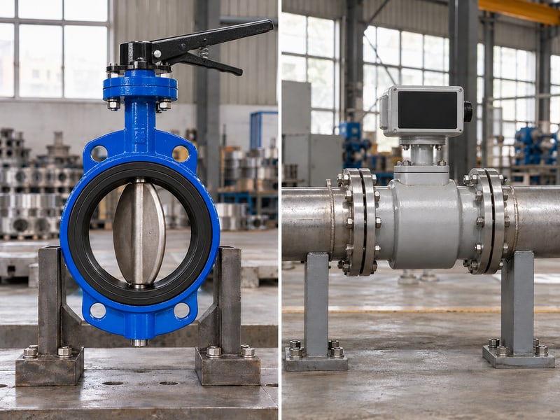
Butterfly valve handle orientation indicates a mechanical setting, not a measured flow rate. Flow through a partly open disc depends on its geometry, fluid properties, and pressure difference. A halfway handle position does not establish half of the system's full-open flow.
How should intermediate settings be used?
Check the intended valve duty. Confirm whether the selected assembly permits the proposed regulating service and operating range. In flanged butterfly valve selections, body connection and disc design are separate choices, so one configuration's flow or torque information cannot be transferred to another.
- Use the model's flow information for sizing or control review.
- Confirm actual performance with appropriate system measurements.
- Check whether the locking arrangement suits the expected loads.
What should a position label communicate?
Key takeaway: Label intermediate positions as settings unless a defined operating check supports another meaning. Keep the measured flow, pressure conditions, and valve setting together when documenting a commissioned adjustment.
| Information | Meaning |
|---|---|
| Handle position | Disc setting after verified indexing |
| Flow reading | Measured system response |
| Rated operating range | Permitted use of that assembly |
Review an intermediate setting before changing system duty. Seek operating data for the exact configuration when designing regulation.
10. What butterfly valve handle orientation details should you send?
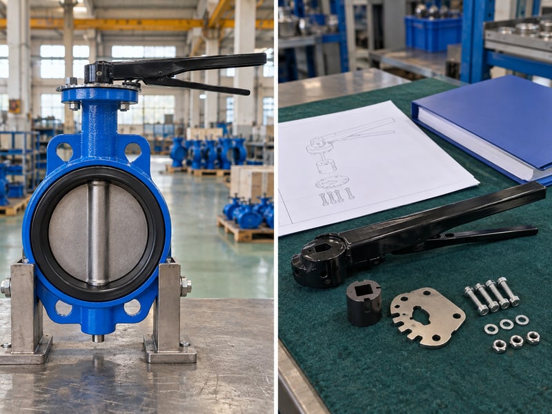
Butterfly valve handle orientation questions are easier to resolve when your inquiry identifies the valve, current mounting, operating conditions, and required indication. A clear photograph helps explain an access problem, but it cannot replace drive dimensions or an approved disc reference. Include what changed and what your team has already verified.
What makes an inquiry actionable?
Send the assembly details together. RUITO can review valve selection, operator interfaces, and the documentation needed for an agreed configuration. Provide the maximum closing differential and operating conditions if the request involves a new manual operator, since appearance alone does not establish its torque suitability.
- Valve identification, size, connection, and available drawings.
- Photos of the handle, hub, plate, tag, and surrounding pipework.
- Required access, locking function, and observed position discrepancy.
What should you request from the review?
Key takeaway: Ask for an agreed mounting arrangement and its verification requirements. For help with handle selection, indexing references, or replacement documentation, contact us today with the assembly information and your operating limits.
| Your input | Requested output |
|---|---|
| Existing interface | Compatibility confirmation |
| Operating conditions | Operator selection basis |
| Required mounting | Accepted drawing and checks |
Collect the valve details before ordering parts. Identify any observation your team could not verify safely.
FAQ
Q1: Can I assume a parallel handle means the valve is open?
Only after checking its indexing. Parallel is a common direct-handle convention, but replacement hubs and approved alternative mountings can change the visible reference.
Q2: How do I know if a closed handle means safe isolation?
Complete your site's isolation procedure. A closed indication cannot establish seat tightness, trapped-pressure control, or permission to open equipment.
Q3: Can I turn the handle around for better access?
Only with an approved arrangement. Isolate before hardware adjustments and confirm drive engagement, plate position, stops, and indication after the change.
Q4: What's the best way to identify a replacement handle?
Use the valve identity and accepted assembly drawing. Include the shaft interface and position plate because nominal size alone does not establish compatibility.
Q5: Does a gearbox handwheel angle show disc position?
No. Read the verified gearbox position indicator; wheel rotation passes through gearing, so the wheel's angular position does not directly show disc angle.