
Order butterfly valve gearbox parts from the identified operator assembly and its controlled parts list. A housing, handwheel, input transmission, output drive, bearings, seals and indication features can belong to different arrangements. A photograph alone cannot establish which replacement fits your installed unit.
Your stores team receives a replacement shaft seal with the right outside diameter, yet its material or lip arrangement differs from the removed part. A similar-looking handwheel can also have a different hub connection. Identify the assembly and part revision before purchasing turns a visual match into a replacement decision.
1. What identifies butterfly valve gearbox parts?
Identify butterfly valve gearbox parts through the operator make, model, configuration and assembly revision before choosing individual items. The valve tag helps locate the installed package, while the operator identity locates its transmission and parts definition. Record any previous coupling changes, machining or bracket substitutions that may have changed the original assembly.
Which records should accompany the enquiry?
Build a usable identification set. Include clear exterior photographs, the operator nameplate information, the accepted assembly drawing and any available illustrated parts list. Mark the required item on that list and state quantity, observed condition and service environment. RUITO valve records can help identify a supplied assembly, while internal operator spares still need the selected gearbox supplier part definition and availability confirmation.
- Record valve and operator identities separately.
- Mark the required item on the correct parts list.
- Include known modifications and the actual service environment.
Key takeaway: Give purchasing a traceable part request tied to the installed operator configuration.
| Check | What you should confirm |
|---|---|
| Assembly | Operator identity and configuration are established |
| Item | Part position and revision have a common reference |
| History | Previous substitutions or machining are recorded |
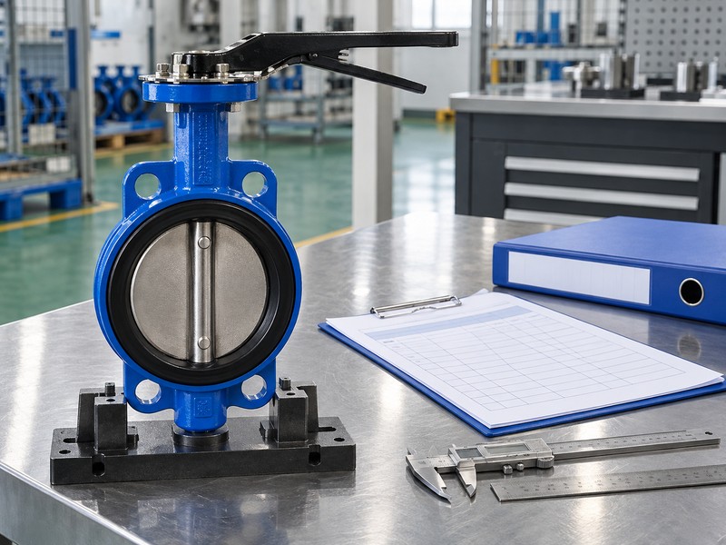
2. What housing encloses butterfly valve gearbox parts?
The housing around butterfly valve gearbox parts supports the internal mechanism and defines external mounting and cover interfaces. Material, coating, cover geometry and sealing details can differ between visually similar units. A replacement cover or housing needs the actual mating definition and repair policy rather than a guess based on casting colour.
What should the external review record?
Look for location and context. Photograph cracks, corrosion, impact marks or wet areas without treating every damp surface as proof of one failed seal. Record which face or joint shows the condition and whether nearby pipework or another component could be the source. Opening or repairing a housing belongs to the selected maintenance procedure after the required isolation and support arrangements are established.
- Identify housing and cover revisions from the parts record.
- Record damage and wet areas at their actual locations.
- Use the selected repair policy for structural damage.
Key takeaway: Keep housing identification, observed condition and repair authorization together in the spare-parts enquiry.
| Check | What you should confirm |
|---|---|
| Housing | Material and mounting arrangement match the assembly |
| Cover | Mating face and sealing definition are identified |
| Condition | Observed damage has clear location photographs |
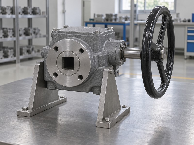
3. What transmission joins butterfly valve gearbox parts?
The transmission within butterfly valve gearbox parts connects input rotation with the valve output through the selected reduction arrangement. Worm and wheel assemblies are common, but the actual operator may include extra reduction stages or another mechanism. Match internal items by the approved parts definition, including any specified paired or complete assembly supply.
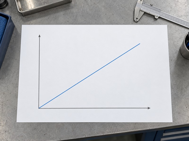
What does the motion chart explain?
Use the chart for motion only. Its straight line represents an ideal fixed ratio between input turns and output angle, without showing tooth form, gear material or real backlash. For a defined input-to-output angular ratio i, ideal turns equal i times output degrees divided by 360. That relationship cannot identify a replacement worm or wheel, establish load capacity or prove that two loose gears form an accepted pair.
- Identify the actual transmission arrangement and stages.
- Request matched or complete assemblies when specified.
- Keep ratio information separate from tooth and material definitions.
Key takeaway: Use the parts list to identify gears and the ratio schedule to understand motion.
| Check | What you should confirm |
|---|---|
| Mechanism | Selected parts record identifies the reduction arrangement |
| Motion | Chart explains ideal input and output rotation |
| Replacement | Approved item definition governs gear compatibility |
4. What input items join butterfly valve gearbox parts?
The input side of butterfly valve gearbox parts can include the handwheel, input shaft, bearings, retention items and any fitted reducer. Handwheel diameter and hub connection both need identification. A larger wheel changes the force-to-input-torque relationship and the operating envelope, so it is a configuration change that needs review.
Which hub details need confirmation?
Check the connection definition. Record the actual bore or drive profile, retention method and mating shaft detail from the selected documents. A wheel that slips onto a shaft may still lack correct engagement or retention, while an oversized wheel can permit excessive input torque. Keep any replacement handle, chainwheel or input accessory within the operator supplier limits and the accepted installation access arrangement.
- Identify wheel diameter, hub drive and retention.
- Review input accessories against the selected operator limits.
- Check the replacement wheel sweep and hand access.
Key takeaway: Replace input items against the actual connection and permitted operator input conditions.
| Check | What you should confirm |
|---|---|
| Wheel | Diameter and hub belong to the selected configuration |
| Shaft | Actual input connection and retention are defined |
| Access | Replacement fits the installed operating space |
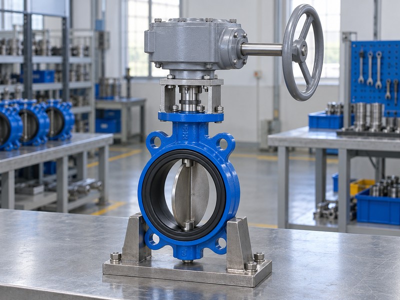
5. What output items join butterfly valve gearbox parts?
The output side of butterfly valve gearbox parts transfers rotation and torque into the valve stem through the selected drive arrangement. A socket, drive bush, coupling or keyed bore needs its own dimensions, tolerances and orientation. The same nominal valve size can use different shaft profiles and effective engagement lengths.
What makes an output replacement fit?
Trace the mating dimensions. Compare shaft projection, socket depth, usable contact length, retention and axial clearance while preserving proper mounting-face seating. ISO 5211 defines a part-turn attachment scope; actual mating details still govern the selected connection. A replacement bush that bottoms early or contacts only part of the intended profile needs correction through the accepted design and parts process.
- Match profile, orientation and dimensional tolerances.
- Verify effective engagement and axial clearance.
- Retain the specified drive connection and retention method.
Key takeaway: Approve the drive fit from a complete dimension chain before ordering a coupling or bush.
| Check | What you should confirm |
|---|---|
| Profile | Mating shaft and drive geometry agree |
| Engagement | Usable contact meets the accepted design |
| Seating | Axial clearance permits correct mounting-face contact |
6. What supports and seals butterfly valve gearbox parts?
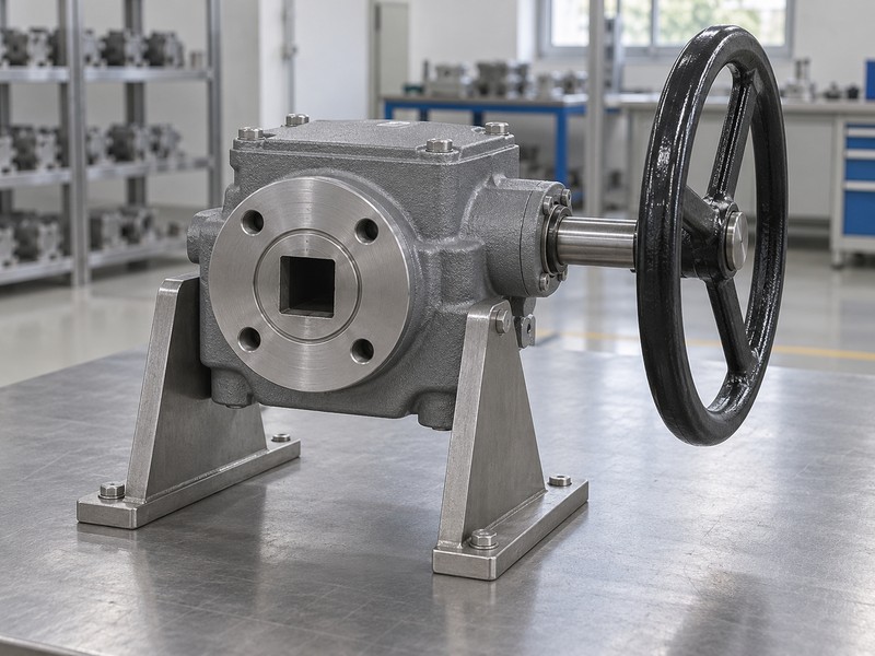
Bearings and seals associated with butterfly valve gearbox parts support shafts and control the relevant lubricant or environmental boundary. Their dimensions, materials, clearances and orientations depend on the actual operator design. A ring or bearing with matching headline dimensions can still have the wrong internal geometry, fit or service limitations.
What should the supplier identify for each item?
Request the full specification. Include the approved bearing or seal designation, material requirement, mating surface condition and any installation orientation specified in the selected manual. Keep lubricant compatibility and operating temperature with the item enquiry. Visible photographs can document condition and location, but they cannot reveal hidden lip geometry, bearing clearance class or every material property needed to approve a replacement.
- Use complete bearing and seal designations.
- Record lubricant and temperature requirements with the item.
- Confirm mating surfaces and specified installation orientation.
Key takeaway: Use the complete supplier item specification for bearings and seals that appear dimensionally similar.
| Check | What you should confirm |
|---|---|
| Bearing | Type and applicable fit or clearance are identified |
| Seal | Geometry and material match the intended boundary |
| Service | Lubricant and temperature conditions are documented |
7. What stops and indicators join butterfly valve gearbox parts?
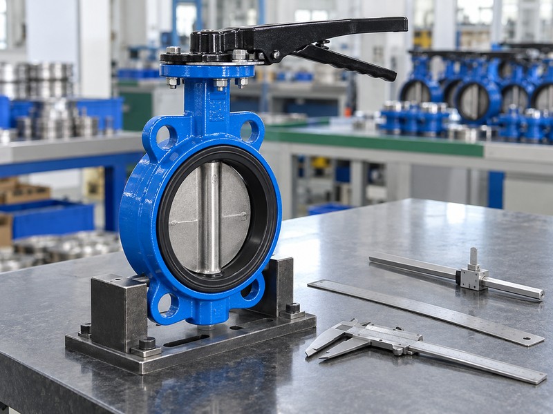
The stops and position indicator within butterfly valve gearbox parts serve different functions and require separate identification. A stop arrangement limits permitted movement according to the selected assembly, while a pointer indicates its indexed position. Neither the pointer appearance nor a replacement stop screw alone establishes accepted disc travel or sealing.
What should follow a changed indication component?
Preserve the accepted reference. Identify the pointer, indicator plate, stop items and locking components from the correct parts list before arranging replacement. Any affected travel setting or indexing needs the selected valve and operator instructions and authorized verification. Record physical endpoint references separately from leakage acceptance, since a pointer at its marked limit does not by itself demonstrate closure performance.
- Identify stops, pointer and locking items separately.
- Retain the selected travel and indexing references.
- Repeat affected authorized checks after a component change.
Key takeaway: Treat indication and travel items as parts of an accepted setting arrangement.
| Check | What you should confirm |
|---|---|
| Stops | Selected arrangement defines permitted travel |
| Pointer | Indexing relates indication to the actual assembly |
| Acceptance | Movement and sealing have separate verification records |
8. What mounting items join butterfly valve gearbox parts?
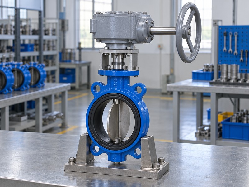
Mounting components around butterfly valve gearbox parts can include the bracket, fasteners, locating features and the valve attachment. Their purpose includes locating the mechanism and carrying the applicable loads. A bolt-pattern match leaves questions about thread depth, engagement, seating and structural capacity that the selected assembly drawing must resolve.
Which fastener details can stores overlook?
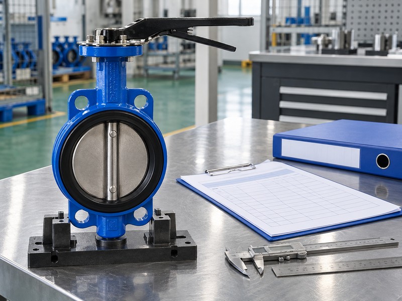
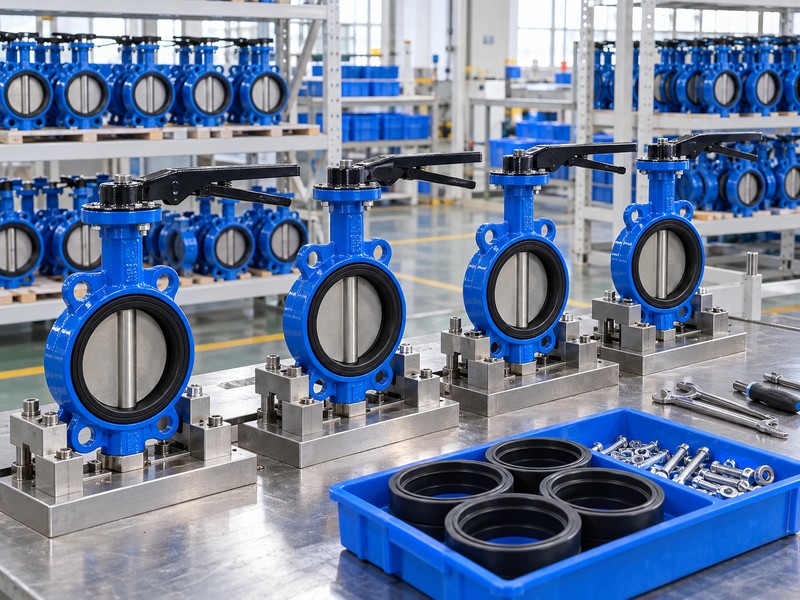
Read the fastener callout. Diameter alone omits thread form, grade, length, coating and any locking requirement specified for the connection. Compare usable engagement and clearance with the actual mating parts rather than copying the length of a previously modified bolt. The generic workstation images illustrate review context; they supply no measured bolt dimensions or substitute bracket load calculations.
- Read thread, grade, length and coating requirements.
- Check usable engagement and seating against mating parts.
- Retain the approved bracket and locating arrangement.
Key takeaway: Order mounting items from full callouts and the accepted attachment design.
| Check | What you should confirm |
|---|---|
| Fasteners | Complete callouts identify the required items |
| Mounting | Actual threads, engagement and seating agree |
| Support | Bracket and attachment loads receive their own review |
9. What records order butterfly valve gearbox parts correctly?
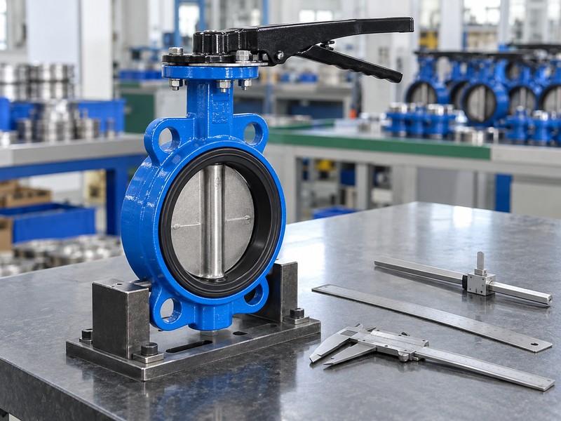
Order butterfly valve gearbox parts with a clear item reference, quantity, assembly identity and required supporting information. State whether the request concerns a single spare, a matched set or a complete replacement operator. Include observed damage and service conditions without presenting an unverified diagnosis as an established cause.
What should the quote resolve before purchase?
Read each offered exception. Ask the supplier to confirm compatibility with the identified assembly and explain any superseded item, changed material or complete-unit recommendation. Retain the reply with the drawing and order records so later maintenance can trace the installed configuration. RUITO can coordinate valve-assembly identification for supplied packages, while actual internal spare availability and repair scope need explicit confirmation.
- Specify item reference, quantity and the assembly revision.
- Distinguish single items, matched sets and complete units.
- Record supersession and material or configuration changes.
Key takeaway: Release a spare-parts order after its identity and offered exceptions are clear.
| Check | What you should confirm |
|---|---|
| Request | Required items have traceable assembly references |
| Offer | Compatibility and exceptions are explicitly addressed |
| Record | Accepted changes remain linked to the installed package |
10. When should butterfly valve gearbox parts mean a new unit?
A request for butterfly valve gearbox parts should become a complete-unit review when damage, unidentified internals or unsupported repair scope prevents a sound spare selection. The decision depends on the selected supplier policy, available evidence and actual condition. A cheaper loose item cannot resolve an unknown housing condition or an untraceable transmission assembly.
What belongs in the repair-or-replace comparison?
Compare the complete job. Include authorized inspection, available spares, repair capability, required verification, installation access and the effect on the controlled assembly configuration. Request current commercial and delivery information for the actual proposed scope instead of assigning a generic service life or replacement interval. Preserve the reason for the decision and the accepted replacement documents so the next enquiry starts from a known baseline.
- Compare authorized repair scope with complete replacement.
- Include required verification and installed interface changes.
- Retain the accepted decision and replacement identity.
Key takeaway: Choose a repair scope that can be identified, executed and verified for the actual assembly.
| Check | What you should confirm |
|---|---|
| Condition | Observed damage and identification gaps are reviewed |
| Scope | Repair policy and available parts support the proposal |
| Release | Replacement configuration and verification are controlled |
Send RUITO the valve and operator identification, available parts list and clear photographs of the required item. We can review the assembly records and confirm what further information is needed for a parts or replacement enquiry. Contact us before ordering from appearance alone.
FAQ
Q1: Can I order a part from a gearbox photograph?
Use the photograph for identification support. Confirm the actual operator, item reference, dimensions and revision before purchase.
Q2: What’s the best reference for an internal gear?
Use the approved parts definition. Ratio and housing appearance cannot establish tooth geometry, material or accepted gear pairing.
Q3: Can I replace the handwheel with a larger one?
Only after review. Check input-torque limits, hub fit, retention, operating access and wheel clearance.
Q4: How do I know whether a drive bush fits?
Review the full mating detail. Compare profile, tolerance, orientation, engagement and axial clearance with the valve shaft.
Q5: Can a pointer prove the valve seals?
No. Position indication, accepted travel and leakage verification answer separate questions.