
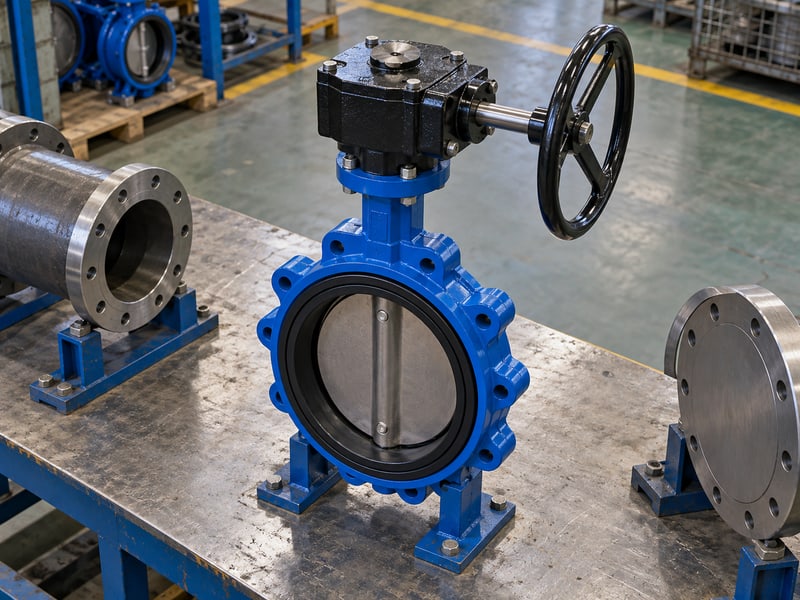
Fix butterfly valve handwheel orientation by providing a stable operating position, clear grip space, readable indication, and a known closing direction. A wheel squeezed behind pipework can make routine isolation difficult. Check the installed operating envelope against the approved gearbox arrangement before choosing its position.
1. What sets butterfly valve handwheel orientation?
The approved manual-drive arrangement and operator access requirements set butterfly valve handwheel orientation. The wheel's location must suit the gearbox input shaft while leaving enough room for the operator's hands and normal standing position.

Which view should the layout show?
Draw the operating position alongside the wheel. A plan view can hide a wheel located above a low beam or beyond an access barrier. Include elevation, nearby equipment, insulation, and the floor or platform from which the valve will normally be operated.
- Mark the wheel centre and diameter.
- Identify the normal access route.
- Show fixed and removable obstructions.
The wheel is often connected to a reduction gearbox, so it makes several revolutions while the disc moves through its approved travel. Wheel spoke angle cannot establish whether the valve is open or closed; the assembly needs its specified indicator or reference method.
What should be approved before purchase?
Key takeaway: Review the operating envelope as part of the complete valve layout. A wheel that fits between pipes may still be unusable from the available platform.
| Layout item | Check |
|---|---|
| Wheel centre | Reach from platform |
| Wheel rim | Hand clearance |
| Indicator | Visible operating reference |
Request the operator dimensions with the valve drawing. Review them before freezing adjacent pipework and access steelwork.
2. How does butterfly valve handwheel orientation affect reach?
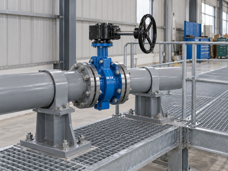
Usable butterfly valve handwheel orientation allows you to reach the rim and apply the required effort without overreaching or losing balance. The review must cover a complete operating cycle, including repeated rotations and the most difficult part of travel.
What should an access check include?
Check the stance under the expected operating effort. Reaching a stationary wheel differs from turning it against valve resistance. Operators need a usable grip, space for arm movement, and a stable surface while wearing the protective equipment required for the location.
- Check access from the intended platform.
- Review grip space with gloves.
- Confirm a stable operating stance.
Apply the project's ergonomic criteria rather than assigning one mounting height to every installation. Operator reach, wheel diameter, gear ratio, access frequency, and surrounding equipment all change the assessment; a wheel above a ladder can be especially difficult when sustained effort is required.
What indicates acceptable reach?
Key takeaway: Reach must be judged during operation, not by fingertip contact. The selected arrangement should support the required effort from a stable location.
| Condition | Observe |
|---|---|
| Normal stance | Balanced footing |
| Repeated turns | Usable grip and arm space |
| High effort | Supported working position |
Review the access layout with the operating team. Resolve awkward reach through an approved operator or platform arrangement before installation.
3. What clearance suits butterfly valve handwheel orientation?
Adequate butterfly valve handwheel orientation clearance includes the rim, hands, and operating movement around nearby equipment. The wheel's diameter alone does not describe the space needed for gripping and turning it.

Which obstructions need checking?
Measure clearance with insulation and guards included. A bare pipe layout can appear workable until insulation, cable trays, or protective covers are fitted. Check the closest obstruction throughout normal grip positions and leave room for the approved removal procedure.
- Check walls, pipes, and access rails.
- Include final insulation thickness.
- Keep neighbouring controls usable.
A compact wafer butterfly valve reduces pipewise installation length, but its manual operator still needs a separate clearance review. In a hypothetical skid, a narrow valve body can fit easily between flanges while its wheel blocks access to an adjacent pump coupling guard.
What clearance should the drawing distinguish?
Key takeaway: Separate wheel clearance from hand and maintenance clearance. A small body footprint cannot establish that the complete manual operator fits.
| Envelope | Purpose |
|---|---|
| Wheel diameter | Physical fit |
| Hand movement | Normal operation |
| Removal route | Operator maintenance |
Mark the limiting obstruction on the layout. Ask for a reviewed alternative if the wheel envelope conflicts with service access.
4. How does butterfly valve handwheel orientation show closing?
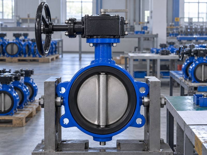
A clear direction marking identifies the closing action for butterfly valve handwheel orientation, while verified indication confirms the final disc position. Many assemblies close clockwise when viewed at the wheel, but the supplied arrangement and markings must govern.
What should the operator verify?
Read the arrow from the actual operating side. A direction description needs a viewing reference, especially where an extension or remote operator changes the access location. Confirm the marked action through the approved functional procedure before placing the assembly in service.
- Identify the marked closing direction.
- Check open and closed indication.
- Record any remote-operator arrangement.
Do not infer the disc position from the orientation of a wheel spoke or from the last direction it was turned. A gearbox can require many wheel revolutions, and an incorrectly indexed pointer can disagree with the valve even when the wheel turns freely.
What makes the marking reliable?
Key takeaway: Direction marking and position indication answer different questions. Verify both against the installed valve and retain a readable reference at the operating point.
| Reference | Meaning |
|---|---|
| Direction arrow | Required wheel rotation |
| Position pointer | Indicated disc position |
| Approved endpoint | Accepted actual travel |
Inspect the labels after installation and painting. Correct missing or ambiguous markings through the supplier's approved identification method.
5. Can butterfly valve handwheel orientation be re-clocked?
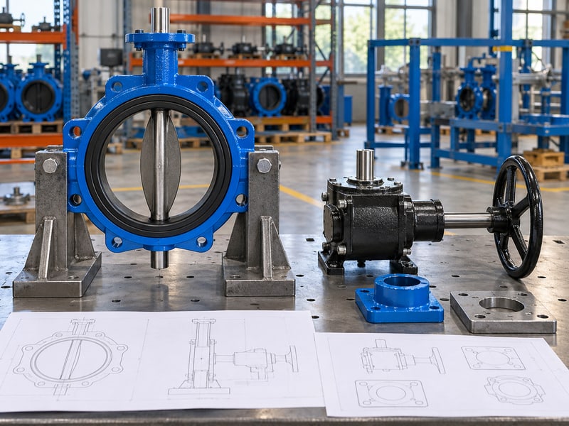
Changing butterfly valve handwheel orientation usually means reviewing the gearbox or remote-input arrangement, and only approved positions are acceptable. Moving the wheel location can alter mounting loads, input alignment, access to stops, and readable indication.
What changes need approval?
Check the complete operator before moving its housing. Some assemblies permit specified gearbox clock positions; others need a different adapter or extension. Removing the wheel from its input shaft does not automatically provide a new housing orientation.
- Confirm permitted gearbox positions.
- Check coupling and input alignment.
- Review stops, markings, and removal access.
For HVAC and district energy installations, account for finished insulation and planned maintenance routes when proposing a change. A position that clears one insulated pipe may create an obstruction for the next valve or prevent an operator from seeing its pointer.
What should a change request show?
Key takeaway: Repositioning needs a reviewed assembly arrangement. Isolate and depressurise the valve before approved dismantling, and control any retained drive load or disc movement.
| Proposed change | Confirm |
|---|---|
| Gearbox clocking | Permitted arrangement |
| New adapter | Engagement and loads |
| Remote input | Alignment and access |
Provide the supplier with the proposed layout and dimensions. Verify travel and indication after any authorised mounting change.
6. What effort fits butterfly valve handwheel orientation?
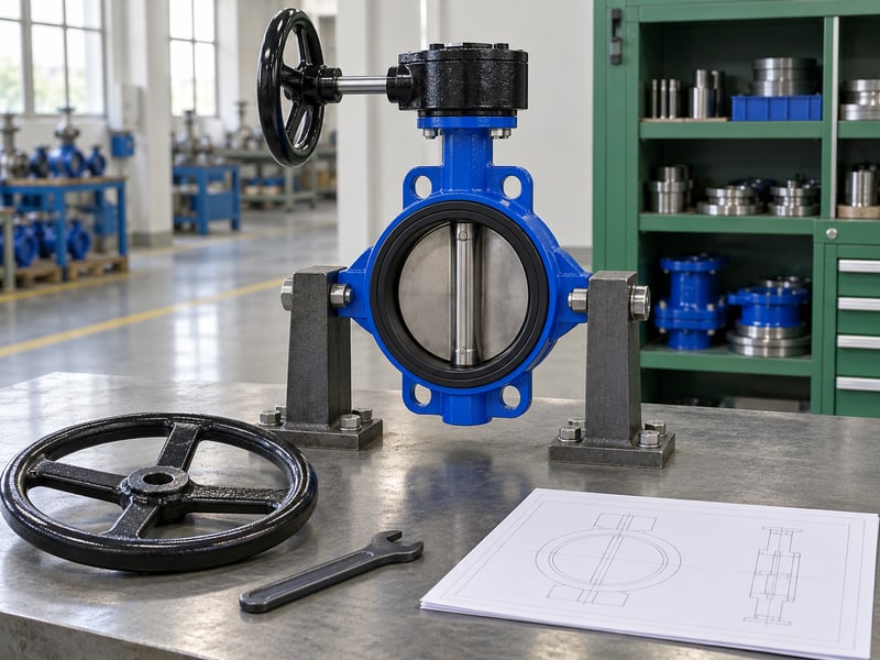
An acceptable butterfly valve handwheel orientation allows the rated operating effort to be applied safely within the wheel, gearbox, and valve limits. A larger wheel can reduce rim force for the same input torque, but it also requires more space and approval.
What governs operating effort?
Review torque before choosing a different wheel. Required effort depends on valve torque, gearbox reduction, mechanical efficiency, and effective wheel radius. Breakaway or final seating can require more effort than the middle of travel, so a freely turning wheel during one part of the stroke is insufficient evidence.
- Obtain the selected valve torque requirements.
- Check gearbox and wheel input limits.
- Confirm the permitted operating method.
Do not fit a pipe over the wheel or use an impact tool to overcome unexpected resistance. Seat damage, disc interference, incorrect stop settings, or stem misalignment needs investigation; extra input force can damage the drive while concealing the original fault.
What should procurement compare?
Key takeaway: Wheel size, reduction ratio, and available operating space need review together. A wheel replacement must retain the rated input connection and load limits.
| Selection item | Effect |
|---|---|
| Wheel radius | Rim force and clearance |
| Gear reduction | Effort and rotations |
| Valve duty | Required output torque |
Ask the supplier to review effort for the actual closing differential. Use an approved drive alternative when manual effort exceeds project criteria.
7. What makes butterfly valve handwheel orientation safe in pits?
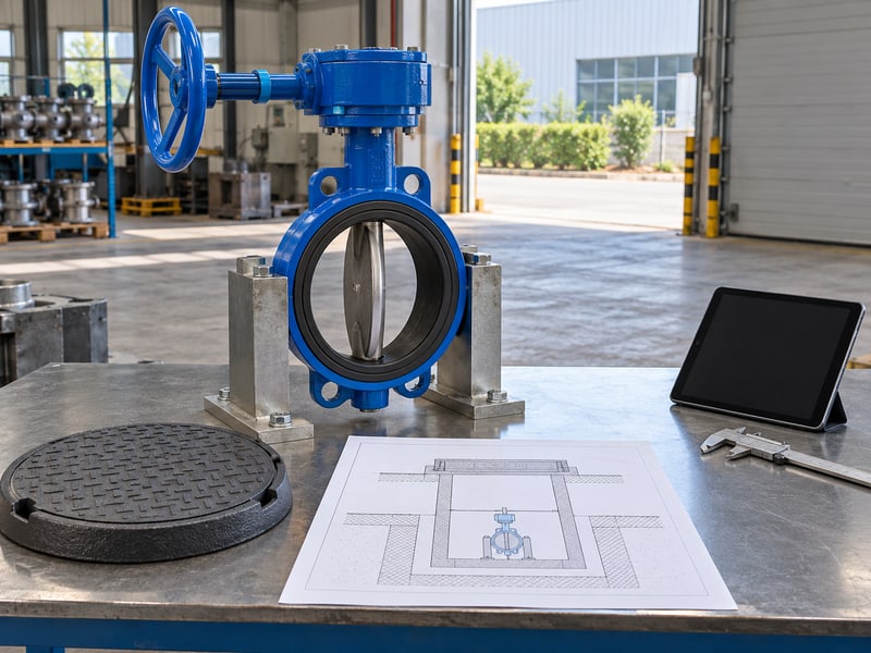
Safe butterfly valve handwheel orientation in a pit provides a defined operating point with usable access, clear indication, and a suitable environmental arrangement. The layout must address how the operator reaches the wheel as well as whether the assembly fits below the cover.
Should operation require pit entry?
Review the access method before selecting the operator. An approved remote input or extension can sometimes move operation to a more accessible point, but it needs its own mechanical review. Where entry is required, the site's access and confined-space procedures govern the work.
- Mark the platform or remote operating point.
- Check cover and ladder clearance.
- Review drainage and flood exposure.
For water and wastewater facilities, a chamber can expose the gearbox to condensation or temporary water accumulation. The operator's specified environmental suitability must match that exposure; ordinary outdoor suitability cannot establish suitability for immersion.
What should the chamber drawing record?
Key takeaway: Pit access and operator protection belong in the valve specification. A wheel reachable only through an unsuitable opening needs a revised access arrangement.
| Chamber feature | Review |
|---|---|
| Operating point | Reach and stable stance |
| Access opening | Cover and movement space |
| Water exposure | Operator protection |
Review the chamber drawing with operations and engineering. Resolve access and environmental limits before ordering the assembly.
8. Can extensions improve butterfly valve handwheel orientation?
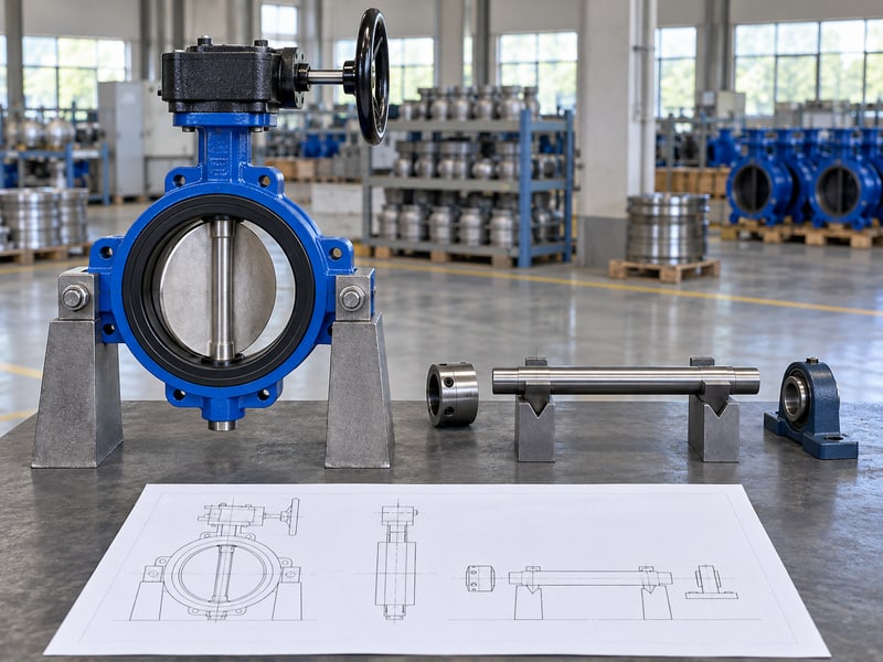
An approved extension can improve butterfly valve handwheel orientation by moving its operating point to a reachable location. It must maintain the required input alignment, transmit the specified torque, and provide the supports and indication needed for the complete drive path.
What must an extension design include?
Specify the complete shaft route and support arrangement. Long shafts can deflect or misalign, and direction-changing mechanisms can affect the operating reference. Confirm couplings, guards, bearings, attachment points, and any allowance for movement rather than ordering an extension by length alone.
- State shaft length and route.
- Confirm torque and support requirements.
- Provide readable indication at the operating point.
A chain operator also needs approval for its input connection, pulling direction, and surrounding access. Chains should remain clear of walkways and adjacent rotating equipment, and the assembly must retain the manufacturer's permitted operating loads.
What should be verified after fitting?
Key takeaway: A remote operator extends the mechanical drive path and its inspection needs. Access improves only when alignment, support, direction, and indication remain correct.
| Extension feature | Check |
|---|---|
| Couplings | Engagement and retention |
| Supports | Alignment and movement |
| Operating point | Direction and indication |
Request an approved assembly drawing for the extension. Verify full travel from the remote operating point before handover.
9. How is butterfly valve handwheel orientation maintained?
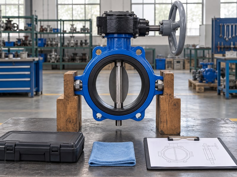
Maintain butterfly valve handwheel orientation by keeping the operating envelope clear and checking the wheel, input connection, markings, and gearbox through the approved inspection schedule. Changes around the valve can make an accepted installation difficult to operate later.
Which changes can restrict operation?
Inspect access after nearby equipment changes. Added insulation, pipe supports, stored materials, or replacement guards can reduce grip space. Check for loose or damaged wheel retention parts and report increased effort rather than normalising it as routine wear.
- Keep the operating route clear.
- Inspect wheel and hub condition.
- Check indication and specified service points.
Before removing a wheel, gearbox, or drive connection, follow the required pressure isolation and restraint procedure. The disc may move under process forces if the drive is disconnected; maintenance must also account for stored loads in any attached powered or spring arrangement.
What should a maintenance record capture?
Key takeaway: Record changes in effort, access, and indication against the accepted arrangement. Those observations help distinguish an access problem from a mechanical fault.
| Observation | Record |
|---|---|
| Rising effort | Travel position and conditions |
| Reduced clearance | New obstruction |
| Pointer discrepancy | Actual verification method |
Report faults with valve identification and operating conditions. Keep the assembly out of the affected duty until the required corrective checks are complete.
10. What butterfly valve handwheel orientation data aid selection?
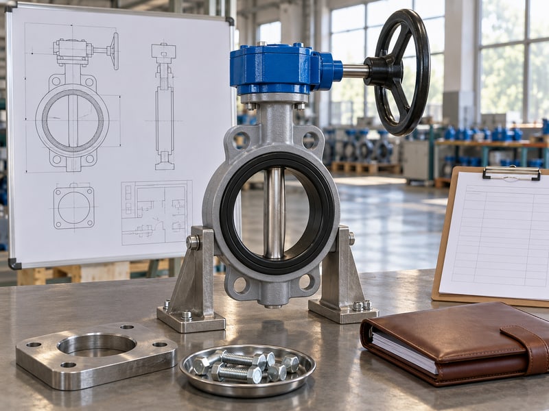
A useful butterfly valve handwheel orientation enquiry combines valve duty with the operator's access, effort, clearance, and maintenance requirements. It lets the supplier review a complete manual-drive arrangement before the surrounding layout is fixed.
Which project details should you send?
Provide the operating location with the process conditions. Include fluid composition, temperature, maximum closing differential, and operating frequency. Mark platform level, wheel clearance, viewing direction, insulation, and any proposed remote-input route on the layout.
- Identify connection style and valve size.
- Define permitted manual effort.
- Include external exposure and access limits.
Request the general arrangement drawing, operator sizing basis, instructions, and replacement-part identification for the selected assembly. These records should relate to its actual drive connection, because a nominal pipe size cannot establish wheel effort or gearbox compatibility.
What should the handover file contain?
Key takeaway: Keep access geometry and operating limits with the maintenance instructions. A later replacement wheel or operator needs review against that same information.
| Document | Purpose |
|---|---|
| Layout | Reach and clearance |
| Operator details | Effort and drive limits |
| Instructions | Direction and maintenance |
Send RUITO your duty and installation layout to review the manual valve arrangement; contact us today with the proposed wheel location. Ask for confirmation of access, operating effort, and approved mounting before purchase.
FAQ
Q1: Can I tell valve position from the handwheel spokes?
No. A reduction gearbox requires multiple wheel turns, so use its verified position indicator or the approved valve reference method.
Q2: What's the best height for a valve handwheel?
Use the project's access and ergonomic criteria. Wheel size, operating effort, platform geometry, protective equipment, and operator reach all affect the suitable location.
Q3: Can I fit a bigger wheel to make operation easier?
Only with approval. Confirm hub fit, input loads, clearance, and the cause of high effort before changing wheel diameter.
Q4: How do I know which direction closes the valve?
Follow the supplied marking and instructions. Verify direction from the actual operating side, especially with extensions or remote-input mechanisms.
Q5: Can I operate a pit valve from above the cover?
Only through an approved accessible arrangement. Review the extension or remote input, support, environmental protection, direction marking, and position indication together.