
Check butterfly valve handwheel dimensions against the complete operator drawing and the available installation space. A replacement can match the rim diameter yet fail at the hub, shaft or mounting interface. Start with the valve and gearbox identification, then record each dimension from a defined reference point.
1. Which butterfly valve handwheel dimensions matter?
The useful butterfly valve handwheel dimensions include rim diameter, hub geometry, shaft projection, operator height and the assembled wheel envelope. You need these values together. A catalogue entry showing only the valve's nominal pipe size cannot establish whether an existing wheel or replacement operator will fit.
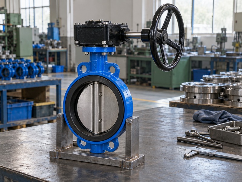
How should you organize the dimensional request?
Separate the wheel part drawing from the complete valve assembly drawing. The part drawing defines the wheel's bore, keyway or other drive feature and retaining method. The assembly drawing locates the wheel relative to the gearbox, valve stem and pipe centerline. Record units, tolerances and the revision on both.
Include photographs for identification, but use approved dimensions for acceptance. Camera perspective can make a rim look smaller or hide a shaft shoulder behind the hub. If a dimension is missing, ask the supplier to add it rather than estimating it from an image. This gives purchasing and site engineers a common basis for checking the quotation and received assembly.
- Identify the wheel and assembled operator.
- Record units and drawing revision.
- Request missing dimensions before ordering.
| Drawing | Information |
|---|---|
| Wheel part | Hub, drive feature and rim |
| Gearbox | Input shaft and mounting |
| Complete assembly | Position and installed envelope |
2. How do you measure wheel diameter and rim size?
Measure butterfly valve handwheel dimensions across the actual outer rim, through its center, and record the rim's grip section separately. The outside diameter defines the rotating envelope. The grip section affects hand access and handling, while the hub and spokes can project beyond a flat diameter measurement.
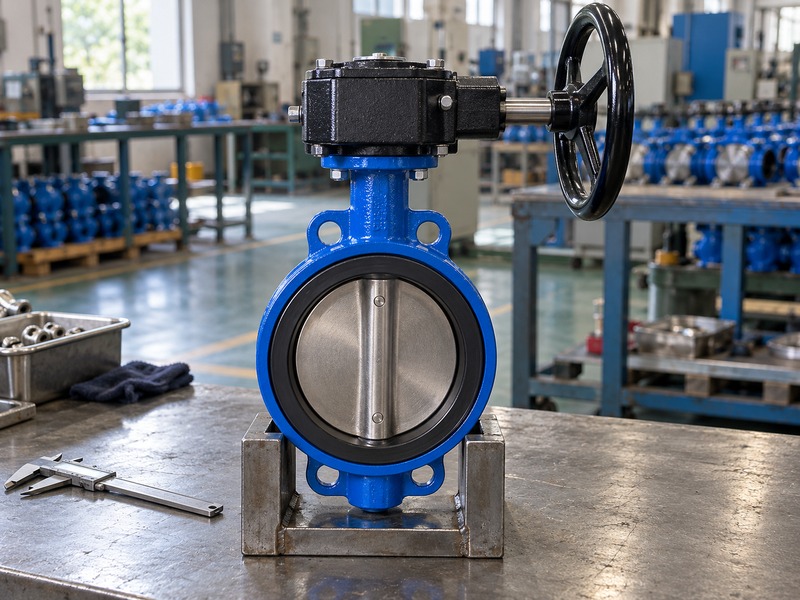
What can distort a quick site measurement?
Check whether the rim is bent or coated with material that obscures its original shape. A damaged wheel can give different measurements in different directions. Measure an accessible isolated component with suitable tools and follow the site's access procedure; do not reach across a moving mechanism. Include a side view to record wheel dish or offset.
Two wheels with the same outside diameter can place the rim at different distances from the gearbox. Also distinguish nominal catalogue dimensions from measured acceptance values. The supplier should state the permitted tolerance and the reference surfaces. A single tape measurement may identify a likely replacement, but it does not verify the fit or the load-carrying details of the hub.
- Measure the outer rim through its center.
- Check for bending or damage.
- Record rim section and wheel offset.
| Measurement | Purpose |
|---|---|
| Outside diameter | Rotating envelope |
| Rim section | Grip space |
| Wheel offset | Projection from the hub |
3. How do hub bore and retention affect fit?
Hub fit is one of the butterfly valve handwheel dimensions that must match the input shaft precisely. Bore diameter alone is insufficient. The drive may use a key, flats, splines or another approved feature, while a nut, pin or retaining screw prevents the wheel moving off the shaft.
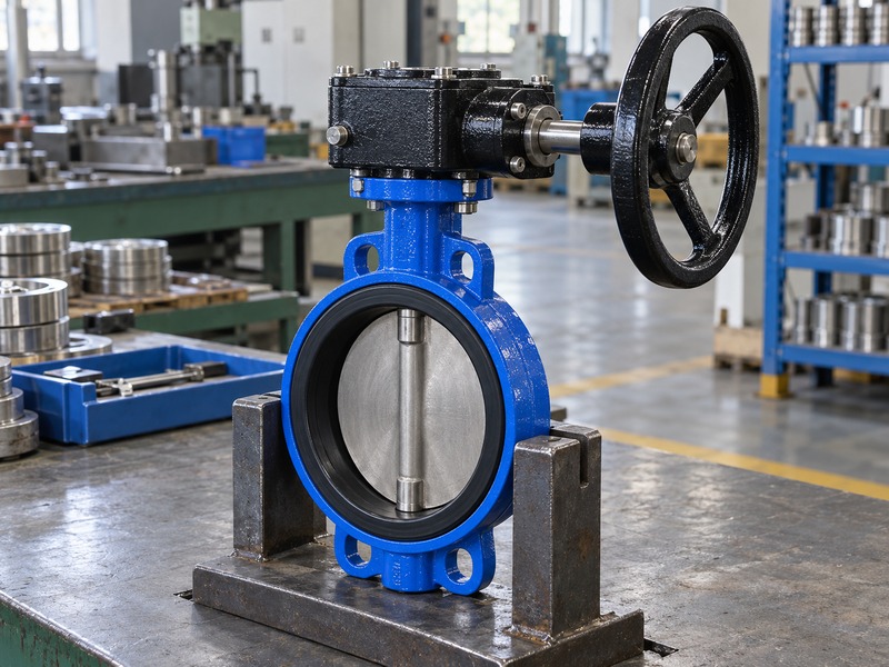
What belongs on a spare-wheel specification?
Record the shaft shape, engagement length, shoulder location and retaining arrangement from the approved operator details. Include keyway dimensions or the exact drive designation where applicable. Do not enlarge a hub, drill a new retaining hole or substitute a loose key without engineering approval. Those changes affect the part that carries manual input torque.
A replacement that slides onto the shaft can still have excessive backlash or inadequate engagement. For a butterfly valve handwheel dimensions enquiry, provide the gearbox manufacturer and identification alongside the valve details. If the original wheel is missing, the input-shaft drawing or a controlled inspection can establish the interface more reliably than selecting a visually similar spare.
- Match the complete drive geometry.
- Confirm engagement and retention.
- Avoid unapproved hub machining.
| Interface detail | Mismatch consequence |
|---|---|
| Drive shape | Slip or poor torque transfer |
| Engagement length | Overloaded contact area |
| Retaining feature | Axial movement or loss of wheel |
4. How do you check handwheel clearance?
Use butterfly valve handwheel dimensions to create a three-dimensional clearance envelope around the assembled operator. Include the wheel rim, the user's hand and nearby fixed objects. A rim that rotates without touching a wall can still leave too little room for a safe grip or maintenance access.
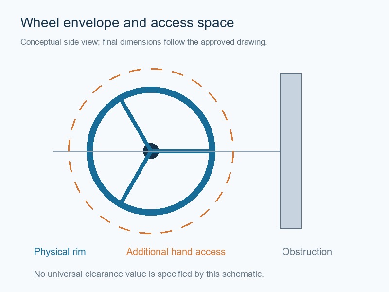
Which reference points make a clearance sketch useful?
Start at the pipe centerline and valve stem centerline, then locate the gearbox input shaft. Add the actual wheel radius and its side projection. Show the nearest wall, pipe, support, insulation and cable tray in the relevant views. Record hand access as a separate project requirement rather than assuming it equals the wheel diameter.
The conceptual drawing should distinguish physical parts from the space a person needs to operate them. Do not use a generic sketch as a fabrication drawing or an approved clearance standard. The equipment layout and site's access requirements determine the final allowance. When the package designer changes insulation thickness or support locations, repeat the envelope check before freezing the arrangement.
- Use named centerlines and surfaces.
- Add grip and maintenance space.
- Recheck surrounding layout changes.
| Envelope | Reference |
|---|---|
| Physical wheel | Input-shaft centerline |
| Hand access | Actual operating position |
| Nearby structure | Approved equipment layout |
5. How do diameter and gearbox ratio affect effort?
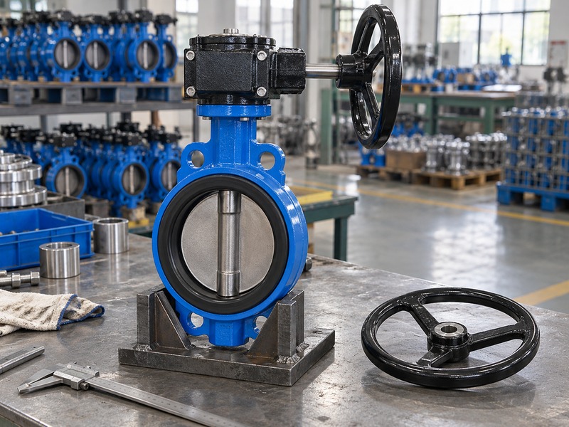
Butterfly valve handwheel dimensions influence manual effort through the effective wheel radius, while the gearbox ratio determines mechanical reduction. Both must suit the required valve torque. A larger rim can reduce hand force for a given input torque, but it also changes space, reach and the load a user can apply.
Why is a diameter-only substitution incomplete?
The relationship at the wheel is input torque equals tangential force multiplied by effective radius. That relationship does not include gearbox efficiency or the valve's operating torque curve. A supplier can propose a different ratio or diameter to meet an agreed effort requirement, but the complete assembly needs review. Check the number of turns, practical closing time, input limit and allowable valve-stem torque.
The replacement wheel must also withstand the expected handling load. Increasing diameter can make it easier to exceed the original design input, so verify that any limiting arrangement remains appropriate. If an existing valve becomes hard to move, investigate the duty and mechanical condition before treating wheel size as the cure.
- Specify acceptable operating effort.
- Check turns and closing time.
- Keep input and stem loads within approval.
| Design variable | Related check |
|---|---|
| Wheel radius | Effort and envelope |
| Gear ratio | Turns and output capacity |
| Input limit | Protection of downstream parts |
6. How do you locate the wheel on the complete valve?
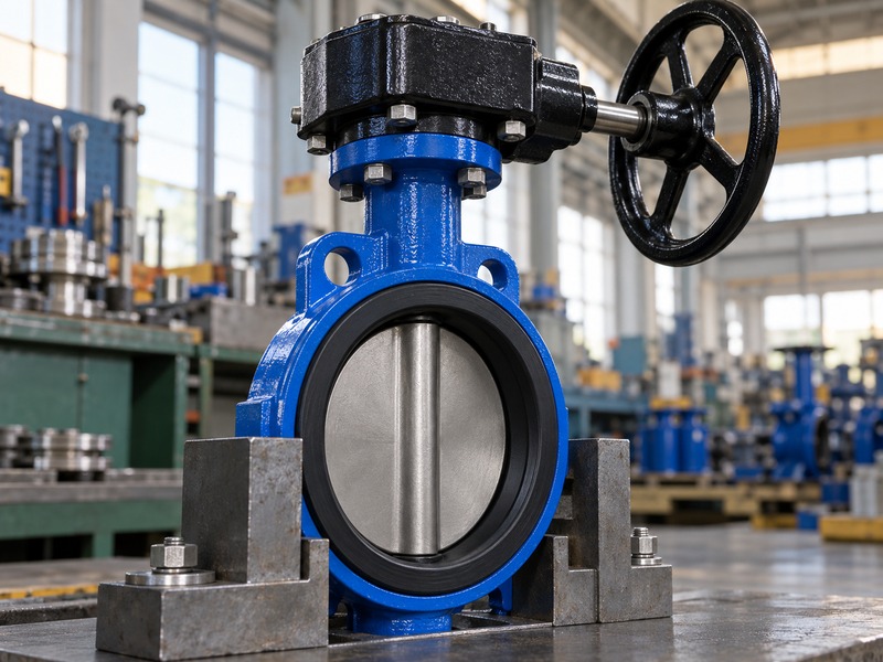
Record butterfly valve handwheel dimensions from a fixed assembly datum, normally the pipe or valve stem centerline shown on the approved drawing. Overall height alone cannot locate a side-mounted rim. You need its horizontal projection and the operator's orientation in plan and elevation.
What changes when the mounting position changes?
A gearbox can have an approved alternative mounting orientation, but that option should appear on the actual assembly drawing. Rotating it can move the wheel toward a wall, alter the accessible operating side or change how the indicator is read. The mounting flange, coupling and stops still need to remain correctly aligned with the disc.
For a butterfly valve handwheel dimensions review, compare the proposed operator orientation with the valve's connection drawing and equipment layout. Do not treat a catalogue outline for another gearbox size as an exact envelope. Ask for the selected operator dimensions after torque sizing, since changing the gearbox can alter the height and projection even when the valve body remains unchanged.
- Dimension the selected operator orientation.
- Use plan and elevation views.
- Recheck after gearbox sizing changes.
| Location dimension | What it prevents |
|---|---|
| Height above pipe center | Overhead interference |
| Side projection | Wall or adjacent-pipe conflict |
| Operating side | Inaccessible wheel position |
7. Which mounting dimensions belong in a conversion review?
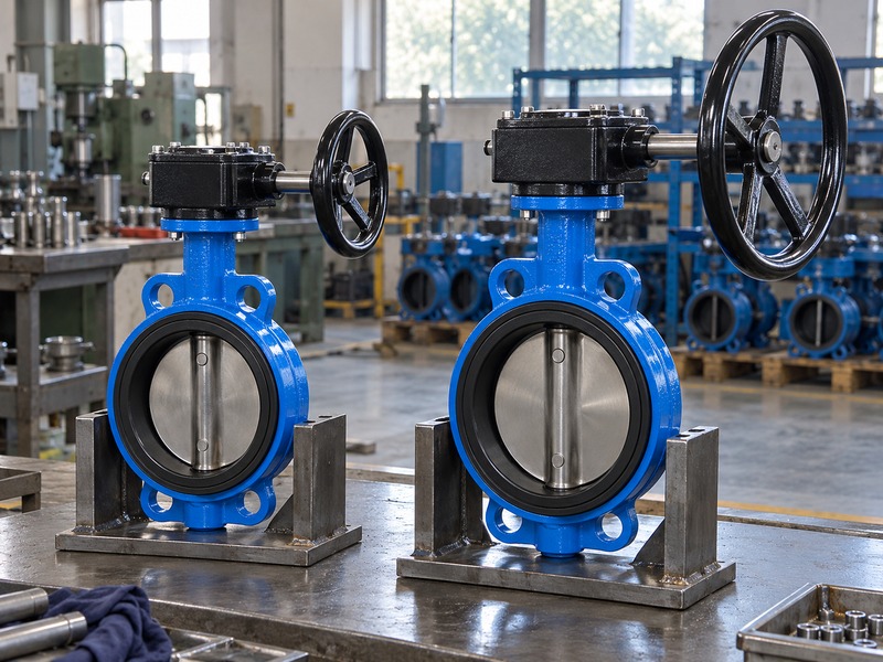
Butterfly valve handwheel dimensions must be checked with the mounting interface when converting a lever valve to a geared operator. Record the mounting pattern, stem drive and coupling height. A common flange designation can describe part of the interface without confirming every mechanical and load requirement.
How should you handle adapters and brackets?
Include any bracket or adapter in the approved load path. Its thickness changes the coupling engagement and the operator height. Bolt access and fastener length may also change. Check that the mounting arrangement carries the operating torque without imposing unintended side loads on the stem.
A coupling that bottoms out can prevent the mounting faces seating correctly, while inadequate engagement can allow damage under load. The valve's pressure boundary should not be altered to accommodate an operator. Request the supplier's complete conversion drawing, required parts and inspection method. After an approved conversion, verify actual disc travel and the indicated end positions in a safe isolated condition before returning the assembly to service.
- Include every adapter in the drawing.
- Check coupling engagement and bolt access.
- Verify actual travel after conversion.
| Detail | Review item |
|---|---|
| Mounting pattern | Accurate hole and fastener geometry |
| Coupling height | Engagement without bottoming |
| Bracket | Torque load path and stiffness |
8. How do you verify dimensions on receipt?
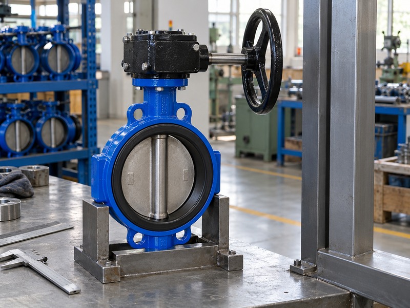
Verify butterfly valve handwheel dimensions against the approved revision and agreed inspection points. Check the complete assembly as well as the spare part. The received wheel may be dimensionally correct by itself while a different gearbox or coupling moves it outside the approved installation envelope.
Which findings should stop release?
Record deviations with the measured value, specified value, units and a clear photograph of the reference surfaces. A bent rim, loose hub or damaged retention needs review even when the outside diameter falls within tolerance. Check whether protective packing concealed transport damage or loaded the input shaft. For an OEM repeat order, compare the received assembly with the frozen drawing and approved sample record.
A butterfly valve handwheel dimensions inspection request should identify which values are critical for installation and which require supplier confirmation. Do not accept a changed wheel size as a harmless cosmetic difference. Ask engineering to confirm the effect on effort, fit, access and packing before approving the deviation.
- Inspect against the approved revision.
- Record measured deviations clearly.
- Review wheel changes through controlled approval.
| Finding | Action |
|---|---|
| Wrong hub or retention | Hold for interface review |
| Bent rim | Check transport damage and replacement |
| Changed envelope | Review installation and effort |
9. What should you send with a dimensional enquiry?
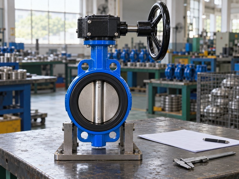
A useful butterfly valve handwheel dimensions enquiry includes identification, drawings, service duty and the available space. State whether you need a spare wheel, a complete gearbox or a valve assembly. Each request has a different interface boundary and a different set of dimensions to approve.
How can you reduce quotation revisions?
Send the existing identification photographs and the latest available assembly drawing together. Mark the required operating side and any nearby obstruction in a simple site sketch. State the maximum closing differential pressure so the operator can be selected before its envelope is finalized. Include the permitted effort, access restrictions and maintenance requirements where the project defines them.
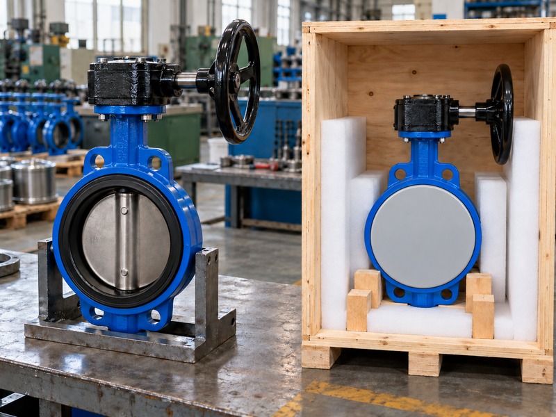
Ask the supplier to list assumptions and missing information rather than filling gaps with a nominal pipe size. Once the dimensional and torque review is complete, freeze the selected arrangement and retain it with the purchase order. Packing dimensions can then be based on the actual assembly, with protection around the rim and shaft rather than a generic valve-body box.
- Define the replacement boundary.
- Provide service and space inputs together.
- Freeze the selected assembly before packing approval.
| Input | Supplier decision |
|---|---|
| Part identification | Correct wheel or operator interface |
| Operating duty | Torque and ratio selection |
| Site sketch | Assembly envelope and access |
10. What do buyers ask about handwheel dimensions?
Q1. Can I select a wheel from the valve DN alone?
No. DN identifies nominal valve size. Wheel fit depends on the selected operator, shaft interface, torque requirement and available space.
Q2. Can two wheels share a diameter and still be incompatible?
Yes. Their hub bore, drive feature, engagement, retention or offset can differ. Check the approved part and assembly drawings.
Q3. What is the best clearance around the rim?
Use the project's access requirements and actual operating position. Add grip and maintenance space to the physical wheel envelope rather than applying an unsupported universal gap.
Q4. Can I trim a wheel to clear nearby pipework?
Do not modify the wheel without engineering approval. Review the layout, approved mounting options or a different operator arrangement instead.
Q5. How do I know a crate fits the approved assembly?
Compare its internal space with the complete protected envelope. Allow for body restraints, face covers and wheel protection without loading the input shaft.
Send your operator identification, dimensioned sketch and service duty when you contact us. RUITO can review the assembled fit and identify the drawing details needed before a replacement or repeat order.