
Avoid handwheel butterfly valve mistakes by checking the complete gearbox, stem connection and service duty before selecting the wheel. A geared manual operator turns the disc through a quarter turn. If a replacement wheel fits but the valve remains hard to close, wheel diameter alone cannot confirm torque capacity or acceptable operating effort.
1. What makes a handwheel butterfly valve different?
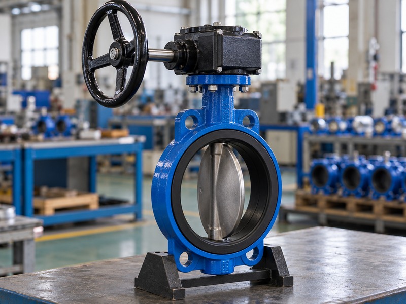
A handwheel butterfly valve has a rotary valve body and a separate manual reduction mechanism. You turn the wheel several times while the gearbox rotates the valve stem through its specified travel. The wheel does not lift a threaded gate or move the disc along the pipe.
Which parts must work together?
Follow the load path from wheel rim to input shaft, gearset, output coupling and valve stem. Each joint needs an approved fit and a load rating that covers the selected duty. A loose wheel hub can create lost motion even when the gearbox remains sound. A slipping coupling may let the position indicator move while the disc stays behind.
During an isolated bench check, compare actual disc travel with the operator stops and indicator. Keep that relationship in the inspection record so a replacement gearbox does not introduce a different output orientation. Ask the supplier to identify the operator and coupling on the valve assembly drawing rather than quoting a wheel as an interchangeable accessory.
- Identify the valve and operator separately.
- Confirm coupling geometry and retention.
- Compare indicator movement with actual disc travel.
| Part | What it controls |
|---|---|
| Handwheel | Manual input and reach |
| Gearbox | Reduction and output travel |
| Valve assembly | Pressure boundary and sealing |
2. When should you choose a wheel instead of a lever?
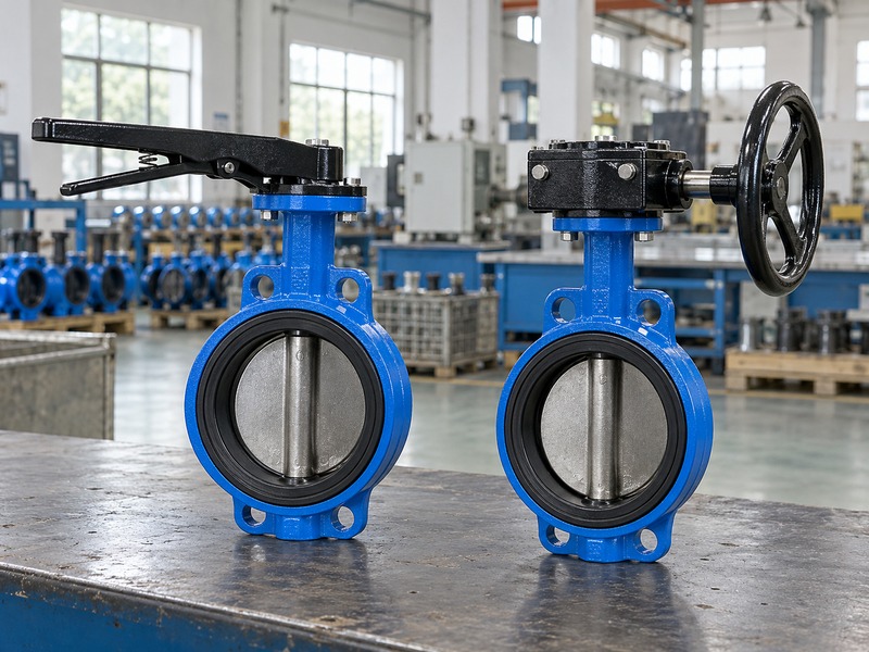
Choose a handwheel butterfly valve when the approved lever arrangement would demand excessive force, lack useful positioning or occupy an unsuitable sweep. A lever can suit accessible valves with manageable torque. The correct choice depends on the actual pressure difference and operating task, rather than a universal pipe-size cutoff.
How does the operating task change the choice?
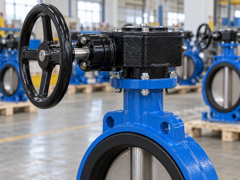
A lever gives direct quarter-turn movement and can make frequent local operation convenient. A gearbox reduces input effort but adds wheel turns and closing time. That trade can suit occasional isolation on a water circuit where an operator can reach the valve safely. It can become inconvenient on a frequently cycled process line.
Consider how often operators work the valve, whether they wear gloves and whether they must hold a particular position. If the process requires remote operation or a defined response to loss of power, specify an appropriate powered assembly and control strategy. Adding a larger wheel cannot provide those functions or convert a local manual valve into an automatic shutdown device.
- Record operating frequency.
- Check accessible standing position.
- Define any remote-operation requirement.
| Operator | Selection question |
|---|---|
| Lever | Can the user complete the sweep safely? |
| Handwheel | Are effort and turns acceptable? |
| Powered drive | What response must the system perform? |
3. How do you check the gearbox output rating?
Size a handwheel butterfly valve operator against the valve's required breakaway, running and closing torque at the stated duty. Use the selected manufacturer's torque data and service allowance. A gearbox label showing a large output capacity does not establish the safe load of the valve stem.
Which conditions belong on the torque request?
Give the supplier the medium, temperature, maximum closing differential pressure, seat material and operating frequency. Include long idle periods or deposits that may affect initial movement. Request the input effort associated with the proposed wheel and ratio, plus the permitted operator input. Compare that assembly with the valve's allowable stem torque and the project allowance.
Avoid selecting the largest available gearbox without checking the downstream parts. A high reduction ratio can make excessive stem loading easy to apply without much hand effort. For a handwheel butterfly valve replacement, keep the coupling, mounting bolts and mechanical stops within the same approved assembly review. Record any change in operator size before releasing a repeat order.
- Specify maximum closing differential pressure.
- Check required output and allowable stem torque.
- Retain the approved ratio and coupling details.
| Value | Use |
|---|---|
| Required valve torque | Establish operating demand |
| Operator output rating | Check available capacity |
| Allowable stem torque | Limit transmitted load |
4. How does wheel diameter affect hand effort?
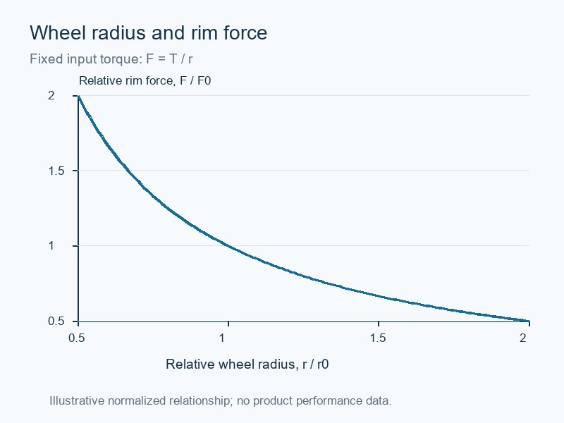
A larger handwheel butterfly valve wheel provides a longer input radius, which can reduce the tangential force needed for the same input torque. It also occupies more space. The simple relationship between rim force and radius applies at the wheel; gearbox losses and valve torque still require separate assessment.
What does the force calculation leave out?
For a force applied tangentially at the rim, input torque equals force multiplied by effective radius. A calculated comparison can explain why changing wheel diameter affects effort, but it is not a product torque rating. Actual users may push at a different angle or grip closer to the hub. Gear efficiency, bearings and seal friction also affect the complete assembly.
Use the supplier's stated handwheel input requirement for final approval. Check both initial breakaway and final closing, because comfortable running movement can hide a difficult end of travel. Do not add a pipe, extension bar or other improvised handle to increase force. If the specified assembly is difficult to operate, investigate the cause before changing the available input.
- Use effective rim radius.
- Separate input torque from valve output torque.
- Investigate rising effort instead of adding a bar.
| Change | What to recheck |
|---|---|
| Larger wheel | Clearance, reach and input limit |
| Different ratio | Turns, effort and closing time |
| Higher effort | Pressure difference and mechanical condition |
5. Which valve materials suit the service?
Select the pressure boundary and wetted materials of a handwheel butterfly valve for the fluid and simultaneous temperature-pressure conditions. The manual operator does not establish chemical compatibility or gas-service suitability. External corrosion around the wheel and gearbox also needs its own environmental review.
How should you separate water, oil and chemical duties?
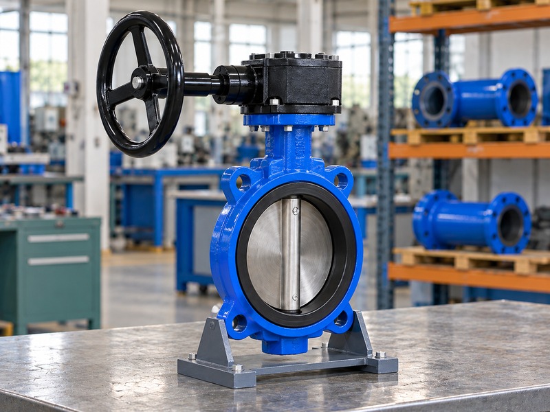
For documented RUITO water-service configurations, engineering selects the body, disc, stem, elastomer and coating as a complete arrangement. An EPDM water seat should not be substituted for an approved oil-service material because both valves have the same wheel. Chemical duties may require a continuous lining, suitable backing and a compatible shaft seal. Drinking-water applications need approval covering the actual contact materials and model.
Keep pressure-temperature data tied to that same configuration. PN identifies a rating system, while the model's permitted operating conditions depend on its materials and construction. A common casting size or matching flange drilling does not make two services interchangeable. Include the fluid composition and cleaning chemicals on the purchase enquiry before choosing the operator package.
- List the complete fluid composition.
- Check every wetted material.
- Review external environment separately.
| Service input | Evidence to request |
|---|---|
| Water or drinking water | Model-specific materials and applicable approvals |
| Oil | Approved elastomer and temperature range |
| Chemical liquid | Complete lining and seal compatibility |
6. What installation clearance does the operator need?
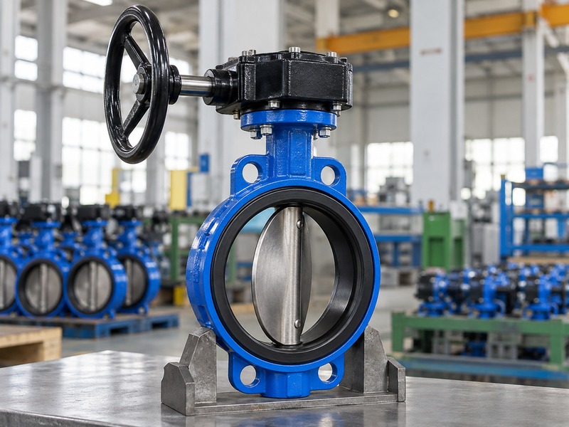
A handwheel butterfly valve needs clearance for the wheel rim, gearbox, user grip and future maintenance. Checking only face-to-face length leaves those spaces unresolved. You also need the valve disc's opening envelope to clear the actual pipe bore and adjoining components.
Which drawing views prevent site interference?
Use plan and elevation views referenced to the pipe and stem centerlines. Show the wheel's outer envelope and the space occupied by the user's hand, along with nearby insulation, supports, walls and cable trays. Include the gearbox cover and coupling removal paths when maintenance requires them. For a handwheel butterfly valve in an equipment package, compare the complete assembly with the skid model before freezing the pipe layout.
Do not rotate or relocate a gearbox on site without checking the mounting arrangement, indicator and stops. A mounting position that clears a wall can still place the wheel beyond comfortable reach. Ask for a revised assembly drawing when any operator orientation changes during approval.
- Show wheel and hand clearance.
- Check disc clearance against the actual pipe bore.
- Reserve access for operator maintenance.
| Envelope | Reason to check |
|---|---|
| Wheel sweep | Avoid contact with surrounding structures |
| Disc travel | Avoid pipe and equipment interference |
| Removal space | Allow planned maintenance |
7. Can the gearbox hold an intermediate position?
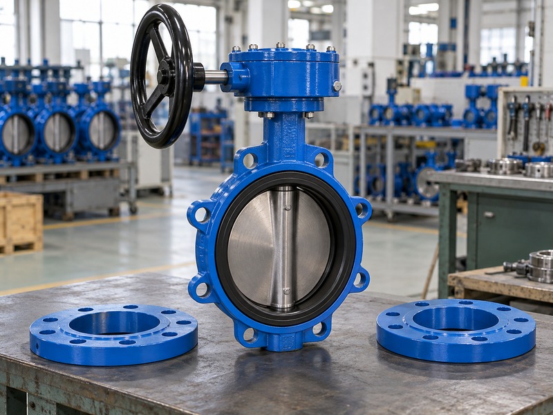
A handwheel butterfly valve can hold a selected position only when the approved operator and valve arrangement support that duty. Some worm operators have a documented self-locking design. Do not assume every gearbox resists back-driving or that a position lock establishes safe process isolation.
What must you confirm before using it for throttling?
Ask for the permitted control range, differential pressure, flow conditions and holding arrangement. A disc can experience changing hydraulic torque as it moves through the flow. Vibration, cavitation or poor low-opening behavior may limit a particular application even when the handwheel stays still. An indicator shows mechanical position and does not measure flow or prove seat tightness.
If a lock is required, identify whether it secures the wheel, input shaft or output mechanism. Keep its intended function distinct from the site's isolation procedure. For a water balancing task that requires repeatable measurement, consider the appropriate balancing product and its approved curve rather than assuming a manual isolation butterfly valve provides the same function.
- Confirm the operator's holding design.
- Obtain application limits for throttling.
- Separate position indication from sealing proof.
| Feature | What it establishes |
|---|---|
| Position indicator | Mechanical travel reference |
| Approved lock | Specified position restraint |
| Isolation procedure | Controlled maintenance boundary |
8. What should you do when wheel effort increases?
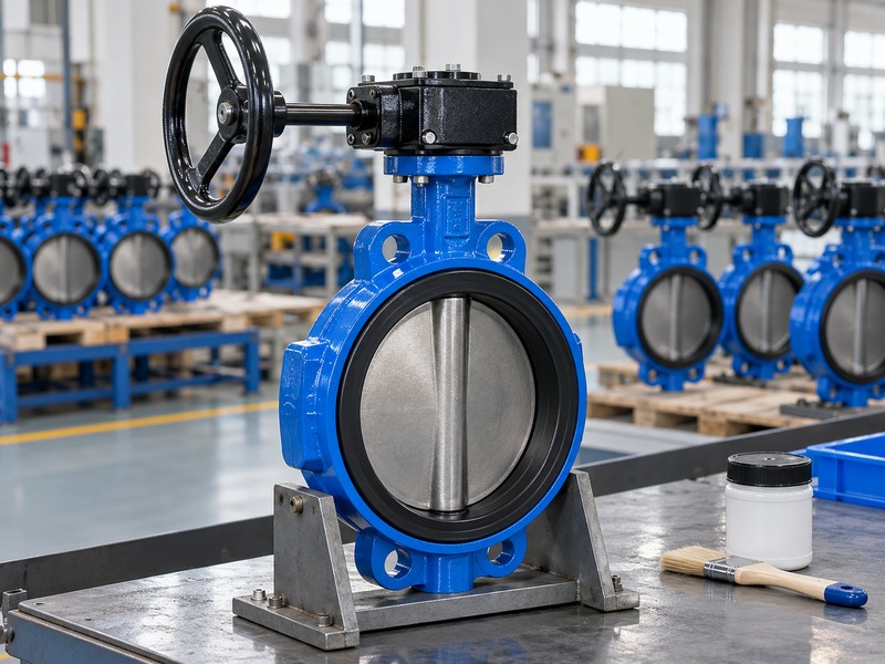
Stop forcing a handwheel butterfly valve when the operating effort rises unexpectedly. Compare current differential pressure and service conditions with the approved duty. If a mechanical inspection is needed, isolate the system, release trapped pressure and follow the model-specific maintenance instructions before disturbing the assembly.
How can you narrow the cause without damaging parts?
Record whether the difficulty occurs at breakaway, throughout travel or only near closing. Note changes in temperature, deposits, pipework or operating frequency. During an authorized isolated inspection, check the wheel hub, coupling and external mounting for damage or looseness. Seat obstruction, disc interference and a damaged gearbox need different corrective work.
Avoid changing end stops to compensate for leakage before confirming their correct positions. A longer travel setting may overload the seat without fixing the original fault. Keep the operator attached to a pressurized valve unless the manufacturer supplies an approved procedure for the specific task. Send the supplier the valve identification, pressure conditions, photographs and the point of travel where the problem appears.
- Record where resistance starts.
- Check recent process or pipework changes.
- Use approved spares and maintenance procedures.
| Observation | Investigation direction |
|---|---|
| Hard at breakaway | Seat condition and differential pressure |
| Hard through travel | Alignment, bearings and gearbox |
| Hard near closing | Obstruction, stops and seat fit |
9. What should the purchase and inspection records include?
A handwheel butterfly valve order should identify the valve duty and the complete manual operator assembly. Include the wheel, gearbox, mounting, coupling, travel direction and inspection requirements. This prevents a repeat shipment from arriving with a different input arrangement or an operator that meets only the bore size.
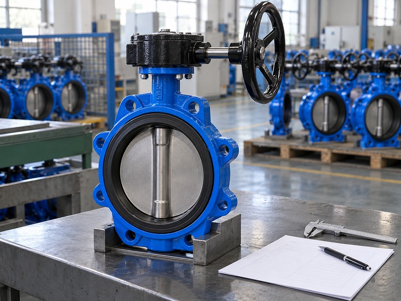
How do you make the approved sample repeatable?
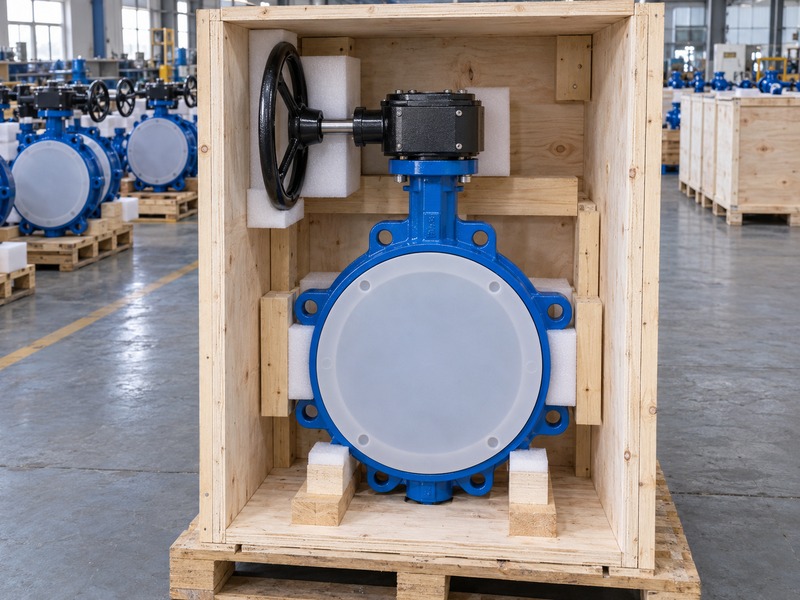
Freeze the assembly drawing and parts list after sample approval. Record the expected full-stroke movement and the operator settings checked during inspection. Keep pressure-test results separate from mechanical operating checks, since one does not replace the other. The shipment should protect the valve faces and prevent transport loads from passing through the wheel or input shaft.
Where several similar valves share an order, link the operator configuration to each item or valve tag. A handwheel butterfly valve with a different connection arrangement requires its own interface check. Send RUITO the fluid, differential pressure, connection standard and installation space so the engineering team can review an appropriate configuration before quotation.
- Freeze the approved assembly revision.
- Match inspection records to each valve.
- Protect the wheel and valve faces during transport.
| Document | Required connection |
|---|---|
| Assembly drawing | Valve, operator and installation envelope |
| Inspection record | Actual item and approved acceptance criteria |
| Packing record | Protected faces and supported body |
10. What do buyers ask about handwheel butterfly valves?
Q1. Can I replace a lever with a handwheel?
Sometimes. The gearbox, mounting and coupling must match the valve's required torque, allowable stem load and travel. Obtain approval for the complete conversion before ordering parts.
Q2. Does a bigger wheel increase the valve pressure rating?
No. Wheel diameter affects manual input and space. The valve's pressure-temperature rating comes from its approved pressure boundary, materials and construction.
Q3. How do I know whether the disc is fully closed?
Check the model's approved indicator and stop settings against actual disc travel during a safe, isolated inspection. Mechanical position alone does not prove the required seat leakage performance.
Q4. Can I use a handwheel valve for emergency automatic closure?
A local manual assembly needs an operator to move it. Automatic closure requires an appropriate powered arrangement and a defined control or failure-response strategy.
Q5. What is the best way to protect it during shipping?
Support the valve body, protect both faces and cushion the operator against impact. Keep crate loads off the handwheel and input shaft.
For a configuration review, send the operating duty and assembly space when you contact us. RUITO can check the connection, materials, operator and inspection scope against the requested service.