
Avoid butterfly valve handwheel extension mistakes by specifying length, torque transmission and structural support on one reviewed assembly drawing. The extension moves the operating point to a more accessible position. A longer rod alone cannot establish a working arrangement for buried, insulated or obstructed equipment.
1. What does a butterfly valve handwheel extension extend?
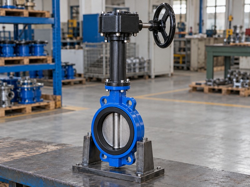
A butterfly valve handwheel extension can extend the valve-stem connection, the gearbox input or another approved operating arrangement. These designs place loads on different components. Identify where the extension sits in the assembly before specifying its length, coupling, supports or operating direction.
Why does the extension location change the design?
An extension between the valve and gearbox carries the torque required at the valve stem. An extension on the handwheel input works on the gearbox's input side and may carry a different torque and speed. Its support and coupling requirements also differ. Some assemblies keep the gearbox near the valve and move only the operating point.
Others place the complete operator above a supported stem extension. Use an assembly drawing to show the selected arrangement and every connection. Do not copy a coupling detail from one side of a gearbox to the other without checking its rating. The drawing should also identify which structure carries the operator's weight, so the valve stem is not used as an unintended support column.
- Locate the extension in the torque path.
- Identify the operator support structure.
- Use the selected assembly drawing.
| Arrangement | Design question |
|---|---|
| Valve-stem extension | What output torque and weight must it carry? |
| Input-shaft extension | What input torque and support are required? |
| Remote operating point | How are travel and direction verified? |
2. When is an extension a useful access solution?
A butterfly valve handwheel extension can improve access when insulation, a pit, a platform or adjacent equipment blocks the normal operating position. Confirm that the new position provides a usable standing area and grip. Moving the wheel upward does not automatically make the installation accessible for operation or maintenance.
What should the site sketch show?
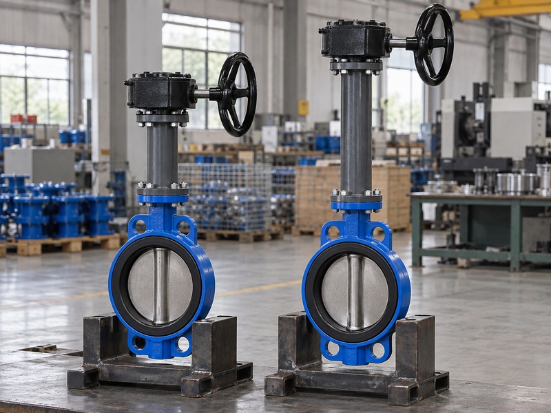
Mark the valve location, the required operating point and the obstructions between them. Include the finished floor or platform level and any pit cover that affects access. Record whether a person must use a wheel, operating key or another specified interface. The extension must fit the intended environment and allow the valve's maintenance procedure.
Check whether covers, insulation or nearby structures must be removed before the operator can be serviced. A location that works during construction can become obstructed once the plant is complete. For repeat installations, provide the actual site levels rather than using one extension length across different valve positions. Keep the selected access solution tied to the valve tag and approved layout revision.
- Mark finished operating levels.
- Include final insulation and covers.
- Check operation and maintenance access.
| Site condition | Input to provide |
|---|---|
| Pit or buried valve | Levels, cover and environment |
| Insulated pipe | Finished insulation envelope |
| Equipment obstruction | Required remote operating position |
3. How do you specify the extension length?
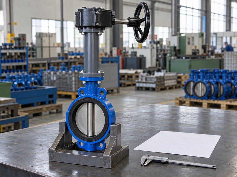
Specify a butterfly valve handwheel extension between named reference surfaces on the approved assembly drawing. Distinguish overall length from the distance between mounting faces or coupling engagement points. Include tolerances and installation levels, because two suppliers may use the same length term for different physical dimensions.
Which measurements should be confirmed before manufacture?
Show the valve mounting datum and the required location of the operator or input interface. Add the coupling engagement and any bracket thickness separately, so they do not disappear inside an ambiguous overall dimension. Check the installation with final pipe supports and floor levels in place. A butterfly valve handwheel extension mounted over a large assembly may also require a separate lifting and access review.
Do not cut a supplied extension or redrill coupling holes without an approved procedure. Those modifications can alter engagement, alignment and the protected exterior. Ask the supplier to state which dimension controls fabrication and which is provided for the installation envelope. Retain the approved drawing with the individual valve identification.
- Name the measurement datums.
- Separate engagement from exposed length.
- Approve dimensional changes before machining.
| Dimension | Meaning to define |
|---|---|
| Overall length | Outermost assembled limits |
| Mounting-face distance | Controlled support geometry |
| Engagement length | Coupling contact at each end |
4. How does extension length affect torsional movement?
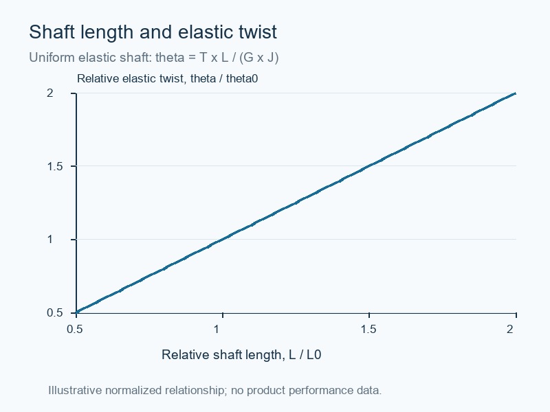
A butterfly valve handwheel extension twists elastically under transmitted torque, and a longer shaft generally twists more when its material and section remain unchanged. The amount depends on torque, length, shear modulus and polar second moment of area. This movement must be checked with the selected shaft design.
How should you interpret a torsion comparison?
For a uniform elastic shaft, twist follows the relationship theta equals torque multiplied by length, divided by shear modulus and polar second moment of area. A normalized comparison can show the effect of changing length while holding other inputs fixed. It cannot establish the allowable extension length or certify a supplied assembly. Solid and hollow shafts need the correct section calculation, and couplings add their own lost motion.
The design also needs strength, stiffness, fatigue and support checks appropriate to the service. Ask engineering to consider the operating torque range and the acceptable position error at the valve. A wheel that moves before the disc responds may reflect backlash, shaft twist or a loose connection, which require different corrective actions.
- Use the actual shaft section and material.
- Separate elastic twist from backlash.
- Confirm allowable movement for the application.
| Input | Effect to review |
|---|---|
| Length | Elastic twist and support span |
| Section geometry | Strength and torsional stiffness |
| Couplings | Engagement and lost motion |
5. How should you support the operator weight?
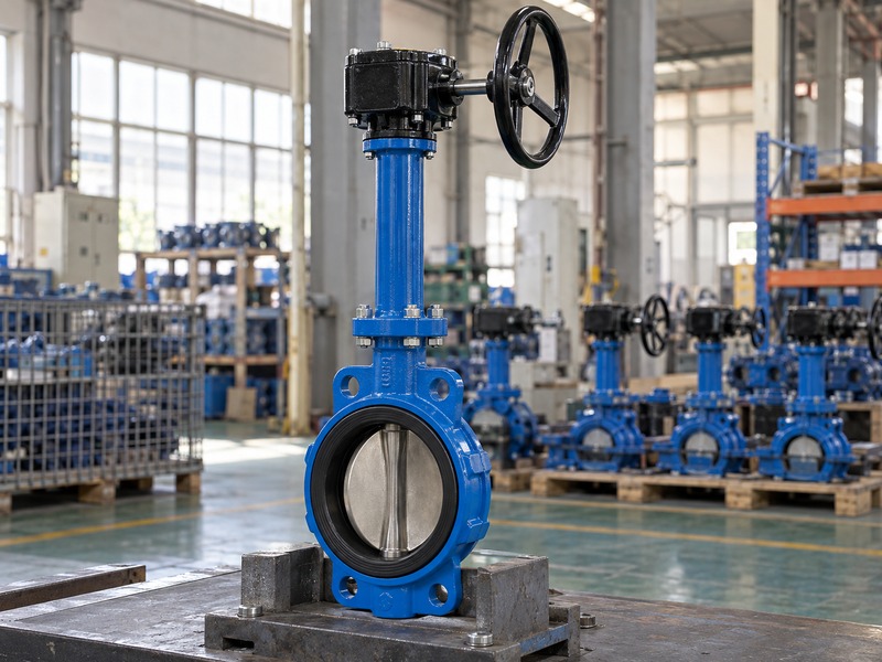
A butterfly valve handwheel extension needs an approved support arrangement that carries operator weight and external loads without overloading the valve stem. A structural outer tube, bearing arrangement or separate bracket may provide that load path. The selected design determines which parts carry torque and which carry weight.
What loads can a long extension introduce?
Consider the gearbox and wheel mass, handling loads, operating forces and any side load from misalignment. A tall assembly can also need support against vibration or accidental contact. Bearings and shoulders must be designed for their actual loads and environment. Adding a guide near the top can help alignment only if its position and attachment are correct.
A poorly located guide may force the shaft sideways and increase operating effort. Check the structural attachment and maintenance access with the equipment designer. Do not use pipe insulation, a pit cover or an improvised clamp as an assumed support. The supplier should identify the support points and any installation tolerances that the site must maintain.
- Define weight and side-load paths.
- Locate approved guides and bearings.
- Keep supports independent of insulation.
| Load | Part to identify |
|---|---|
| Operator weight | Structural support and bearing |
| Operating torque | Shaft and couplings |
| Side load | Alignment and guide arrangement |
6. What makes an extension coupling suitable?
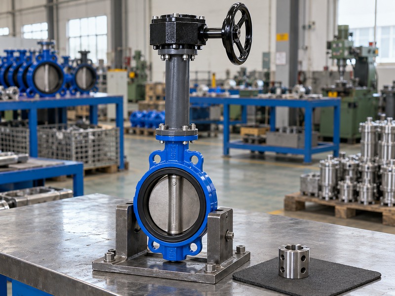
A butterfly valve handwheel extension coupling must transmit the specified torque while maintaining the approved engagement and alignment. Check its drive geometry, retention and installation access. A coupling that joins two shafts physically is not necessarily rated for the operating loads or suitable for the environment.
How do you avoid hidden assembly problems?
Show the connection at each end of the extension, including keys, pins, flats or other drive details. Confirm that retaining parts remain accessible after installation. Check for axial bottoming and inadequate engagement before tightening mounting faces. Do not use the fasteners to pull a misaligned assembly into place.
For a butterfly valve handwheel extension conversion, retain the valve manufacturer's allowable stem loads and mounting requirements. If a flexible coupling is proposed, ask what movement it permits and whether it changes the torsional response. Flexibility does not remove the need for alignment or support. Keep replacement couplings tied to the approved part specification so maintenance personnel can order the correct configuration later.
- Specify both end connections.
- Check engagement and axial position.
- Keep retention accessible for maintenance.
| Coupling check | Failure it helps prevent |
|---|---|
| Drive geometry | Slip or concentrated contact load |
| Retention | Unintended separation |
| Alignment | Binding and added side load |
7. Which environmental conditions need review?
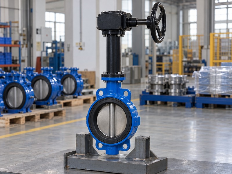
A butterfly valve handwheel extension must suit its external temperature, moisture, corrosion and contamination exposure. The extension's enclosure does not automatically share the valve's pressure or immersion rating. Ask for the actual protection and sealing arrangement for the specified installation.
How do buried and exposed installations differ?
A pit can collect water even when the process pipe carries a dry or clean fluid. Outdoor shafts can see rain, dust and temperature changes that differ from the valve's internal service. Identify any expected submergence, washdown or corrosive atmosphere before selecting bearings, seals and coatings. A protective tube may need drainage or another approved moisture strategy, depending on the design.
Avoid adding unapproved holes that compromise the specified enclosure. If insulation surrounds the valve, check temperature transfer toward the extension and operator rather than assuming distance alone provides thermal protection. RUITO's documented water-service applications still require a model-level review of the external operating arrangement and its actual site environment.
- State moisture and corrosion exposure.
- Confirm the actual enclosure protection.
- Review temperature at the operator location.
| Exposure | Review item |
|---|---|
| Pit water | Seals, bearings and permitted immersion |
| Outdoor weather | Coating and enclosure details |
| Hot equipment | Operator temperature and safe access |
8. How do you verify travel after fitting an extension?
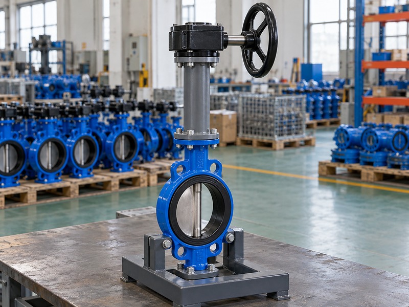
Check a butterfly valve handwheel extension against actual disc travel and the approved end positions during a controlled, isolated functional inspection. Verify the wheel direction, turns, indicator and stops. An upper indicator can appear correct even when a coupling is loose or the lower connection is assembled incorrectly.
What should the functional record distinguish?
Record the assembly identification and the conditions of the check. Compare movement in both directions and note any delay before the disc follows the input. Confirm that supports remain aligned throughout travel and that no part binds. Use the model-specific procedure for stop settings and final closure.
Do not use extra travel to force a damaged seat into sealing. Mechanical function, pressure-boundary integrity and seat leakage are separate inspection tasks. A smooth unloaded bench movement does not prove the operating effort at the maximum service differential pressure. Ask the supplier to state the torque-sizing basis and the acceptance tests for the complete extension assembly, with results linked to the same item and drawing revision.
- Compare input with actual disc travel.
- Record direction, turns and lost motion.
- Keep functional and pressure tests distinct.
| Check | Evidence |
|---|---|
| Travel correspondence | Input and disc positions agree |
| Support alignment | No binding through the stroke |
| Service capability | Approved sizing and test scope |
9. What belongs in an extension purchase package?
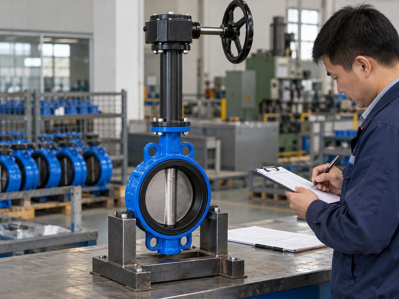
A butterfly valve handwheel extension purchase package should define duty, arrangement, reference dimensions, supports, environment and inspection. Include the valve and operator identification. This gives the supplier enough information to design the complete assembly rather than quoting a rod from length alone.
How do you control manufacture and delivery?
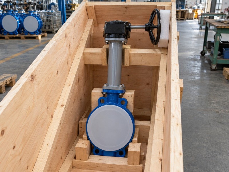
Freeze the assembly drawing after the site and supplier have resolved the operating level and support points. List the shaft, couplings, support tube, bearings, fasteners and operator as controlled parts. Agree which components arrive assembled and which site work remains necessary. The packing plan should support the valve body and the extension's structural parts while protecting the handwheel and shaft from transport loads.
Avoid lifting the assembly by the wheel or exposed operating shaft. For installation, provide the approved alignment and functional-check instructions with the shipment. If the site later changes the platform height or valve position, review the extension again before modifying the supplied parts. Keep the final installed arrangement in the maintenance record.
- Freeze the complete assembly revision.
- Define factory and site responsibilities.
- Support structural parts during transport.
| Purchase item | Required definition |
|---|---|
| Assembly | Valve, extension and operator arrangement |
| Installation | Datums, supports and alignment |
| Inspection | Travel, torque basis and test scope |
10. What do buyers ask about handwheel extensions?
Q1. Can I make an extension from an ordinary steel rod?
Only under an approved design. Torque, stiffness, couplings, supports, corrosion and retention must be checked for the complete assembly.
Q2. Does an extension increase the valve pressure rating?
No. It changes the operating arrangement. The valve's pressure-temperature rating and permitted differential pressure remain model-specific.
Q3. How do I know whether the gearbox can sit at the top?
Check the approved support and shaft design. The valve stem must not carry unintended gearbox weight or external side loads.
Q4. Can I shorten a supplied extension on site?
Obtain approval first. Cutting or redrilling can change engagement, alignment, coatings and the connection's load capacity.
Q5. What should I check if the wheel moves before the disc?
Check the approved procedure for backlash, coupling retention and shaft twist in a safely isolated condition. Do not compensate by forcing the wheel farther.
Provide the site levels, valve duty and required operating point when you contact us. RUITO can review the assembly arrangement and identify the extension details that need engineering approval.