
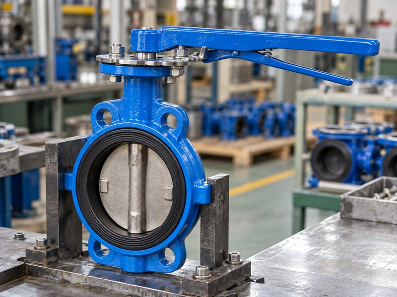
Fix butterfly valve lever orientation mistakes by checking full-stroke clearance, verified drive indexing, accessible locks, and approved manual operating limits. A lever that clears nearby equipment when closed may collide halfway through opening. Check the complete operating envelope against the model's instructions and accepted mounting drawing before installation or modification.
1. What makes butterfly valve lever orientation safe?
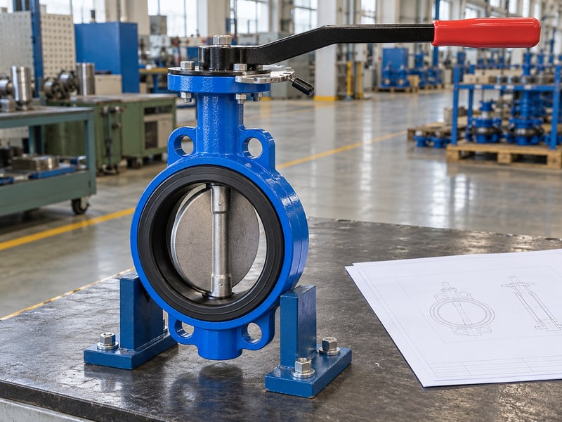
Butterfly valve lever orientation is safe for its intended duty when the approved assembly can complete its stroke without obstruction, excessive effort, or ambiguous indication. That review includes your operator's stance and hand space. A valve may fit between pipe flanges while its lever remains impractical to use.
Which references control the arrangement?
Start with the accepted assembly. Use the model-specific installation, operation and maintenance instructions and general arrangement drawing. These should identify the drive interface, lever length, plate position, and permitted mounting so layout decisions preserve the designed relationship between operator and disc.
- Confirm the exact valve and manual operator configuration.
- Locate both endpoints and the whole swept envelope.
- Check that a gloved hand can release and hold the lever.
What should a layout review capture?
Key takeaway: Review the installed operator as a moving assembly. Include the lever, release mechanism, hand clearance, and maintenance access in your layout record rather than checking a stationary outline alone.
| Layout element | Required review |
|---|---|
| Lever sweep | Unobstructed full stroke |
| Grip and release | Accessible operation |
| Drive and plate | Approved mounting relationship |
Mark the operating envelope on the drawing. Resolve conflicts before freezing the pipework layout.
2. How do you plan butterfly valve lever orientation clearance?
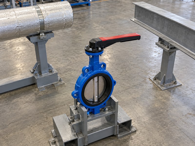
Butterfly valve lever orientation clearance should cover every position through the approved stroke plus the hand space needed for operation. Checking only fully open and fully closed positions can miss contact at an intermediate angle. Include the installed insulation, supports, instrument lines, and access barriers rather than reviewing bare pipes alone.
What belongs inside the clearance study?
Check the moving envelope. Use the actual lever dimensions and mounting height from the accepted drawing. In compact wafer butterfly valve installations, reduced face-to-face length can help the piping layout while leaving the lever's external swing requirement unchanged.
- Plot the hub, grip, release trigger, and locking accessories.
- Include permanent insulation and removable service covers.
- Check overlap with the operating space of adjacent valves.
How should you record a clearance conflict?
Key takeaway: A usable gap must remain available throughout the stroke. Record the nearest obstruction, the position where contact occurs, and the access required so engineering can compare permitted arrangements before assembly changes.
| Conflict | Design response to review |
|---|---|
| Pipe contact | Approved mounting or layout change |
| Restricted hand space | Revised access arrangement |
| Adjacent lever overlap | Operating envelope coordination |
Verify the final arrangement on site. Recheck after insulation and surrounding equipment are installed.
3. Can butterfly valve lever orientation change disc indication?
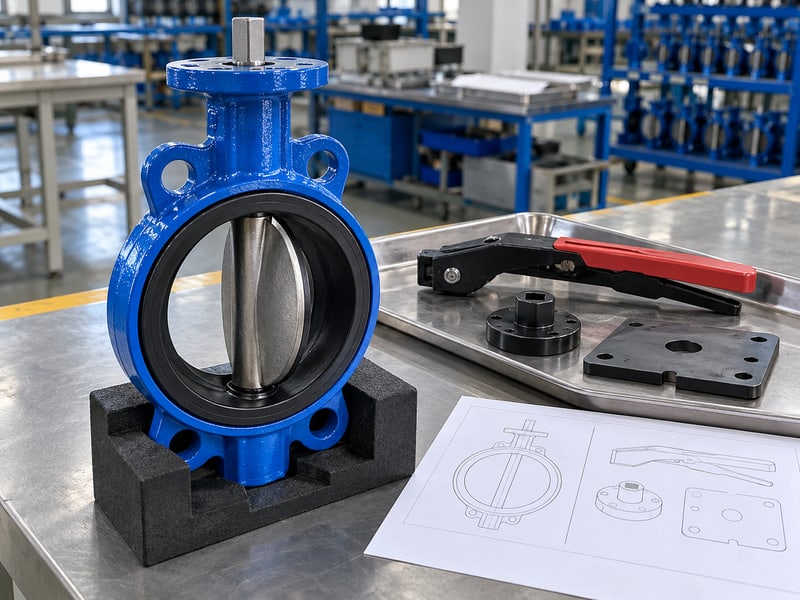
Butterfly valve lever orientation can change the visible indication if an operator is repositioned without preserving its approved indexing. A direct lever commonly aligns with the pipe when open, but that reading applies only after the drive relationship has been verified. Alternative arrangements need their own documented reference.
How do you preserve the position reference?
Confirm the drive before relabelling. Compare the hub, shaft interface, and position plate with the assembly instructions. A new painted arrow cannot correct a wrongly engaged hub, and a lever that points in a convenient direction may place the disc somewhere else.
- Identify the approved disc reference and shaft feature.
- Verify both endpoints under authorized conditions.
- Check that labels agree with the confirmed assembly.
What should operators use after a change?
Key takeaway: Read the verified local reference for that valve. Keep the accepted mounting drawing and an installation photograph available so another operator can distinguish an approved alternative from an assembly error.
| Reference | Use |
|---|---|
| Lever direction | Position indication after verification |
| Shaft feature | Disc reference where documented |
| Accepted drawing | Permitted assembly arrangement |
Update local instructions after an approved change. Treat any disagreement between references as an unresolved condition.
4. What does butterfly valve lever orientation mean for detents?

Butterfly valve lever orientation must keep the release mechanism and detent plate aligned so the latch engages the intended positions. A notch provides a mechanical holding location, not a measured flow setting. The number, spacing, and permitted use of those positions depend on the supplied operator assembly.
How do you check plate engagement?
Inspect the latch contact. Look for full engagement where the instructions require it, unobstructed release movement, and correctly retained plate hardware. Establish isolation before adjusting the plate or removing parts, since a disengaged lever may move under disc torque or accidental handling.
- Match the plate and latch with the approved parts arrangement.
- Check for worn edges, distortion, corrosion, or trapped debris.
- Verify that required positions can be selected and retained.
How should intermediate detents be described?
Key takeaway: A detent identifies an angular setting whose suitability needs a separate duty review. Confirm the valve's permitted regulating service before using an intermediate notch as a long-term operating position.
| Detent feature | Check |
|---|---|
| Latch contact | Correct engagement |
| Release travel | Free movement and access |
| Intermediate notch | Approved duty and holding capacity |
Replace damaged parts through the approved maintenance procedure. Record the position reference after reassembly.
5. How does butterfly valve lever orientation affect locking?
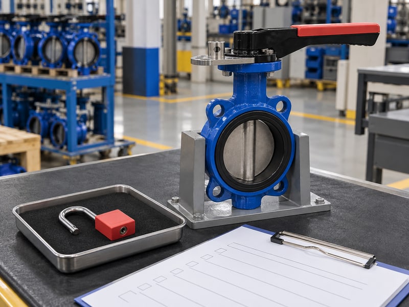
Butterfly valve lever orientation affects locking by determining whether the approved locking feature remains accessible at the required position. A padlock that fits a hole may still obstruct the release mechanism or nearby equipment. Specify the intended locking function before selecting the operator arrangement.
Which locking function do you need?
Define the required restraint. A detent latch holds a selected position, while an approved lock arrangement may restrict unauthorized operation. Your site's energy-isolation procedure determines whether that arrangement is suitable for a particular maintenance boundary; a locked lever alone cannot prove seat tightness or absence of trapped pressure.
- Identify the position that must be secured.
- Confirm approved lock dimensions and access with gloves.
- Check that the lock cannot obstruct required operator travel.
What should an acceptance check include?
Key takeaway: Verify locking with the actual accessory and installed surroundings. Record its purpose, permissible position, and release method so purchasing and operating teams share the same requirement.
| Locking concern | Acceptance check |
|---|---|
| Access | Lock can be fitted and removed |
| Restraint | Approved parts secure the intended position |
| Work boundary | Site isolation procedure is satisfied |
Specify locking requirements in the inquiry. Confirm the final arrangement before handing over the valve.
6. What limits butterfly valve lever orientation and manual effort?
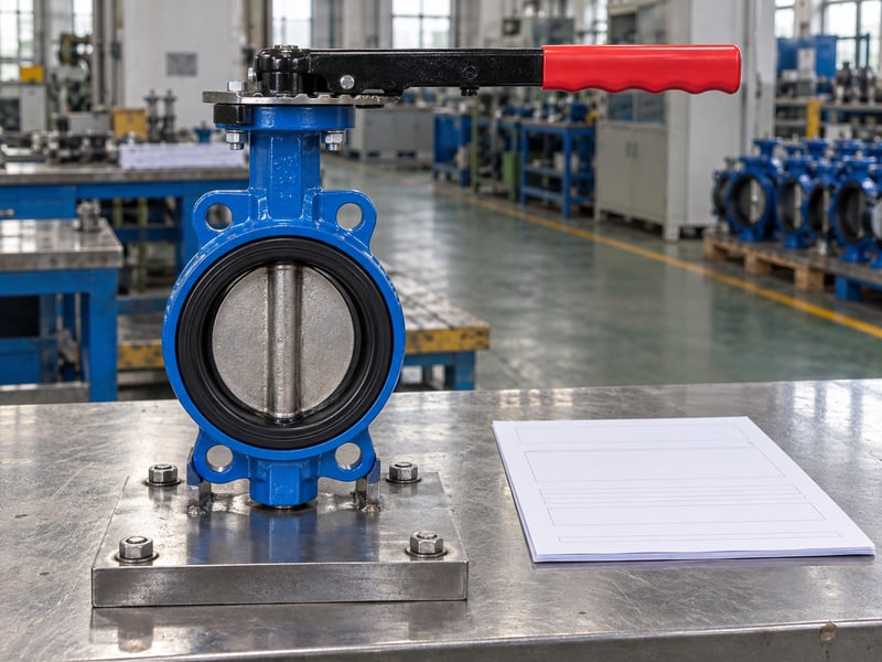
Butterfly valve lever orientation is constrained by available grip access, permissible hand force, and the valve's service torque. Required torque depends on valve geometry, seating condition, temperature, and differential pressure. Nominal pipe size alone does not establish whether direct lever operation is suitable.
How should manual suitability be checked?
Match effort with service torque. Use the manufacturer's breakaway, running, and seating torque information for the actual conditions. Effective lever radius and force direction affect available torque, so a partly accessible grip can make a nominally adequate operator unsuitable at its installed location.
- Confirm maximum service differential and temperature.
- Use the specified lever and permissible operating effort.
- Review another operator where manual effort exceeds approved limits.
What should you do with unexpected resistance?
Key takeaway: Increasing force without diagnosis can overload the drive or damage the seat. Stop at the approved limit and report the valve position, conditions, and where resistance begins rather than adding an extension pipe.
| Manual operation factor | Required information |
|---|---|
| Valve resistance | Service-specific torque |
| Available grip | Effective radius and access |
| Allowable effort | Approved operator limit |
Request an operator selection review if effort is excessive. Keep improvised extensions out of the operating procedure.
7. How should butterfly valve lever orientation stops be set?
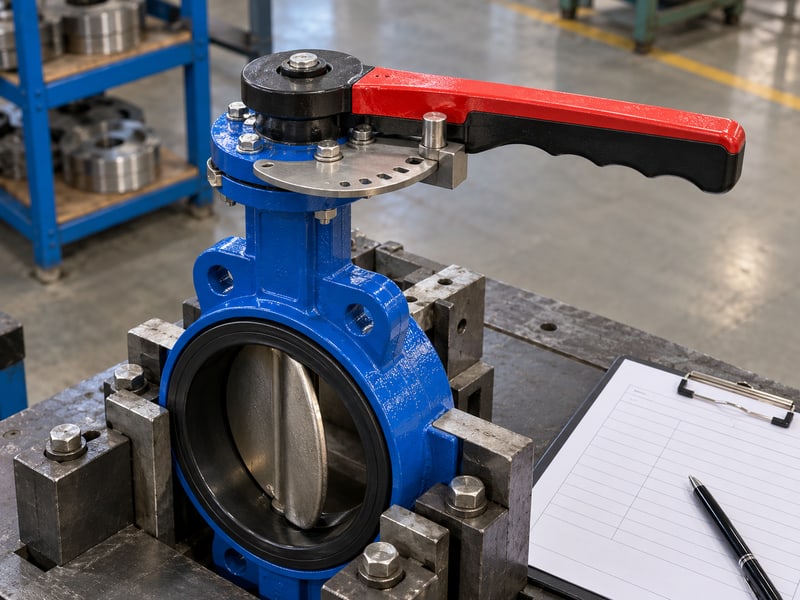
Butterfly valve lever orientation stops should match the model's specified disc endpoints and setting procedure. A visible handle direction is insufficient for setting closure, and harder stop contact does not establish better sealing. The instructions must determine which parts limit travel and whether field adjustment is permitted.
What should be checked before adjustment?
Identify the designed travel limit. Some assemblies establish endpoints through plate geometry or fixed operator features rather than an adjustable stop. Isolate and depressurize before changing hardware, then follow the model-specific method for confirming disc travel without introducing seat overload or excessive rotation.
- Identify fixed and adjustable features in the instructions.
- Confirm the specified disc reference before setting endpoints.
- Check retention and indication after authorized adjustment.
How does the pipe connection affect this work?
Key takeaway: Endpoint verification must also account for installed disc clearance. A lug butterfly valve still requires its own approved pipe interface and clearance review, even when the lever plate appears correctly set.
| Stop review | Acceptance basis |
|---|---|
| Open endpoint | Documented disc travel |
| Closed endpoint | Model-specific seating position |
| Final assembly | Retained hardware and correct indication |
Retain the accepted settings with the maintenance record. Investigate incomplete travel before altering a stop.
8. Can butterfly valve lever orientation suit tight plant rooms?
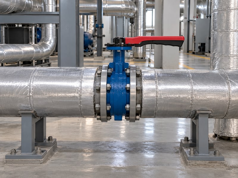
Butterfly valve lever orientation can suit a tight plant room when the full sweep and operator access fit an approved arrangement. A lever tucked behind a pipe may look compact while requiring an unsafe reach. Assess routine operation, lock removal, and maintenance together rather than accepting clearance for installation alone.
Which access conditions need a site check?
Review the operator's working position. Check whether staff can see the indication, release the latch, and complete the stroke without leaning over hot surfaces or standing on piping. For HVAC and district energy installations, include insulation, condensate conditions, and access around equipment scheduled for servicing.
- Verify stable standing space and a usable grip.
- Check clearance with normal protective clothing and gloves.
- Preserve access for approved operator removal and replacement.
When should another operator be considered?
Key takeaway: Restricted access may justify a different approved drive or a revised layout. Compare its torque capability, space requirements, and indication before replacing a lever, since each operator changes the access problem.
| Site restriction | Review option |
|---|---|
| Blocked sweep | Layout or permitted mounting change |
| Excessive reach | Revised operating access |
| High torque | Appropriate geared or powered operator |
Photograph the installed restrictions from the operating position. Submit dimensions with the proposed alternative for engineering review.
9. How do you inspect butterfly valve lever orientation in service?
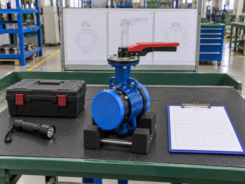
Butterfly valve lever orientation should be inspected for changes in clearance, indication, latch engagement, and operating condition within the site's maintenance program. New insulation or relocated supports can obstruct an arrangement that previously worked. Corrosion and worn operator parts can also reduce the usefulness of its position reference.
Which observations should be recorded?
Compare against the accepted condition. Use the verified installation photograph and drawing to identify movement or changed parts. Functional operation needs process authorization; adjustment, disassembly, or replacement requires the applicable isolation and maintenance procedure rather than an informal check on live equipment.
- Record damage, looseness, unreadable marks, and access changes.
- Note latch engagement and any reported change in effort.
- Identify the operating conditions associated with abnormal resistance.
How should inspection frequency be chosen?
Key takeaway: Use service conditions, operation frequency, observed wear, and manufacturer guidance to set inspection intervals. Repeat the position and clearance review after operator work or changes around the valve so the accepted baseline stays useful.
| Trigger | Review focus |
|---|---|
| Operator replacement | Indexing, retention, and indication |
| Layout modification | Sweep and access |
| Changed operating effort | Loads and assembly condition |
Assign corrective work to identified findings. Close each issue with an accepted condition or a documented restriction.
10. What butterfly valve lever orientation details aid selection?
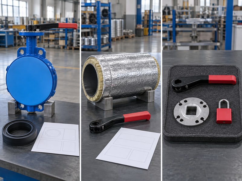
Butterfly valve lever orientation selection needs the valve duty, required manual effort, mounting interface, operating envelope, and locking function. These inputs let engineering compare a direct lever with other approved operators. A photograph of available space helps, but dimensions and service conditions are needed before confirming a configuration.
What should your technical inquiry include?
Describe the operating requirement. RUITO can review the selected valve structure, drive interface, and documentation for an agreed assembly. Send the highest closing differential rather than only the nominal pressure class, because the difference across the disc influences the torque required during operation.
- Valve size, connection, materials, and available identification.
- Medium, temperature, differential pressure, and operation frequency.
- Clearance dimensions, locking needs, and required manual access.
What should an accepted proposal provide?
Key takeaway: Request a mounting drawing and operating limits for the complete assembly. For lever selection, clearance review, and configuration documentation, contact us today with your operating conditions and layout information.
| Selection input | Requested confirmation |
|---|---|
| Service loads | Manual operator suitability |
| Space and access | Accepted operating envelope |
| Locking requirement | Approved mechanism and position |
Collect the layout dimensions before requesting parts. Identify which mounting details need confirmation on the proposed drawing.
FAQ
Q1: Can I fit a longer lever when operation feels heavy?
Only if the manufacturer approves it. Extra length can exceed allowable shaft, hub, or operator loads, so investigate torque and service conditions before changing parts.
Q2: What's the best way to check sweep clearance?
Check the whole approved stroke. Include the grip, release mechanism, lock, insulation, and hand space rather than comparing only open and closed endpoints.
Q3: Can I rotate the detent plate for better access?
Only through an approved arrangement. Isolate before adjustment and verify the plate, drive indexing, travel limits, and disc reference after reassembly.
Q4: Does locking the lever prove isolation?
No. Locking restricts movement according to its approved design; safe maintenance also requires the site's isolation and pressure-verification procedure.
Q5: How do I know if direct lever operation is unsuitable?
Compare service torque, allowable hand effort, and installed access. Request another approved operator when these requirements cannot be met with the specified lever.