
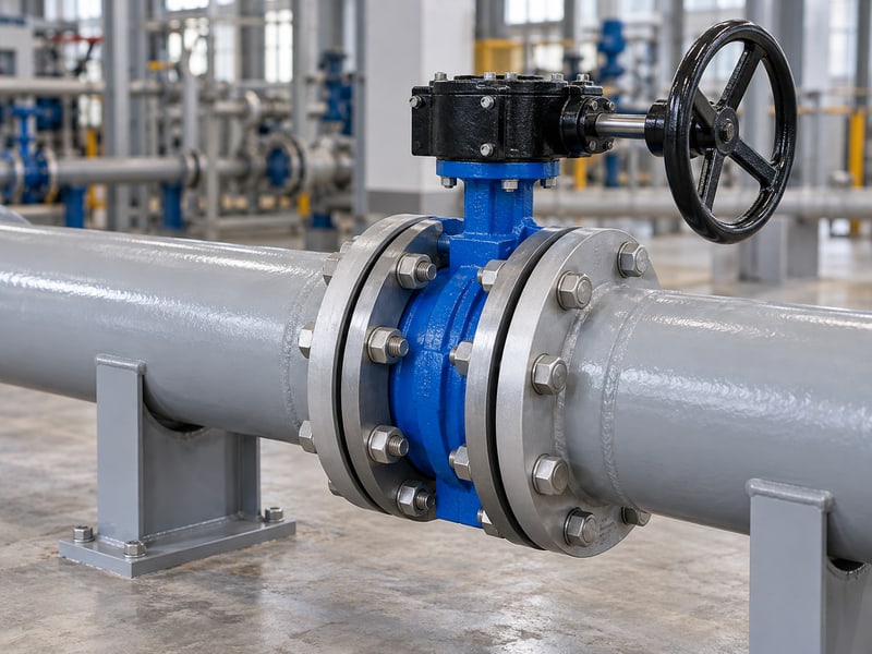
Fix butterfly valve orientation mistakes by confirming pressure direction, permitted shaft position, and piping layout against the supplied model's documents. A replacement may fit existing flanges yet face the wrong pressure side or disturb pump inlet flow. Check the approved drawing and installation manual before reserving a shutdown.
1. What determines butterfly valve orientation?
Butterfly valve orientation depends on three separate decisions: which body face receives pressure, where the shaft lies, and where the valve sits beside other equipment. A convenient handle position cannot settle all three. Review each decision against the actual operating and shutdown conditions.
Which drawing should you use?
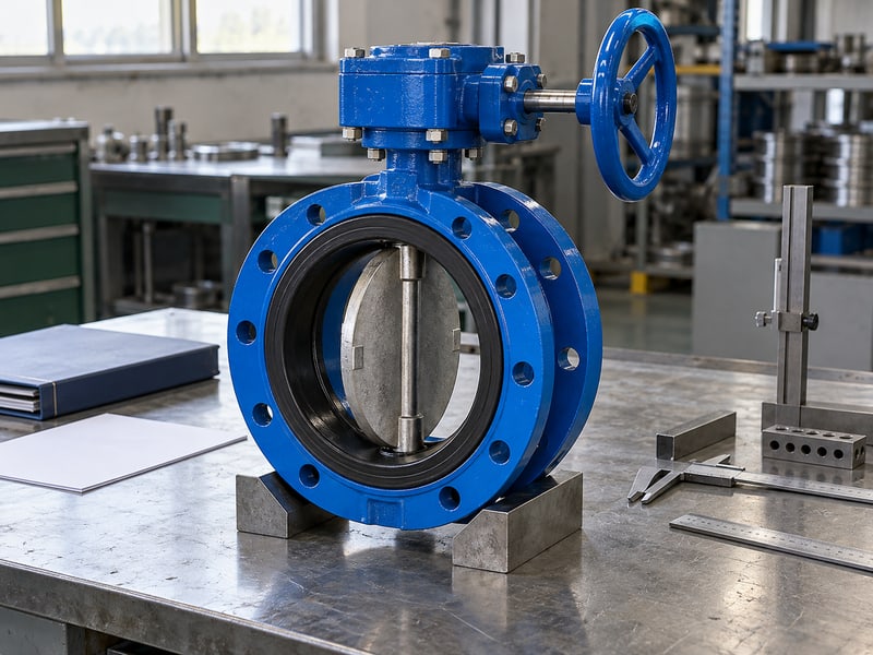
Use the drawing for the supplied valve size, seat, and drive assembly. A catalogue illustration may show another connection or actuator position, while a piping diagram usually omits the disc's full travel envelope. Compare the equipment tag with the nameplate before applying either document.
- Identify normal flow and possible reverse pressure.
- Mark the shaft axis on the piping elevation.
- Show nearby elbows, pumps, reducers, and supports.
Keep pressure direction and shaft position separate. You can rotate some bodies around the pipe axis without reversing their pressure faces. Turning a directional valve end for end changes a different condition and needs its own approval.
How do you record the decision?
Draw an upstream face label, a shaft centerline, and an operator access envelope on the approved layout. Key takeaway: a recorded three-part orientation prevents a visually plausible installation from passing an incomplete review.
| Decision | Record |
|---|---|
| Pressure side | Approved upstream face |
| Shaft position | Axis on elevation |
| Equipment layout | Clearance and spacing |
Resolve missing labels before releasing the installation drawing.
2. How does pressure affect butterfly valve orientation?
Butterfly valve orientation must match the approved shutoff differential in each pressure direction. Line pressure alone does not describe the load across a closed disc. A drained downstream pipe can create a larger differential than the same system produces during normal circulation.
What happens across a closed disc?
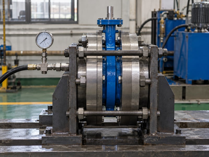
Pressure loads the disc, shaft, bearings, and seat together. Seat geometry determines how that load changes sealing contact, while the drive must provide the required opening and closing torque. Avoid a blanket claim that pressure always assists sealing or always reduces opening effort.
- State maximum upstream pressure with downstream empty.
- Include reverse pressure during shutdown or backfeeding.
- Check temperature at the limiting pressure condition.
Size against the closed differential. An actuator selected from normal running pressure can lack torque when a valve must open against an isolated line. Request the model's torque data for the specified differential and pressure direction.
What should procurement compare?
Compare directional seat ratings, pressure-temperature limits, and operating torque on the same configuration. Keep factory proof pressure separate from allowable working pressure. Key takeaway: the largest permitted closed differential governs the orientation review and drive calculation.
| Condition | Information needed |
|---|---|
| Normal isolation | Forward differential |
| Backfeeding | Reverse differential |
| Elevated temperature | Applicable working limit |
Add both pressure directions to the valve datasheet.
3. Are flow arrows enough for butterfly valve orientation?
Butterfly valve orientation needs an interpreted arrow plus the model's instructions and ratings. A marking may identify preferred flow, permitted pressure direction, or another installation requirement. You should confirm its meaning rather than treating every arrow as an identical instruction.
What if the marking is unclear?
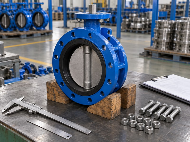
Photograph the body marks and nameplate, then ask the supplier which face must receive the specified pressure. A missing arrow does not establish bidirectional capability. Neither does a symmetric-looking body prove equal seat ratings in both directions.
- Read the marking description in the installation manual.
- Match the serial or product identification with supplied records.
- Obtain clarification where arrows and drawings disagree.
Confirm the arrow's meaning before bolting up. Paint, insulation, or an old field label can hide or misrepresent an original mark. Clean the marking area using an approved method without damaging identification plates or protective coatings.
How can operators retain that information?
Record the confirmed pressure face in the handover package and use a visible site label where permitted. Key takeaway: an arrow becomes useful installation evidence after its meaning is tied to the exact valve.
| Finding | Required response |
|---|---|
| Clear documented arrow | Follow its stated meaning |
| Missing marking | Request model confirmation |
| Conflicting documents | Close the discrepancy |
Stop installation at the marking check if evidence conflicts.
4. How do offsets change butterfly valve orientation?
Butterfly valve orientation for an offset design requires its own directional seat and torque data. Offsets change how the disc approaches and leaves the seat. Those geometric differences do not create a universal installation rule for every double-offset or triple-offset valve.
What does geometry tell you?
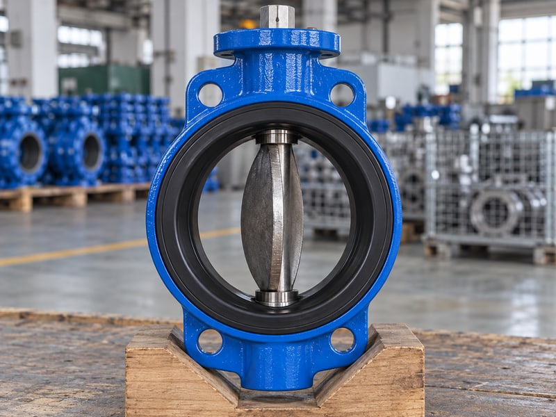
A concentric design places its shaft near the disc and bore centerlines; offset designs displace axes and may use an inclined sealing geometry. The resulting contact pattern depends on the seat construction. Treat offset count as a design description, then verify the declared pressure and leakage limits.
- Identify concentric or offset construction from the section drawing.
- Confirm the seat material and retaining arrangement.
- Request separate reverse-pressure limits where applicable.
Check the seat rating before choosing a face. RUITO's flanged butterfly valve options include concentric and double-eccentric configurations. Match their individual documents with your required direction instead of transferring one arrangement's rating across the range.
What changes during replacement?
An offset replacement may need another pressure face or torque allowance despite matching bore and drilling. Compare its opening envelope and pressure-side instruction. Key takeaway: matching flange dimensions does not establish equivalent directional performance.
| Design detail | Verify separately |
|---|---|
| Offset geometry | Disc opening envelope |
| Seat construction | Directional shutoff |
| Drive assembly | Opening and closing torque |
Request a section drawing with the replacement proposal.
5. Which shaft suits butterfly valve orientation?
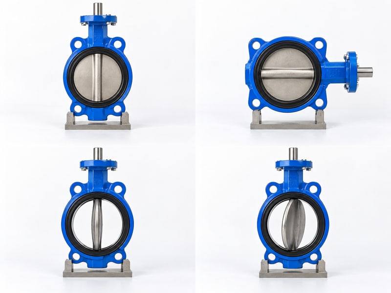
Butterfly valve orientation may permit a horizontal, vertical, or other shaft position only within the model's installation limits. Gravity, bearing arrangement, sediment, and attached drive weight can affect that choice. Available space does not establish permission for an inverted assembly.
What should you compare on site?
Start with the permitted positions, then inspect access for operation, drainage, and maintenance. In a horizontal pipe, rotating the body changes shaft elevation without changing the pipe's flow direction. In a vertical pipe, shaft position and upstream face still need separate checks.
- Allow room for the full operator movement.
- Keep service points accessible after insulation.
- Review sediment around the lower shaft penetration.
Review the whole assembly's allowed position. A bare valve body's permitted mounting position may differ from the restrictions of its gearbox, actuator, or accessories. Ask for approval of the supplied assembly rather than relying on a statement about the body alone.
How should a constrained layout be resolved?
Send an elevation with obstructions, maintenance space, and proposed extensions marked. Reorienting the operator may solve access if the mounting design allows it. Key takeaway: choose shaft position from approved mechanical limits before arranging convenient controls.
| Constraint | Review |
|---|---|
| Low ceiling | Drive removal space |
| Sediment service | Lower bearing exposure |
| Inverted proposal | Assembly approval |
Get the constrained mounting position confirmed before purchasing.
6. What does a pump change in butterfly valve orientation?
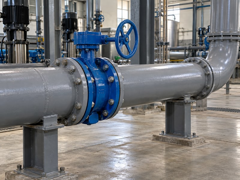
Butterfly valve orientation beside a pump must follow both valve and pump layout requirements. A disc near the suction inlet can disturb the approaching flow and add head loss. No single shaft alignment or straight-run distance suits every pump, disc profile, and inlet arrangement.
What belongs in the hydraulic review?
Supply normal and maximum flow, available suction pressure, fluid temperature, and the complete inlet layout. Include reducers, strainers, elbows, and other sources of loss. Check the pump's required inlet conditions and cavitation margin across the intended operating range.
- Identify whether the valve provides isolation or throttling.
- State its normal operating disc position.
- Obtain the pump supplier's spacing and alignment requirements.
Treat suction throttling as a separate design decision. Partly closing a suction valve increases loss and can reduce available inlet pressure. A shaft-position change cannot correct an inadequate suction-pressure margin or an unsuitable valve operating point.
How do you handle a compact pump skid?
Show actual distances on the skid drawing. Where spacing falls short, assess a revised layout or supplier-approved alternative. Key takeaway: pump inlet quality requires a system check, including valve loss and nearby fittings.
| Input | Purpose |
|---|---|
| Flow range | Evaluate inlet distortion |
| Suction pressure | Check cavitation margin |
| Actual layout | Confirm approved spacing |
Submit the complete suction arrangement with the valve enquiry.
7. How do elbows affect butterfly valve orientation?
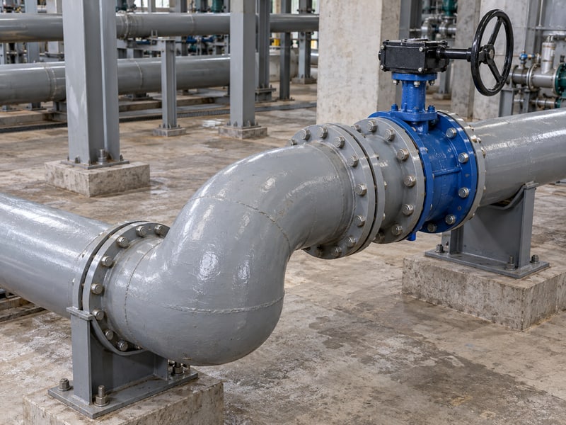
Butterfly valve orientation near an elbow needs a layout-specific assessment of distorted flow and disc loading. An elbow can produce an uneven velocity profile downstream. The outcome depends on its geometry, distance from the valve, disc angle, and additional upstream fittings.
Which dimensions should you supply?
Give the elbow radius, bend plane, pipe diameter, and face-to-fitting distance. Include plan and elevation views to capture bends in different planes. Avoid universal instructions about placement or shaft alignment.
- Mark the bend plane and proposed shaft centerline.
- Show adjacent bends, branches, and reducers.
- State whether continuous throttling is expected.
Draw the bend plane before discussing alignment. Phrases such as “parallel to the elbow” can mean different things to site staff. Use an annotated drawing so the reviewer can specify a shaft axis without ambiguous verbal directions.
What if the existing spacing cannot change?
Ask the valve supplier to evaluate the intended operating range and uneven loading for that arrangement. Persistent vibration may require changes beyond shaft rotation, including valve selection or piping layout. Key takeaway: elbow guidance becomes actionable when the actual geometry and operating duty are provided.
| Layout item | Record |
|---|---|
| Bend plane | Plan and elevation |
| Valve distance | Actual measured spacing |
| Operating duty | Isolation or throttling |
Annotate the existing spool before requesting a layout recommendation.
8. How do solids influence butterfly valve orientation?
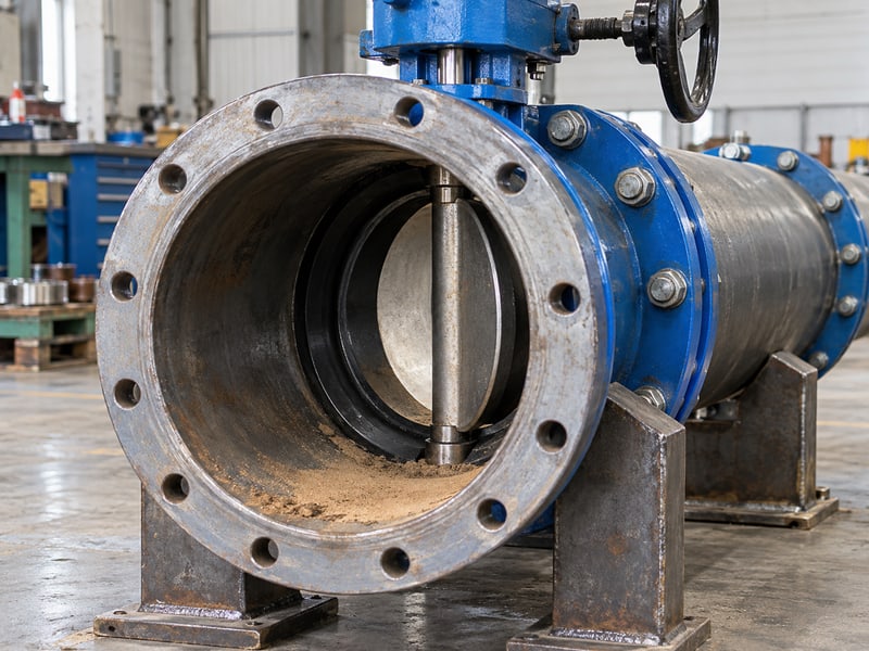
Butterfly valve orientation can reduce some sediment exposure when the manufacturer approves the proposed shaft position. It cannot make an unsuitable valve handle abrasive particles or long fibers. Select the valve around the actual solids content before deciding how its shaft should sit.
What should process staff describe?
Document particle size, hardness, concentration, fibers, and settlement. Distinguish clarified process water from sludge. RUITO's water and wastewater application information helps frame the enquiry; the selected configuration needs its own media review.
- Identify material that could lodge at the seat.
- Explain flushing and expected idle periods.
- Confirm access for inspecting deposits safely.
Resolve solids compatibility before changing the shaft. A horizontal shaft may avoid a lower shaft penetration in certain approved arrangements. Disc movement, seat contact, and local flow still determine whether debris can accumulate or interfere with closure.
Which operating practice belongs in the plan?
Where the model and process permit, define a flushing or exercising procedure with safe isolation and discharge arrangements. Do not force a disc through a suspected obstruction using additional handle length. Key takeaway: orientation supports an approved solids-handling plan but cannot replace appropriate valve selection.
| Media issue | Check |
|---|---|
| Settling particles | Deposit locations |
| Hard particles | Seat and disc damage risk |
| Fibers | Disc obstruction risk |
Provide a solids description with the process datasheet.
9. What access limits butterfly valve orientation?
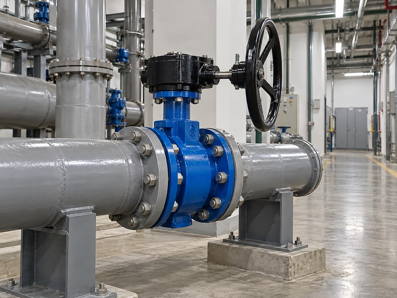
Butterfly valve orientation must allow safe operation, inspection, and removal of the installed assembly. A body position that clears the pipe can still block a gearbox cover or actuator lift path. Review finished conditions, including insulation, platforms, drains, and cable trays.
What must stay reachable?
Identify manual controls, indicators, fasteners, and service points. Check that staff can read the tag and operate from a stable position. Reserve removal space according to the assembly drawing.
- Show handwheel or lever movement in both end positions.
- Leave access for approved lifting equipment.
- Keep instruments and wiring outside the moving envelope.
Check maintenance space with the insulation fitted. Temporary construction access can disappear after adjacent trades complete their work. A layout review should include the equipment as it will stand during operation, with guards and permanent platforms installed.
What should the support design address?
Support the pipe and any heavy operator through an approved load path without pulling the valve body out of alignment. Mounting hardware and brackets need to account for the actual assembly weight and operating reaction. Key takeaway: usable access and controlled support loads belong on the same orientation drawing.
| Envelope | Verify |
|---|---|
| Operation | Full control movement |
| Inspection | Visible tag and indicator |
| Maintenance | Tool and removal space |
Walk through the finished layout with operations staff before approval.
10. How do you approve butterfly valve orientation?
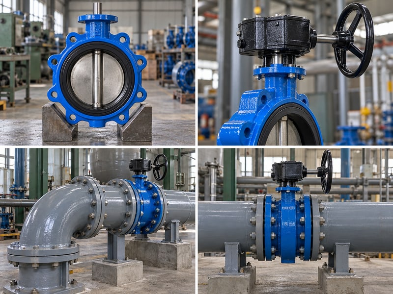
Butterfly valve orientation is ready for approval when direction, shaft position, hydraulic layout, and service access have documented answers. Record unresolved deviations before site work begins. The installation and commissioning records should identify the same valve and approved arrangement.
What goes into the handover package?
Include the approved layout, model manual, directional ratings, and inspection records. Note special pump spacing, elbow alignment, support, or solids conditions. Close each deviation against the supplied model. Replacement staff need a reproducible arrangement.
- Record body pressure face and permitted shaft position.
- Retain clearance and support details.
- List the operating limits and commissioning checks.
What is the next procurement step?
Send RUITO your medium, temperature, pressure in both directions, maximum closed differential, and annotated layout. The team can review the valve configuration and installation documents against those inputs. Key takeaway: approve a documented arrangement that maintenance staff can verify; contact us today with the drawing and operating conditions.
| Approval item | Evidence |
|---|---|
| Valve direction | Model rating and marking |
| Shaft and access | Approved assembly drawing |
| Hydraulic layout | Pump and valve review |
Attach the approved orientation drawing to the purchase specification.
Frequently asked questions
Q1: Can I install every butterfly valve either way?
No. The exact model must have the required directional shutoff rating for your pressure and temperature.
Q2: Can I turn the shaft horizontal?
Only if the supplied assembly permits that position. Check bearings, drive restrictions, sediment, and support.
Q3: How do I know what a body arrow means?
Read its definition in the model manual. Ask the supplier if markings or drawings conflict.
Q4: What's the best distance from a pump?
Use the pump and valve suppliers' requirements for your layout. A universal pipe-diameter rule is insufficient.
Q5: Can changing orientation cure vibration?
Sometimes an approved change helps. Review flow, differential pressure, supports, and nearby fittings before changing the installation.