
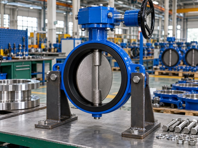
Fix butterfly valve stem orientation mistakes by checking the shaft axis against approved mounting positions, bearing loads, deposits, and drive support. A cramped layout may favor a position the assembly cannot accept. Review the section drawing, fluid conditions, and maintenance envelope before freezing the piping design.
1. What is butterfly valve stem orientation?
Butterfly valve stem orientation describes the shaft axis relative to gravity, the pipe, and nearby equipment. The stem transmits operating torque and locates the disc through its supporting components. Its position should be stated on a drawing rather than described only as “valve upright.”
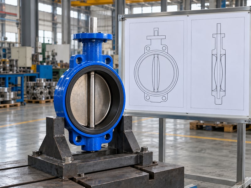
Which axis are you specifying?
Distinguish the pipe centerline from the shaft centerline and the body's pressure faces. A horizontal pipe can contain a valve with a horizontal or vertical shaft if the model permits those positions. Rotating the body around that pipe changes the shaft position without exchanging upstream and downstream faces.
- Mark the shaft centerline in plan and elevation.
- Identify gravity direction on the arrangement.
- Show the drive and bearing locations.
Specify the shaft axis on the drawing. Instructions such as “turn the valve sideways” leave the rotation and resulting pressure face unclear. A marked elevation lets the installer and reviewer confirm the same physical arrangement.
How does that help replacement work?
Record the approved position, valve identification, and drawing revision. Photograph drives and supports before insulation hides body features. Key takeaway: an explicit shaft axis prevents maintenance crews from reconstructing orientation through guesswork.
| Reference | Record |
|---|---|
| Pipe centerline | Flow-path axis |
| Shaft centerline | Disc rotation axis |
| Gravity direction | Vertical reference |
Add all three references to the installation elevation.
2. Is horizontal butterfly valve stem orientation permitted?
Butterfly valve stem orientation may be horizontal when the exact valve and drive assembly permit it. This position changes how gravity loads the disc and shaft supports. A general statement that butterfly valves mount in any position is insufficient for an assembled valve package.
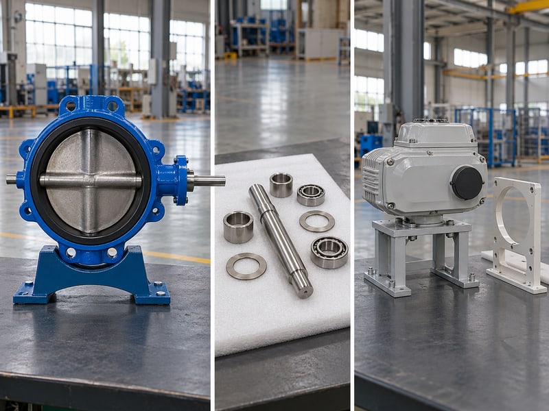
What needs checking mechanically?
Review bearings, shaft retention, disc weight, and drive restrictions. Confirm support requirements for a side-mounted operator. Bare-body mounting permission does not cover every attached drive or extension.
- Confirm horizontal mounting in the model IOM.
- Check required support for the installed drive weight.
- Allow access to both shaft ends where service requires it.
Approve the complete assembly's position. An installer may choose a horizontal shaft to improve handwheel reach, yet the operator's weight can create an unsupported load. Supply the proposed drive location and support drawing with the mounting enquiry.
When might you prefer this arrangement?
An approved horizontal shaft can reduce exposure of a lower shaft penetration to settling deposits in some services. That benefit depends on the actual valve construction and medium. Key takeaway: a horizontal position is a reviewed mechanical option whose suitability depends on bearings, deposits, and attached equipment.
| Check | Required answer |
|---|---|
| Valve mounting | Position permitted |
| Drive mounting | Position permitted |
| External support | Defined load path |
Request written confirmation for the proposed side-mounted assembly.
3. Is vertical butterfly valve stem orientation permitted?
Butterfly valve stem orientation may be vertical when the model accepts the resulting axial and bearing loads. A top-mounted drive often provides convenient access, but convenience does not establish mechanical suitability. Inverted mounting requires a separate check of the complete assembly's restrictions.
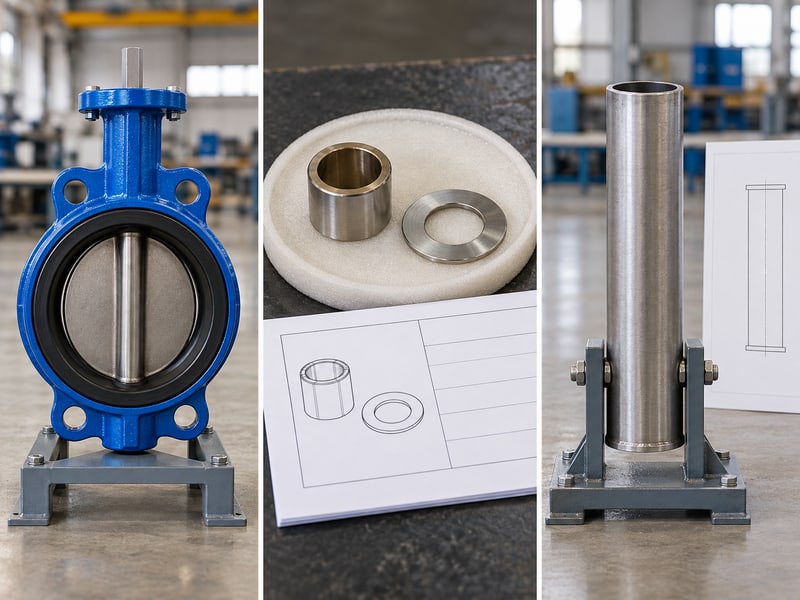
Where does disc weight go?
Supports carry gravity and operating loads. Thrust washers, bearings, or other retaining components control axial location according to construction. The section drawing identifies components; approved model limits establish suitability.
- Identify the permitted top and bottom orientation.
- Check retention and bearing instructions.
- Review access around the lower shaft seal or plug.
Check the lower shaft area for deposits. In a horizontal pipe, a vertical shaft can place one penetration near the pipe invert. Settling material around that region may affect inspection or wear, so review the medium before accepting the arrangement.
What changes in a vertical pipe?
The shaft usually crosses a vertical flow path in a horizontal plane, making phrases such as “vertical valve” ambiguous. Specify pipe and shaft axes separately and retain pressure direction on the drawing. Key takeaway: mounting descriptions should identify the actual shaft axis and gravity load rather than the pipe's appearance.
| Description | Better specification |
|---|---|
| Upright valve | Shaft axis and drive position |
| Vertical line | Pipe axis plus shaft axis |
| Inverted drive | Explicit model approval |
Replace ambiguous orientation notes with an annotated elevation.
4. How do bearings affect butterfly valve stem orientation?
Butterfly valve stem orientation affects the direction of gravity loads relative to the bearings, while pressure and operating torque add other loads. Bearing suitability depends on the shaft, disc, supports, and service conditions together. Shaft position alone cannot establish whether a valve will operate without excessive wear.
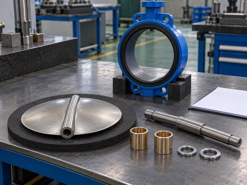
What information supports a bearing review?
Provide size, closed differential, temperature, fluid properties, duty, and drive arrangement. Identify normal disc positions. Uneven flow near fittings can add loads absent from a uniform approach flow.
- Record pressure direction and closed differential.
- Describe normal disc positions and cycling duty.
- Show nearby fittings and external drive weight.
Give the reviewer the operating duty. A valve used for occasional isolation faces a different movement history from one that continuously adjusts flow. Request approval for the intended duty instead of assuming the same bearing arrangement suits both.
What should maintenance monitor?
Record changes in operating effort, position repeatability, and shaft leakage under known conditions. Diagnose those symptoms against the installed model before attributing them to bearings. Key takeaway: orientation forms one part of a bearing assessment that also needs pressure, temperature, duty, and flow information.
| Input | Bearing review purpose |
|---|---|
| Closed differential | Pressure-related loading |
| Disc position | Dynamic flow loading |
| Drive arrangement | External mechanical loading |
Include the full operating duty in the valve enquiry.
5. How do solids affect butterfly valve stem orientation?
Butterfly valve stem orientation can influence exposure to settled solids where the model allows alternative positions. It cannot establish solids compatibility or guarantee that a disc will clear fibers and hard particles. Review the medium and seat construction before selecting a shaft axis.
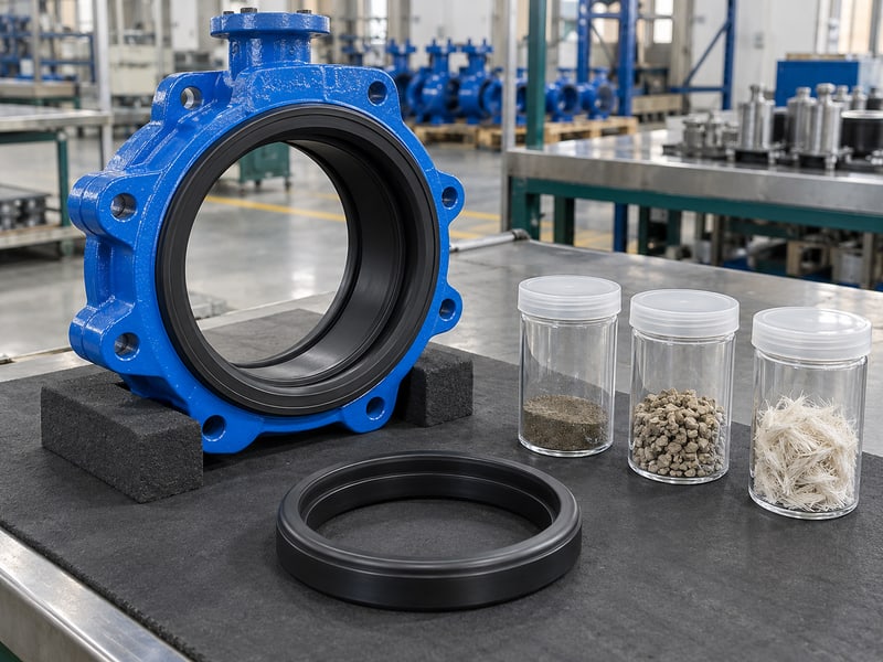
What should you tell the supplier?
Describe particle size, hardness, concentration, fiber content, and settlement during idle periods. RUITO's water and wastewater application information can help organize the enquiry, but each configuration needs a defined medium. Clarified water, low-abrasion treated water, and sludge require different reviews.
- Identify material that may collect around a shaft penetration.
- State flushing conditions and shutdown duration.
- Describe any risk of particles trapping at the seat.
Select for solids before selecting the shaft axis. Changing from vertical to horizontal may alter deposit locations without removing abrasive contact or disc obstruction. A proposed orientation should accompany an approved valve and process-cleaning arrangement.
What should an operating procedure prohibit?
Avoid additional drive force against suspected debris. Isolate, depressurize, and investigate through approved procedures. Key takeaway: an approved shaft position can support deposit control, while solids suitability remains a valve-selection decision.
| Solids characteristic | Review focus |
|---|---|
| Settling tendency | Deposit locations |
| Hard particles | Wear and seat damage |
| Long fibers | Disc obstruction |
Send a solids description and flushing plan with the drawing.
6. Do offsets change butterfly valve stem orientation?
Butterfly valve stem orientation for an offset design must follow its own section drawing and mounting instructions. Offset geometry changes the relationship among shaft, disc, bore, and sealing surface. It does not establish a universal permitted shaft position or pressure direction across all offset valves.
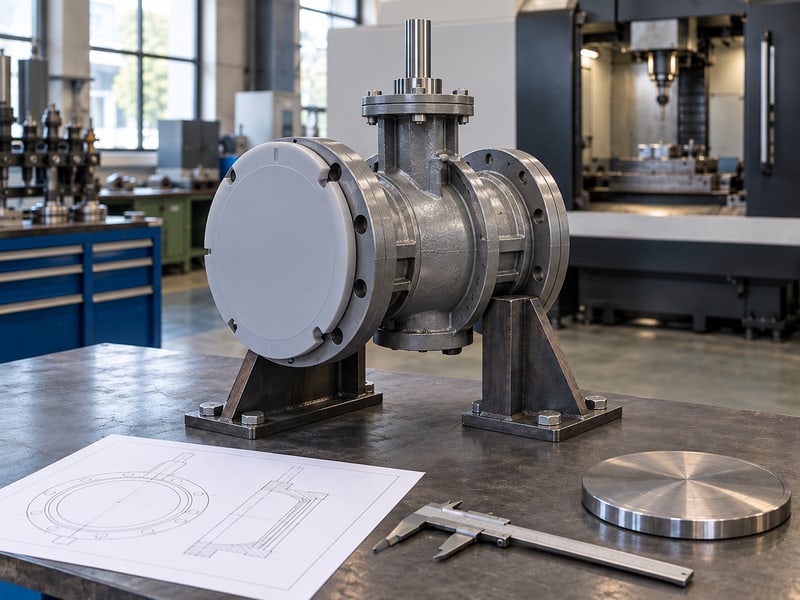
What differs between the constructions?
A concentric shaft lies near disc and pipe centerlines. Double offsets displace axes; triple offsets add inclined sealing geometry. Contact, torque, and working limits depend on the exact design.
- Confirm geometry from the model's section drawing.
- Check seat and shaft-retention construction.
- Obtain directional pressure and torque data.
Keep geometric offset separate from site rotation. Turning a body around the pipe axis does not change its internal offsets. Reversing body faces changes the pressure-side condition, which needs review against the directional shutoff ratings.
What matters in a replacement proposal?
Compare shaft location, operator mounting height, disc projection, and pressure-face instructions with the existing valve. RUITO's flanged butterfly valve options include separate concentric and double-eccentric configurations. Key takeaway: an offset replacement needs mechanical and directional review even when its flange interface matches.
| Geometry item | Compare |
|---|---|
| Shaft location | Drive and support position |
| Disc projection | Pipe clearance |
| Seat arrangement | Directional shutoff |
Request a section drawing before accepting the replacement layout.
7. What support suits butterfly valve stem orientation?
Butterfly valve stem orientation must retain an approved support path for the valve, pipe, and attached drive. Heavy equipment can load mounting flanges and brackets differently after reorientation. Pipe support should control external loads without forcing the body or shaft assembly out of alignment.
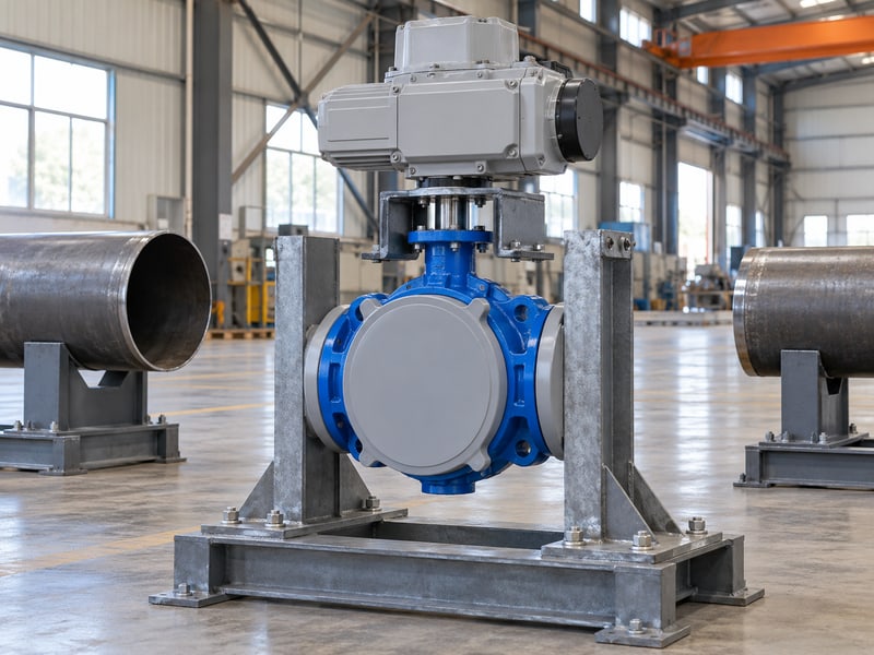
Where should external loads go?
Follow the drawing for operator support, lifting, and connection loads. A side-mounted drive can load its mounting connection in bending. Extensions and remote operators need an approved mounting arrangement.
- Show the drive weight and center of gravity.
- Identify valve and pipe support points.
- Include extensions, platforms, and moving control envelopes.
Support equipment through approved structural points. Do not improvise a support by clamping the exposed shaft or pushing against a service cover. Such a restraint can damage components or obstruct maintenance without carrying load as intended.
Can supports prevent thermal movement?
The piping design must account for thermal expansion and any forces transmitted to the valve. A rigid bracket added without review can restrain intended movement and increase connection loads. Key takeaway: review orientation and support together so operator weight and pipe movement use deliberate load paths.
| Load source | Required review |
|---|---|
| Operator weight | Mounting and support |
| Pipe movement | Connection loads |
| Extension assembly | Bending and alignment |
Submit the support detail alongside the shaft elevation.
8. Do shaft seals limit butterfly valve stem orientation?
Butterfly valve stem orientation must respect shaft-seal service instructions and access requirements. The seal construction, medium, temperature, and pressure determine its working limits. Rotating the body does not correct an incompatible seal or justify an unapproved packing adjustment.
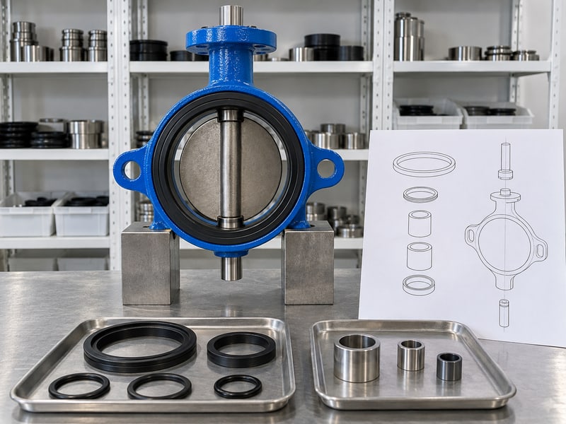
What does the seal review include?
Identify every wetted seal and lining around the shaft penetrations, including backing materials where relevant. A familiar material name does not cover all chemicals or temperatures. EPDM water-service seals should not be treated as a universal choice for oil or steam.
- Confirm actual fluid composition and cleaning agents.
- Review pressure and temperature together.
- Keep permitted inspection and service points accessible.
Review the complete wetted sealing arrangement. For RUITO's PTFE lined butterfly valve options, lining, backing, and shaft seals need coordinated assessment. Polymer lining on one component does not establish isolation of every wetted surface.
How should leakage be investigated?
Record leakage location and operating conditions, then isolate safely. Follow model instructions; excess tightening can raise friction or damage seals. Key takeaway: keep seals accessible and select materials for the actual medium.
| Seal question | Evidence needed |
|---|---|
| Compatibility | Complete medium description |
| Working limit | Model pressure-temperature data |
| Service access | Installed clearance |
Confirm access to the shaft-seal area on the final drawing.
9. How is butterfly valve stem orientation checked?
Butterfly valve stem orientation is checked by comparing the installed shaft axis, support, and movement with the approved arrangement. Verify the assembly before pressurization and through the project's commissioning procedure. An external position indicator alone cannot demonstrate correct shaft indexing or unobstructed disc travel.
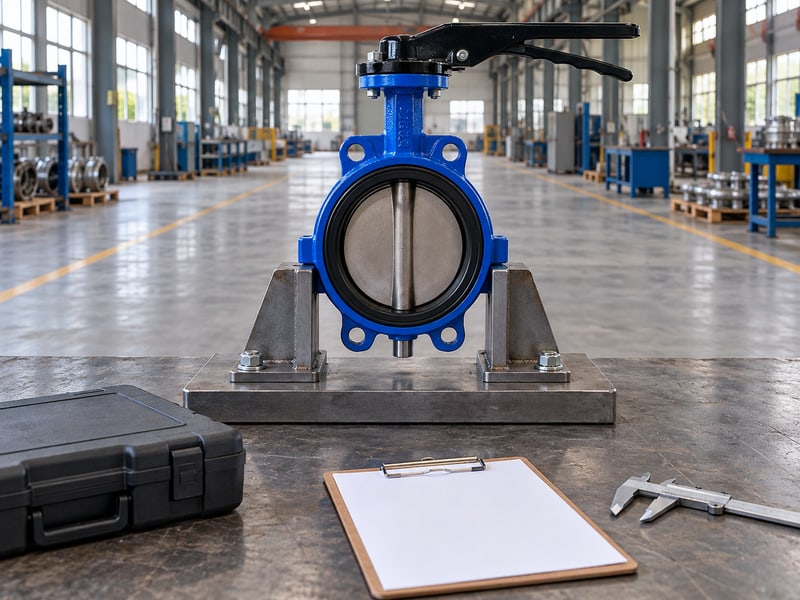
What should the mechanical check cover?
Confirm shaft position, pressure faces, supports, fasteners, and access. Keep people clear during approved movement checks. Record resistance, contact, or disagreement between indication and verified position.
- Compare installed position with the final drawing.
- Inspect supports and nearby movement obstructions.
- Verify the required travel and end-position indication.
Investigate resistance before increasing drive force. Binding can arise from flange interference, seat compression, a displaced support, or another assembly problem. Safely isolate and diagnose the cause instead of treating orientation as the only possible explanation.
What belongs in the commissioning record?
Record operating conditions, any required functional checks, and observations around the shaft seals. Keep approved changes attached to the valve tag and model documents. Key takeaway: inspection should establish that the installed shaft position works with the supplied assembly, supports, and disc envelope.
| Check stage | Record |
|---|---|
| Before filling | Position and free movement |
| Commissioning | Function and leakage observations |
| Handover | Final approved arrangement |
Close mechanical discrepancies before releasing the valve for operation.
10. Who approves butterfly valve stem orientation?
Butterfly valve stem orientation is approved through the model supplier's mounting limits and the project's engineering review. Procurement should retain that approval with the supplied configuration. A verbal agreement about access leaves bearing, seal, and support conditions difficult to verify during installation.
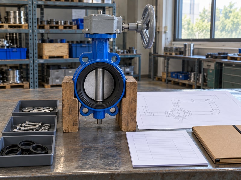
What information makes the enquiry useful?
Provide pipe and shaft axes, valve size, fluid composition, pressure in both directions, temperature, duty, and drive details. Add a plan and elevation with obstructions and supports marked. Send the proposed assembly position. The reviewer needs to see the complete arrangement to identify missing access or load information.
- Specify solids and idle-period conditions.
- Identify drive weight and support.
- State removal and inspection clearances.
What should the purchase specification require?
Ask for mounting limits, the approved assembly drawing, directional ratings, and installation instructions. RUITO can review the selected configuration against your inputs. Key takeaway: approve a reproducible shaft arrangement with defined service conditions; contact us today with your annotated layout.
| Enquiry item | Purpose |
|---|---|
| Shaft elevation | Define mounting position |
| Process conditions | Review bearings and seals |
| Support detail | Confirm external load path |
Include the approved position in the purchase and handover documents.
Frequently asked questions
Q1: Can I put every butterfly valve shaft horizontally?
No. Verify the exact valve, drive, bearings, and required supports against its mounting instructions.
Q2: What's the best shaft position for sediment?
Use a model-approved arrangement after reviewing settlement and solids. Orientation cannot make an unsuitable valve handle debris.
Q3: Can I install the actuator below the pipe?
Only if the complete assembly permits it. Review mounting, enclosure, drainage, support, and service access.
Q4: How do I know if offset geometry sets direction?
Check the directional seat and torque data. Offset count alone does not establish equal pressure ratings.
Q5: Can extra packing adjustment fix shaft leakage?
Only where the model permits adjustment. Isolate safely and follow its procedure before changing any setting.