
Fix butterfly valve manufacturing process mistakes by controlling materials, machining interfaces, seat fit, assembly, testing, and release against one approved configuration. A valve can look correct while a mismatched seat or misaligned shaft makes it leak. Start with the configuration, follow each production stage, and connect every acceptance record to the finished valve.
For an equipment buyer, discovering a tight valve during skid assembly creates more than a replacement task. You may need new mounting parts, another pressure test, and revised delivery dates. The checks below follow the parts-to-release sequence for a concentric soft-seat valve. Offset and lined designs need their own drawings and additional controls.
1. What starts a butterfly valve manufacturing process?
An approved specification starts the butterfly valve manufacturing process by defining what the valve must contain and withstand. Freeze the connection, nominal size, material, seat construction, service conditions, and inspection route before production. A part number without a drawing revision leaves room for changes that your installation team may never see.
Which inputs should you settle before machining?
Check the duty before the parts list. A clean-water valve and a mineral-oil valve may share a body casting while requiring different elastomers. State operating temperature, pressure, maximum closing differential, fluid composition, and actuator supply conditions. Then identify the mating flange standard and disc-opening clearance.
For example, an OEM replacing a compact wafer valve should compare the original face-to-face dimension with the proposed assembly drawing before ordering a production batch. An approval record should also name who can accept substitutions. Key takeaway: A frozen configuration gives you a clear basis for accepting every later operation.
- Specify the fluid and its concentration or additives.
- Approve the drawing, bill of materials, and inspection plan.
| Control | Acceptance evidence |
|---|---|
| Design basis | Approved duty and configuration |
| Revision | Matching drawing and parts-list issue |
2. How are body castings prepared and checked?
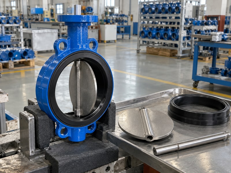
The body stage of the butterfly valve manufacturing process produces a sound blank with enough material for the specified machining allowance. For a cast body, the foundry controls the chosen metal and casting route, removes gates and risers, and cleans the surface. Inspection then checks identity, condition, and any contract-required material properties.
What should you ask about casting defects?
Inspect before coating hides the surface. Look for cracks, incomplete filling, shrinkage, and damaged sealing or support areas. The inspection plan should define the visual acceptance criteria and any additional examination. Chemical composition alone cannot establish every mechanical property of a ductile-iron casting.
Heat treatment, repair, and non-destructive examination depend on the actual material specification and contract. A casting supplier’s general certificate should not replace the records required for your production heat or batch. Keep rejected parts physically separated until their disposition is approved. Key takeaway: Identify casting problems while the surface remains accessible and the batch traceable.
- Link the casting batch with its material records.
- Approve any permitted repair through the agreed procedure.
| Control | Acceptance evidence |
|---|---|
| Material | Specified grade and applicable batch records |
| Condition | Accepted surface and repair disposition |
3. Which body dimensions control the finished fit?
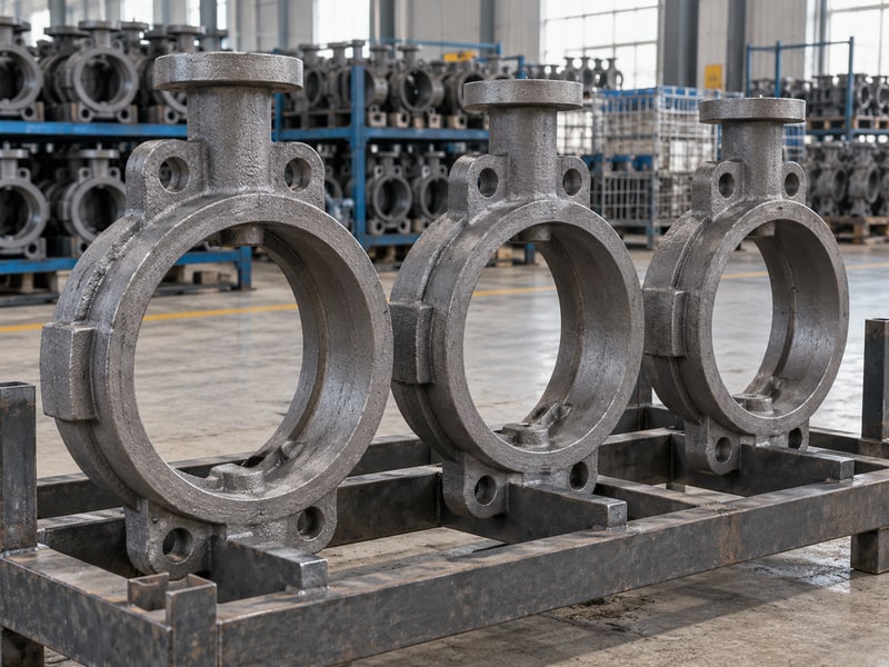
Body machining in the butterfly valve manufacturing process controls the seat pocket, shaft bores, connection faces, and operator interface. These features work together. An accurate bore diameter cannot compensate for an incorrectly located shaft axis or a face-to-face dimension that does not fit the intended pipe assembly.
How should you review the machining setup?
Follow the drawing datums. A controlled setup establishes where measurements begin and which surfaces locate the next operation. Check shaft-bore alignment, the seat-support surface, end-face geometry, and mounting dimensions against those references. Wafer and lug bodies need different connection checks.
A lug body adds thread form, depth, and usable engagement requirements. Any end-of-line duty requires a specific approved design and rating. Record the initial inspected component before continuing the batch, particularly after a fixture change, tool replacement, or drawing revision. Key takeaway: Control the relationship between machined features, not a collection of isolated dimensions.
- Check dimensions from the specified drawing datums.
- Verify mating flange clearance through the full disc travel.
| Control | Acceptance evidence |
|---|---|
| Seat pocket | Dimension and surface condition |
| Shaft bores | Position and alignment |
| Connection | Approved face-to-face and hole pattern |
4. How are the disc and shaft made compatible?
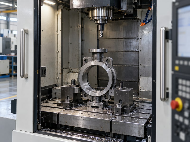
Disc and shaft production in the butterfly valve manufacturing process must create a matched rotating assembly. The disc edge provides the contact geometry for a resilient seat, while the shaft transmits torque and locates the disc. The shaft connection, retention arrangement, and bearing surfaces follow the selected design.
Where do small component errors become operating faults?
Pay attention to the sealing edge. Burrs, impact marks, an incorrect edge profile, or a damaged coating can harm a soft seat during assembly. Check the disc’s connection with the shaft and the specified means of preventing axial movement or loosening. Shaft seal-contact surfaces need the required finish and freedom from damage.
Do not assume that two shafts with the same exposed drive shape are interchangeable. Their shoulders, engagement length, seal locations, and retention features may differ. Use the approved component drawing for both machining and replacement orders. Key takeaway: Matched geometry helps the valve turn without damaging its seat or drive connection.
- Protect disc edges during handling and storage.
- Inspect drive fit, retention features, and shaft sealing surfaces.
| Control | Acceptance evidence |
|---|---|
| Disc | Edge profile and shaft interface |
| Shaft | Finish, engagement, and retention dimensions |
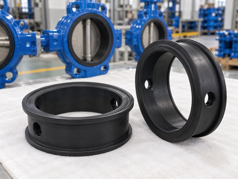
5. How does seat production affect sealing?
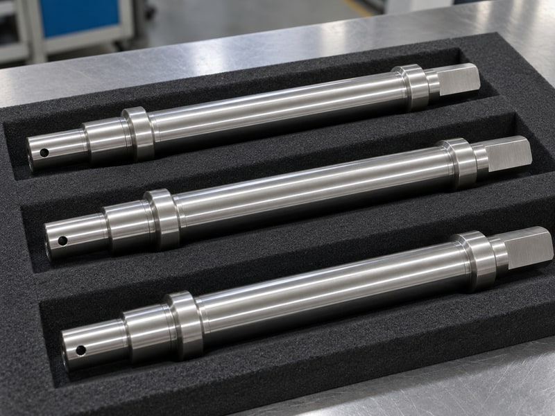
Seat production changes the butterfly valve manufacturing process because rubber, PTFE, and PFA follow different material and forming routes. An EPDM seat depends on its compound and cure. A conventional molded PTFE part uses an appropriate powder-processing route. The finished seat must also fit the body and disc geometry.
What belongs in a seat approval?
Specify the complete sealing construction. Name the compound or resin, backing, retention method, and contact conditions. Color does not identify a grade. Conventional PTFE processing differs from the melt-processing methods used for PFA; the resin manufacturer’s processing guidance helps distinguish those routes.
A chemical duty also needs review of exposed shafts, disc surfaces, and auxiliary seals. For lined products, a polymer seat alone does not establish continuous protection of every wetted surface. Inspect the specified thickness and continuity where the selected construction requires them. Key takeaway: Treat the seat as a controlled component within a complete sealing system.
- Maintain compound or resin batch identity.
- Check the seat profile, shaft openings, and flange sealing faces.
| Control | Acceptance evidence |
|---|---|
| Rubber seat | Approved compound and cure records |
| Lined construction | Specified coverage, thickness, and integrity |
6. What should happen before assembly begins?
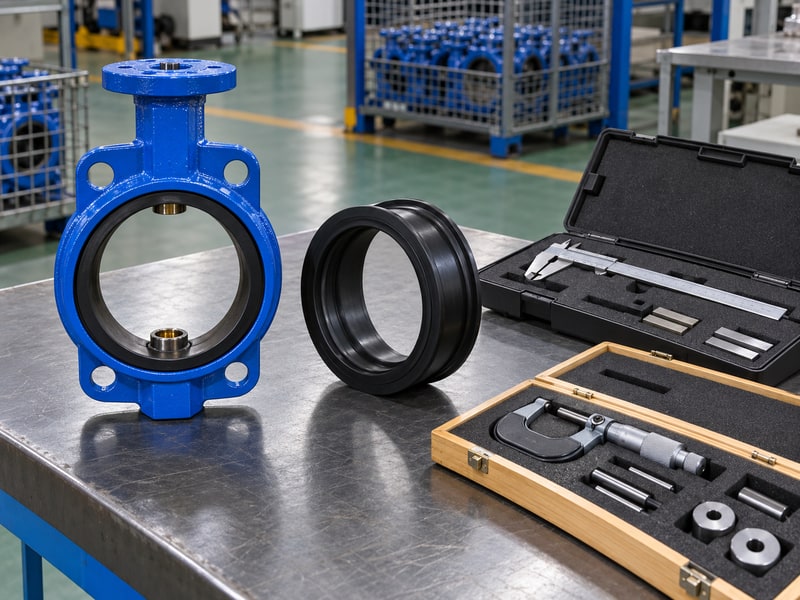
Pre-assembly preparation in the butterfly valve manufacturing process confirms that the parts are clean, accepted, and correct for the same configuration. Inspect the body, seat, disc, shaft, bearings, seals, and retaining components together. Separate similar-looking parts from other sizes, compounds, or drawing revisions before opening the assembly work order.
How do you prevent a wrong-part assembly?
Lay out one approved set. Use the parts list to check quantity and identity, then protect sealing surfaces from chips, grit, and coating residue. Assembly lubricant must suit the elastomer, fluid, and any hygiene requirements. Avoid applying a general-purpose oil to every rubber seat.
Confirm that measuring tools have current calibration status and suit the feature being checked. If an assembler finds damage or an uncertain material label, hold the set for review. A completed kit should retain its batch links even when individual labels are removed during installation. Key takeaway: A controlled kit prevents avoidable errors that a final pressure test may miss.
- Check cleanliness and component acceptance before fitting.
- Use only the specified assembly lubricant and replacement parts.
| Control | Acceptance evidence |
|---|---|
| Parts | Accepted identity and matching revision |
| Workstation | Clean surfaces and suitable equipment |
7. How are the seat, disc, and shaft assembled?
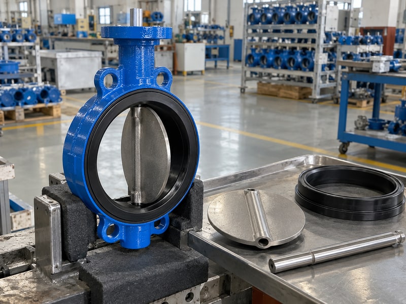
Assembly in the butterfly valve manufacturing process follows the model-specific sequence for installing the seat, disc, shaft, and retaining parts. Align the seat openings with the body shaft bores and protect the seat lip during fitting. Through-shaft and split-shaft designs require different handling and retention checks.
What should an assembler check during fitting?
Stop when resistance changes unexpectedly. Forcing a component can score the shaft, cut the seat, or move a bearing. Use the specified support tools and examine the cause before continuing. Check that the disc sits in its intended location and that retention parts fully engage.
A rubber sleeve may need a different insertion method from a hard-backed cartridge. Keep the seal construction visible in the work instruction rather than using one generic assembly sheet for every valve. Record any replacement component so the finished assembly remains traceable. Key takeaway: The correct sequence protects the matched sealing and rotating parts.
- Confirm shaft alignment and complete retention.
- Inspect the seat after fitting for cuts, twists, and displacement.
| Control | Acceptance evidence |
|---|---|
| Seat | Correct position and undamaged sealing lip |
| Disc and shaft | Specified alignment and secure retention |
8. How is the operator fitted and checked?
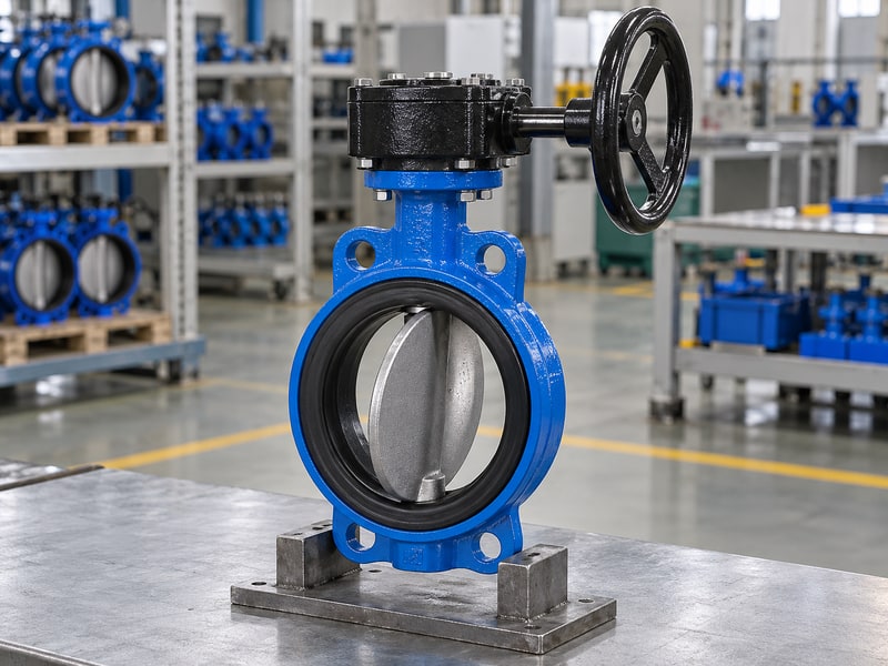
Operator fitting in the butterfly valve manufacturing process aligns the handle, gearbox, or actuator with the valve shaft and required travel. The selected drive must provide enough torque under the specified supply conditions while staying within permitted stem loads. Mounting-bolt alignment alone does not prove a correct drive connection.
Which operating checks should you request?
Verify the disc position directly. Confirm engagement depth, coupling fit, open and closed indexing, and the travel-stop settings. A motor reaching its limit does not establish that the disc has reached its approved sealing position. For pneumatic operation, compare the valve torque requirement with available output at the minimum stated air supply.
Include accessories and failure action when they form part of the order. Record functional travel and investigate excessive friction. Increasing actuator size to overcome an assembly fault can transfer damaging loads into the shaft and seat. Key takeaway: A correctly indexed operator makes its indication agree with the valve’s real position.
- Check drive engagement and actual disc travel.
- Use the accepted torque basis and minimum supply conditions.
| Control | Acceptance evidence |
|---|---|
| Mechanical fit | Engagement and mounting acceptance |
| Operation | Travel, torque, and accessory function |
9. Which tests verify the completed valve?
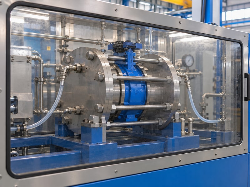
Final testing in the butterfly valve manufacturing process verifies the pressure boundary, closure performance, external sealing, and operation using the agreed procedures. Shell and seat tests serve different purposes. Test pressure, medium, duration, direction, and leakage acceptance must suit the actual configuration and selected standard.
How should you read a pressure-test report?
Read the conditions beside the result. RUITO’s stated room-temperature procedures include 15 bar shell and 11 bar soft-seat closure tests for applicable PN10 configurations, or 24 and 17.6 bar for applicable PN16 versions. These are inspection conditions, not operating-pressure upgrades. A directional seat rating can require a different reverse test.
Clean-air service needs its additional gas-tightness checks. Lined constructions add the specified lining examinations. Confirm the valve identity, calibrated instruments, hold duration, and leakage criterion instead of accepting a report that only says passed. Key takeaway: A useful result names both the valve and the conditions under which it passed.
- Separate shell, closure, external-leakage, and functional results.
- Link each report with the tested valve or accepted batch method.
| Control | Acceptance evidence |
|---|---|
| Shell test | Pressure boundary acceptance |
| Closure test | Specified direction and leakage criterion |
10. What closes the manufacturing and release record?
The butterfly valve manufacturing process ends when accepted hardware, identification, documentation, and packaging agree with the order. Review open deviations, inspection signatures, operator settings, and material links before dispatch. Protect the disc, shaft interfaces, flange faces, and exposed lining so shipping does not undo the completed inspection work.
What should arrive with the shipment?
Match the paperwork with the crate. The manufacturing record should let you move from the product identifier to its approved configuration and test results. Include the installation and maintenance instructions, relevant drawings, spare-parts information, and contract-required certificates. Large or actuated valves may need separate support for the body and operator.
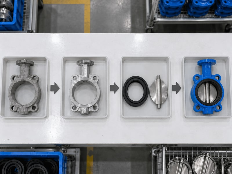
Packaging photographs can document those supports before the lid closes. A visual process sequence helps explain the route, but the signed records establish which operations your ordered valves completed. Close any agreed punch-list items before dispatch authorization. Key takeaway: Release a traceable, protected assembly with the documents your installation team will use.
- Check valve identity against the packing list and records.
- Protect sealing faces and support heavy operators during transport.
| Control | Acceptance evidence |
|---|---|
| Release file | Accepted inspections and closed deviations |
| Shipment | Matching identifiers and protective packaging |
Send RUITO your fluid, temperature, pressure, maximum closing differential, connection standard, and inspection requirements. We can review the configuration and proposed manufacturing records before you approve production. Contact us with the drawing or existing valve details so the quotation addresses the assembly you need.
FAQ
Q1: Can I use one inspection plan for every butterfly valve?
Use a common framework with configuration-specific checks. Seat construction, connection style, direction rating, operator, and service can change the acceptance requirements.
Q2: How do I know if a casting certificate covers my order?
Check its batch identification and required properties against the purchase specification. The manufacturing traceability record should connect that batch with the supplied body.
Q3: Can a larger actuator solve a tight valve?
Investigate the cause before changing the actuator. Misalignment, seat damage, wrong parts, or excessive preload can create binding and damaging shaft loads.
Q4: Does a passed shell test prove tight shutoff?
No. A shell test checks the pressure boundary. Closure leakage requires its own procedure, direction, medium, duration, and acceptance criterion.
Q5: What is the best document to request before shipment?
Request the agreed manufacturing record package with its index and product identifiers. It should include accepted test reports, relevant drawings, and closed deviations.