
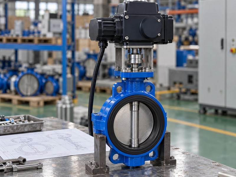
Fix butterfly valve motorized actuator mistakes by matching the output, mechanical connection, power supply, and control interfaces to the selected valve. A replacement that bolts down can still overload the stem or send misleading feedback. Review the assembled drawings and settings before ordering, then verify the supplied combination through its approved procedure.
1. What makes a butterfly valve motorized actuator compatible?
A compatible butterfly valve motorized actuator meets the valve's required torque, allowable input loads, travel, mounting, and control requirements together. Compatibility applies to the complete configured assembly, including any bracket, coupling, reduction gearbox, and electrical accessories.
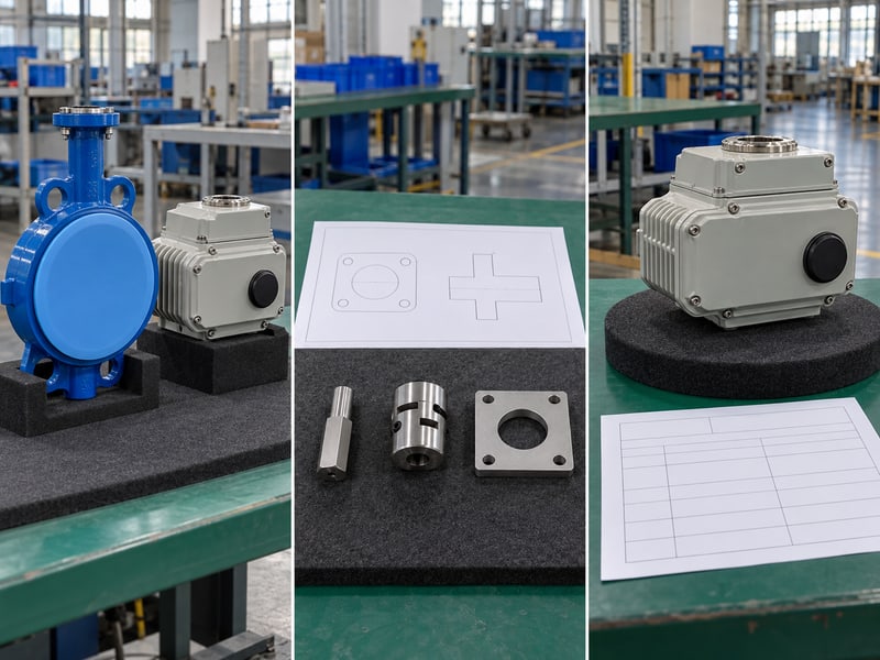
Which records identify the combination?
Match the documents to the supplied assembly. Start with the valve identification, actuator identification, and approved assembly drawing. Where a reducer or adapter sits between them, its dimensions and ratings belong in the same review rather than remaining an undocumented workshop choice.
- Identify the valve and actuator configurations.
- List intervening drive and mounting parts.
- Check drawing and instruction revisions.
A catalogue mounting size cannot confirm that a particular insert reaches the stem correctly or that the fitted controller supports the requested command. Record those features before accepting a replacement, especially when the original equipment documents describe only the valve body.
What should approval cover?
Key takeaway: Approve a defined combination of mechanical and electrical components. Keep their identification together so a later replacement can be compared against the accepted arrangement.
| Record | Confirms |
|---|---|
| Assembly drawing | Complete connection |
| Rating data | Operating limits |
| Control schedule | Commands and signals |
Ask the supplier to identify any outstanding interface checks. Close those items before releasing the assembly for manufacture or replacement.
2. What output must a butterfly valve motorized actuator deliver?
A butterfly valve motorized actuator must deliver the required torque throughout the specified valve travel while respecting the assembly's allowable input limits. Compare available output with breakaway, running, and seating requirements under the stated service conditions.
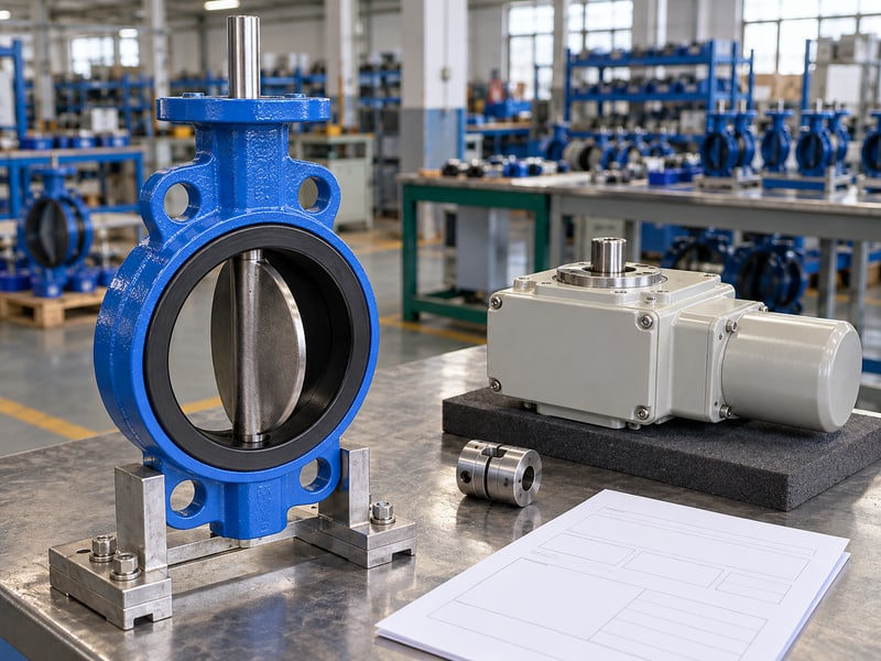
How should you read a sizing proposal?
Compare required and permitted torque on the same basis. Check what conditions support the quoted output and whether the value describes rated, limited, or maximum delivered torque. Motor power alone cannot establish the torque available at a valve stem after the complete drive train.
- Confirm maximum closing differential.
- Include fluid, temperature, and operating frequency.
- Check stem, coupling, and gearbox input limits.
A stronger actuator can exceed the load that a stem or drive insert may accept if its limiting arrangement is unsuitable. Request the selected output, permitted settings, and protection strategy together; an unexplained increase in torque setting is not an accepted cure for mechanical resistance.
Which values need an engineering record?
Key takeaway: Sizing needs both a required output and an allowable input. The review should show how the selected actuator completes travel without overstressing the assembled connection.
| Quantity | Review basis |
|---|---|
| Required torque | Selected valve duty |
| Available output | Stated actuator conditions |
| Permitted input | Weakest rated drive component |
Request the torque review for the actual configuration. Resolve missing conditions before comparing competing actuator quotations.
3. What drive fit suits a butterfly valve motorized actuator?
The drive connection of a butterfly valve motorized actuator must match stem geometry, engagement length, axial clearance, and retention requirements. A mounting flange that seats correctly does not reveal every dimension inside the coupling.
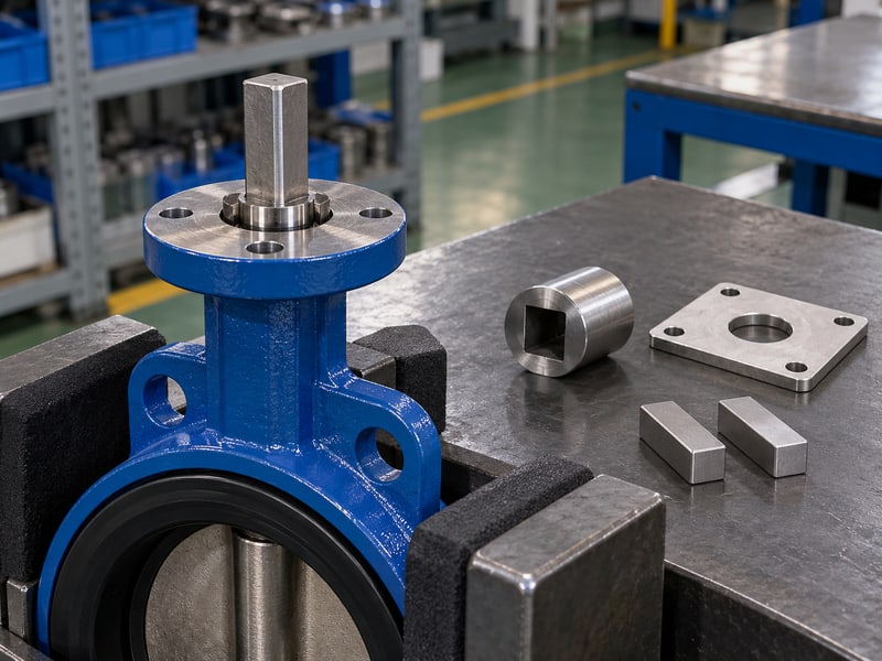
Which dimensions control the connection?
Check engagement before tightening the mount. Compare the actual square, key, or spline arrangement with the approved detail, including insert depth and stem projection. An insert can grip too little stem or bottom out before the mounting faces meet.
- Confirm drive profile and tolerances.
- Verify specified engagement length.
- Check axial clearance and retention.
An ISO 5211 mounting interface, where specified, does not independently guarantee torque capacity or compatibility. For a wafer butterfly valve, review the drive detail alongside the body and disc-clearance drawing; the short pipewise body length says nothing about insert engagement.
What should the inspection establish?
Key takeaway: Accept the drive fit against its approved dimensions. Avoid using mounting bolts to pull together parts that resist seating because their drive stack is incorrect.
| Feature | Acceptance basis |
|---|---|
| Drive shape | Approved mating detail |
| Engagement | Specified contact length |
| Axial fit | Clearance and retention drawing |
Record the checked dimensions before covering the coupling. Refer an unexplained fit problem to the supplier before applying operating energy.
4. What mounts carry a butterfly valve motorized actuator?
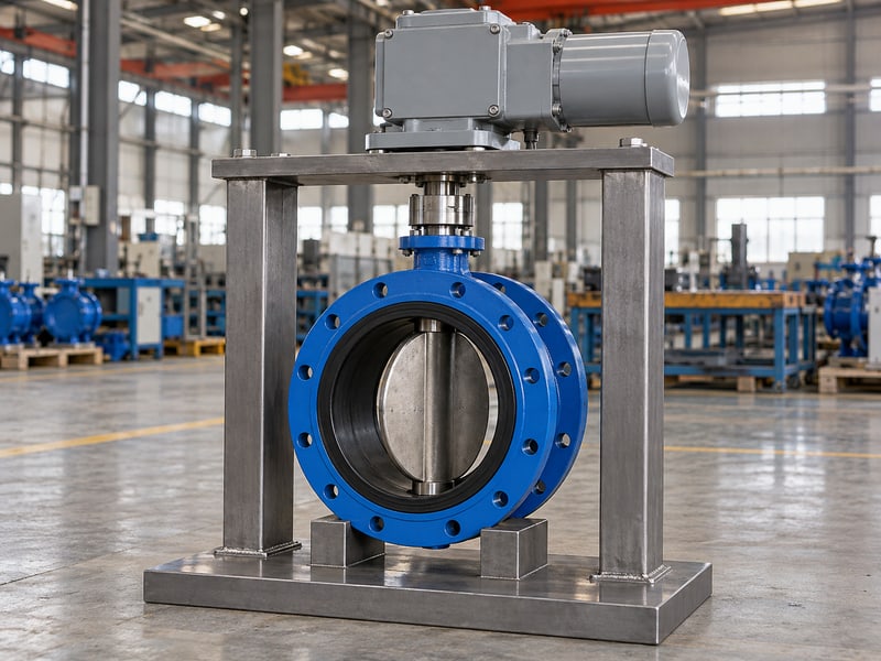
The approved mounting assembly carries the weight and operating reactions of a butterfly valve motorized actuator while maintaining stem alignment. Its bracket, fasteners, valve mounting neck, and any specified support must work as one load path.
Which loads need separate review?
Check the bracket for load as well as hole spacing. Actuator mass and centre of gravity can bend an overhanging mount, while operating torque loads its fasteners and housing connection. A larger replacement may change those loads even when the bolt pattern remains the same.
- Confirm mounting mass and overhang.
- Check fastener specification and engagement.
- Review support and pipe movement allowances.
For flanged butterfly valve assemblies, pipeline flange strength cannot establish the capacity of the actuator bracket or neck. Use the approved support arrangement, and keep cable conduit from carrying housing weight or restraining movement that the mechanical design permits.
What belongs on the mounting drawing?
Key takeaway: The mount must preserve alignment under its assigned loads. A dimensional match needs a load review before a heavier or differently configured actuator is accepted.
| Load | Review point |
|---|---|
| Housing weight | Bracket and overhang |
| Operating reaction | Mount and fasteners |
| Pipe movement | Approved restraint |
Request any required support details with the assembly drawing. Inspect the installed load path before the functional check.
5. What travel fits a butterfly valve motorized actuator?
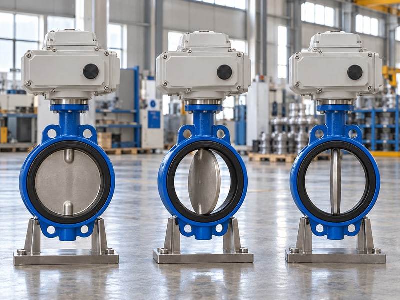
A butterfly valve motorized actuator needs output travel and stopping behaviour coordinated with the selected valve's approved endpoints. Its mechanical stops, limit functions, and torque protection must support that seating arrangement without forcing extra disc movement.
How should endpoints be coordinated?
Use the valve's approved seating method. Some assemblies use particular position or torque criteria at an endpoint, so the actuator instructions alone may leave part of the setting decision unresolved. Ask which component defines open travel and which accepted condition defines closure.
- Identify each travel-limiting component.
- Confirm approved endpoint criteria.
- Record allowed adjustments and locking methods.
Where a multi-turn actuator drives a separate quarter-turn gearbox, the intermediate ratio and input travel also need confirmation. Do not transfer settings from a direct-drive unit merely because both operate the same nominal valve size; their drive paths can differ.
What should a settings sheet show?
Key takeaway: Coordinate all stopping functions against the actual valve travel. A closed indication cannot justify moving beyond an approved seating position.
| Function | Defined by |
|---|---|
| Open endpoint | Approved travel reference |
| Closed endpoint | Valve seating procedure |
| Protective limit | Assembly load requirements |
Request a settings sheet for the complete drive train. Verify the accepted endpoints after any approved coupling or operator replacement.
6. What supply fits a butterfly valve motorized actuator?
The electrical supply for a butterfly valve motorized actuator must match the configured power input, control supply, and connection requirements. Review voltage, frequency where applicable, phase arrangement, and available supply conditions against the actual actuator data.
What should electrical engineering compare?
Distinguish motor power from control power. An assembly may have separate requirements for its motor, controller, heater, or accessories. A familiar control voltage on one terminal does not establish that the main supply or every output contact uses that voltage.
- Confirm each required supply circuit.
- Check connection and protection requirements.
- Review ambient and cycling conditions.
The electrical team should size cables and protection using the supplied data and project rules. Operating frequency, stroke duration, ambient temperature, and available voltage belong in the actuator review; avoid assigning a generic duty percentage to every electric drive.
Which supply details must be explicit?
Key takeaway: State power and control supplies separately where the assembly requires them. The supplier's configured electrical documents must agree with the site's available circuits.
| Circuit | Required information |
|---|---|
| Motor input | Configured electrical rating |
| Controls | Supply and signal interface |
| Accessories | Separate loads, where fitted |
Send the site supply schedule with the enquiry. Have electrical engineering close discrepancies before termination or energisation.
7. What commands suit a butterfly valve motorized actuator?
Commands for a butterfly valve motorized actuator must match its configured controller and the intended operating sequence. Define on/off, positioning, local, remote, and failure-response requirements before assigning control-system outputs.
What should the command schedule state?
Map each command to an agreed response. Identify the interface type, permitted command combinations, local-control priority, and any project interlocks. Different actuator controllers can require different signal arrangements even when their main power ratings match.
- Define open, close, and stop functions.
- Record local and remote selection behaviour.
- State responses to supply and signal loss.
For HVAC and district energy systems, a positioning command also needs an approved process response and operating duty. A control signal that requests an angle does not independently establish flow accuracy, acceptable throttling, or suitability for frequent repositioning.
How should failure behaviour be documented?
Key takeaway: Confirm loss of command and loss of power separately. Any required final position, reserve-energy arrangement, and restart behaviour needs an explicit assembly specification.
| Condition | Defined response |
|---|---|
| Remote command | Agreed movement or hold |
| Local selection | Agreed control priority |
| Energy or signal loss | Approved final-state behaviour |
Review the response schedule with controls engineering. Ask the supplier to identify any requested behaviour the quoted configuration cannot provide.
8. What feedback proves a butterfly valve motorized actuator works?
Verified position and status signals show whether a butterfly valve motorized actuator responds as intended, but each signal needs a defined meaning. An accepted close command, a stopped motor, and a confirmed closed valve are different observations.

Which feedback signals should you distinguish?
Define what each contact or value represents. Separate commanded position from measured actuator position, and distinguish endpoint indication from fault or availability status. Confirm whether feedback remains valid during local operation, loss of power, or a disconnected drive connection.
- Identify open and closed indications.
- Define intermediate position, where supplied.
- Record fault and availability conditions.
In a hypothetical replacement, the controller could report an actuator output position correctly while an incorrectly indexed coupling places the disc elsewhere. Comparing feedback with the approved valve reference during assembly verification can reveal that mismatch before remote operation begins.
What makes feedback acceptable?
Key takeaway: Signal mapping must agree with verified valve travel and documented status meanings. A changing display value alone cannot prove that the assembled valve moves correctly.
| Signal | Verification |
|---|---|
| Endpoint | Approved actual travel |
| Position value | Agreed scale and reference |
| Status contact | Documented operating condition |
Record the accepted mapping at the control-system interface. Resolve ambiguous or contradictory indications before operational handover.
9. What documents guide a butterfly valve motorized actuator?
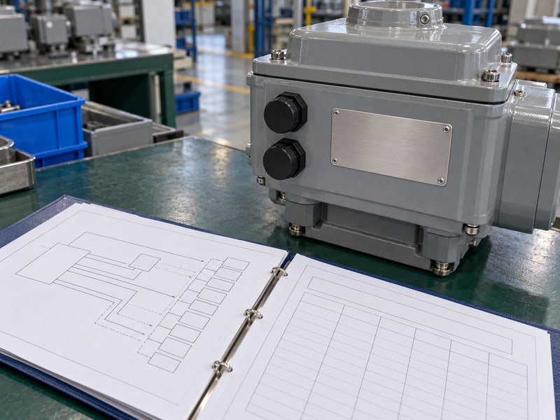
The configured wiring diagram, terminal schedule, settings record, and assembly instructions guide a butterfly valve motorized actuator installation. Those documents must identify the supplied controller and accessories, rather than describing an unspecified option from the same catalogue.
Which details should the terminal schedule include?
Check terminal functions against the fitted configuration. Electrical engineering needs conductor identification, circuit function, interface requirements, and applicable connection details. A terminal number copied from an older unit can have a different purpose on a replacement controller.
- Identify power and protective connections.
- List command, feedback, and accessory circuits.
- Match document revision to supplied equipment.
Confirm unused-entry closure, cable termination, and enclosure requirements through the specific instructions. Qualified personnel should perform electrical work under the site's isolation procedure; generic diagrams cannot establish conductor destinations or safe energisation for every actuator model.
What should remain in the handover file?
Key takeaway: Retain the configured documents and accepted settings with the assembly identification. Record approved changes so the next technician can trace the installed circuit functions.
| Document | Purpose |
|---|---|
| Wiring diagram | Circuit connections |
| Terminal schedule | Interface identification |
| Settings record | Accepted operating configuration |
Return discrepancies for correction before connection. Keep the final accepted revision with the valve's maintenance records.
10. How is a butterfly valve motorized actuator verified?
Verify a butterfly valve motorized actuator as an assembled unit through the approved inspection and functional procedure, then repeat the relevant installed-interface checks. The agreed scope should connect mechanical travel, protective settings, commands, and feedback to the supplied assembly identification.

What evidence should the supplier provide?
Agree the acceptance scope before release. Request the mounting inspection, drive-fit record, settings sheet, and functional results specified by the order. Identify the test conditions so an unpressurised travel check is understood separately from any agreed load or valve leakage verification.
- Compare the supplied configuration with approved records.
- Verify endpoints and command responses.
- Check feedback and agreed failure behaviour.
A valve pressure-test report cannot prove controller mapping or endpoint agreement. Equally, a successful electrical movement check cannot establish the valve's approved pressure-temperature or directional closing limits, which remain tied to its selected construction.
What should the release checklist require?
Key takeaway: Acceptance evidence should cover the assembled interfaces named in the order. Close missing records and unresolved discrepancies before shipping or operational handover.
| Interface | Acceptance evidence |
|---|---|
| Mechanical | Fit and mounting checks |
| Operating | Accepted travel and settings |
| Electrical | Agreed commands and feedback |
Send RUITO the valve duty, interface drawings, supply schedule, and control requirements; contact us today to review the proposed assembly. Request confirmation of the configured documents and verification scope before purchase.
Frequently asked questions
Q1: Can I replace an actuator with one that has the same bolt pattern?
Only after a complete compatibility check. Confirm torque limits, drive engagement, travel, mounting loads, power, controls, and the supplied documentation.
Q2: What's the best way to compare output torque ratings?
Use a common set of operating conditions. Compare the valve's required torque with available actuator output and the allowable input of every intervening drive component.
Q3: How do I know whether the closed signal is accurate?
Verify it against the approved actual valve position. Check coupling indexing, endpoint settings, and the documented meaning of the feedback signal together.
Q4: Can I reuse the wiring diagram from the old actuator?
Only if the supplier confirms it matches the replacement configuration. Otherwise use its configured wiring diagram and terminal schedule before connecting any circuit.
Q5: Will an electric actuator always close when power fails?
No. The final state depends on the selected mechanism, reserve energy, and control arrangement; specify and verify the required response for the complete assembly.