
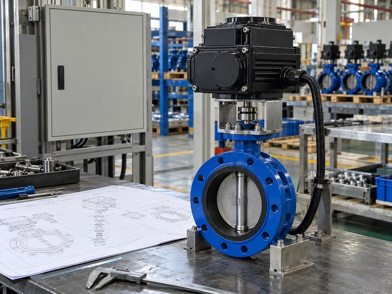
Fix motorized butterfly valve wiring diagram errors by matching the drawing to the fitted actuator, then checking power, command, and feedback circuits separately. A familiar terminal label can have a different function on a replacement unit. Use the configured documents and a staged verification record before releasing the valve for remote operation.
1. Which motorized butterfly valve wiring diagram applies?
The motorized butterfly valve wiring diagram issued for the actual actuator, controller, and fitted options applies. Confirm its document number and revision against the supplied equipment, including accessories added after the original valve assembly was specified.
What identifies the correct drawing?
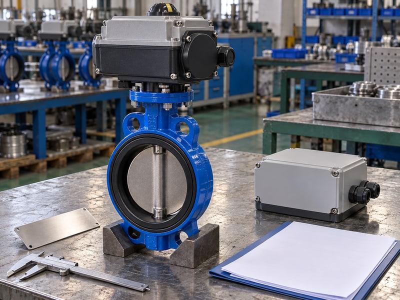
Match the hardware before interpreting the terminals. Record the actuator identification and configured control option, then compare them with the drawing's applicability notes. A diagram for another voltage, controller, or accessory package can look similar while assigning different functions to the same terminal positions.
- Check equipment and drawing identification.
- Confirm the fitted electrical options.
- Resolve document revisions and approved changes.
The valve tag identifies a process location, but it may not describe the controller inside the actuator. Keep the tag-to-equipment relationship with the wiring records so maintenance can identify the installed hardware without relying on an old procurement description.
What should the installer receive?
Key takeaway: Use a configured drawing with traceable equipment identification. A catalogue example or old drawing needs a confirmed applicability check before connection work begins.
| Identification | Compare with |
|---|---|
| Actuator | Supplied equipment label |
| Controller option | Configuration record |
| Drawing revision | Accepted document list |
Ask the supplier to close any mismatch in writing. Retain the accepted diagram at the installation and maintenance handover points.
2. What power does a motorized butterfly valve wiring diagram show?
A motorized butterfly valve wiring diagram identifies the power circuits required by the configured actuator and its accessories. It should distinguish motor supply, controller supply, and any separately supplied loads rather than treating every conductor as a command signal.
Which supply details need checking?
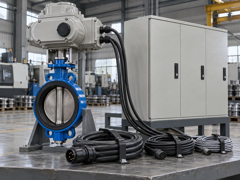
Compare each power circuit with the site supply schedule. Check the specified electrical characteristics and connection requirements for that circuit, including frequency or phase where applicable. The presence of a familiar control voltage does not identify the motor supply or establish an accessory's rating.
- Confirm each required power source.
- Identify separately supplied accessories.
- Check cable and protective-device requirements.
Electrical engineering should select cables and protection using the configured equipment data and project rules. Avoid borrowing a conductor size or protective-device rating from another actuator; the relevant loads, installation route, environmental conditions, and available supply may differ.
What should the power schedule record?
Key takeaway: Identify every supply and its isolation boundary before termination. Separate circuit records help prevent an accessory feed from being overlooked during maintenance.
| Circuit | Record |
|---|---|
| Motor | Specified supply characteristics |
| Controller | Required supply arrangement |
| Accessories | Feed and isolation details |
Return missing ratings to the supplier for clarification. Have electrical engineering approve the circuit schedule before connecting the equipment.
3. What commands does a motorized butterfly valve wiring diagram show?
A motorized butterfly valve wiring diagram shows how the fitted controller receives its agreed commands. The project control schedule must define what each command means, including movement, hold behaviour, local selection, and any interlocks.
How should you describe command functions?
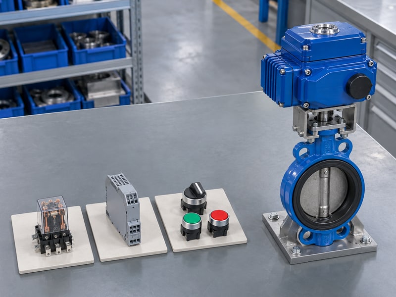
Write the expected response beside each input. Identify whether a command uses contact switching, a powered digital signal, an analogue interface, or another configured method. Conductor count alone cannot establish which method the actuator accepts or how conflicting commands are handled.
- Define open, close, and stop requirements.
- Confirm local and remote control priority.
- Identify any positioning or permissive inputs.
In HVAC and district energy systems, an analogue position request needs an agreed signal range and action direction. The electrical command represents a requested position; actual flow response still depends on the selected valve and system operating conditions.
What should the command record contain?
Key takeaway: Pair each input circuit with its approved response. Keep electrical signal type and process function together so controls staff can compare the diagram with the control program.
| Input detail | Defined requirement |
|---|---|
| Signal type | Compatible electrical interface |
| Command meaning | Accepted movement or hold |
| Priority | Local and remote sequence |
Review the mapping with the actuator supplier and controls engineer. Resolve unclear command combinations before commissioning software or wiring changes.
4. How does a motorized butterfly valve wiring diagram match inputs?
A motorized butterfly valve wiring diagram must match the electrical behaviour of the actuator inputs with the connected controller outputs. Review source, sink, dry-contact, and analogue arrangements using the documents for both ends of the circuit.

Why do interface descriptions need detail?
Check the current path and reference arrangement. A sourcing digital output supplies current to a compatible receiving circuit, while a sinking output provides its return path. Confirm the relevant common connections, operating limits, and isolation provisions from the actual equipment drawings.
- Identify output and input circuit types.
- Confirm reference and supply ownership.
- Check interface limits and configuration settings.
A dry contact describes a switching contact that does not itself supply the signal voltage. Its receiving circuit still needs the approved sensing arrangement, and the contact must meet the stated electrical requirements; avoid assuming that any relay can replace any transistor output.
What should the compatibility table show?
Key takeaway: Match both ends of every interface before applying a signal. For analogue circuits, confirm the required active or passive arrangement and signal reference through the configured documents.
| Interface | Compatibility check |
|---|---|
| Digital | Source or sink relationship |
| Contact | Sensing supply and contact rating |
| Analogue | Signal and reference arrangement |
Have controls engineering approve the interface matrix. Use an approved interface device where the supplied circuits cannot connect directly.
5. What feedback does a motorized butterfly valve wiring diagram show?
The motorized butterfly valve wiring diagram identifies feedback and status circuits fitted to the actuator. Define whether each circuit reports an endpoint, output position, availability, selection state, or fault before assigning its control-system meaning.
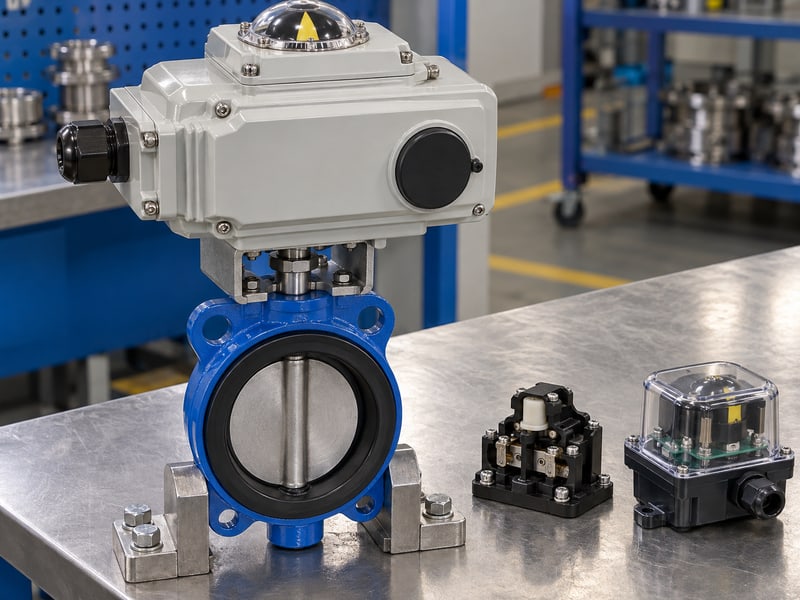
Which feedback functions must remain distinct?
Separate position indications from command status. A close command confirms a request, while an endpoint signal reports its configured detection condition. Neither should be labelled confirmed isolation unless the project defines and verifies what that term requires from the assembled valve.
- Identify open and closed indications.
- Define position scaling, where supplied.
- Record fault and availability meanings.
Check contact arrangements and analogue output requirements against the receiving input data. In a hypothetical replacement, a controller may accept the new actuator's signal electrically while interpreting a changed contact state incorrectly; the display could then show available when the actuator is unavailable.
What makes the feedback mapping acceptable?
Key takeaway: Feedback needs a documented electrical interface and verified meaning. Compare the accepted signals with actual valve travel and the configured actuator status during functional checks.
| Feedback | Record |
|---|---|
| Endpoint | Detection and valve reference |
| Position | Range and action direction |
| Status | Meaning of each state |
Include both electrical and functional checks in the test sheet. Close contradictory indications before enabling unattended remote operation.
6. How does a motorized butterfly valve wiring diagram protect cables?
A motorized butterfly valve wiring diagram, together with its installation instructions, defines connection details that support cable protection and enclosure integrity. The project layout must also address routing, earthing, shielding where required, and the actual external environment.
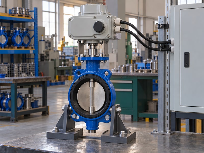
Which installation details need coordination?
Check cable entry and circuit separation together. Select glands, plugs, cable supports, and termination methods for the approved enclosure and cable arrangement. Follow the equipment instructions and project electrical design for power-signal separation and screen connections rather than applying one bonding rule everywhere. Where the enclosure declares an IP code, IEC 60529 defines the protection classification; confirm the fitted entries preserve the specified arrangement.
- Confirm protective connections where specified.
- Keep entries and unused openings correctly sealed.
- Review cable support and service access.
A signal common and a protective-earth connection perform different functions. For chemical processing installations, review external splash, cleaning chemicals, and cable-jacket exposure separately from the valve's wetted-material suitability; a compatible process lining cannot establish external electrical protection.
What should the installation check record?
Key takeaway: Connection protection depends on the finished cable and enclosure arrangement. Use the approved earthing and screening details for the actual equipment and site.
| Feature | Check |
|---|---|
| Cable entry | Approved gland and seal |
| Protective connection | Equipment and project requirements |
| Routing | Support and circuit separation |
Inspect the entries after termination and cover closure. Record any environmental condition the quoted enclosure or cable arrangement does not cover.
7. How is a motorized butterfly valve wiring diagram checked safely?
Check a motorized butterfly valve wiring diagram against the installed circuits under the approved electrical and process isolation procedure. Identify every energy source before opening equipment or changing conductors, including separately supplied accessories and any stored-energy arrangement.

What should the isolated inspection compare?
Trace identification before testing circuit continuity. Qualified personnel should compare terminal functions, conductor labels, cable schedules, and approved changes with the configured drawing. Verify isolation through the site's procedure rather than treating an actuator's local selector or remote stop command as electrical disconnection.
- Confirm the isolation boundaries.
- Compare installed conductor identification.
- Inspect terminations and protective connections.
Plan any continuity or insulation testing with the equipment instructions so sensitive electronics are treated as required. Process isolation and movement control also need review where a command or stored energy could move the disc and affect neighbouring equipment.
What evidence should precede energisation?
Key takeaway: Accept circuit identification and the required isolated checks before powered testing. Record discrepancies so the energisation decision rests on inspected installation details.
| Check | Evidence |
|---|---|
| Isolation | Approved procedure completion |
| Identification | Circuit-to-drawing comparison |
| Inspection | Accepted termination findings |
Correct discrepancies under controlled isolation. Use the authorised energisation procedure only after the responsible electrical and operating teams accept the work.
8. How is a motorized butterfly valve wiring diagram verified?
Verify a motorized butterfly valve wiring diagram through staged functional checks that compare each circuit's intended action with observed actuator and valve behaviour. The approved procedure should separate local checks, remote commands, feedback mapping, and any agreed interlock tests.

Why should testing proceed in stages?
Prove one defined function before combining sequences. Begin at the stage specified by the project and equipment instructions, with the area and process conditions controlled. Testing several new commands together can make a wrong input mapping difficult to distinguish from an interlock or feedback problem.
- Check the agreed local functions.
- Verify individual remote command responses.
- Compare feedback with accepted valve references.
Keep expected and observed results together on the test sheet, including selector state and relevant supply conditions. A successful local movement cannot confirm that the remote controller uses the correct command terminals, and a changing display cannot establish acceptable disc endpoints.
What should a stage record contain?
Key takeaway: Record the tested function, conditions, expected response, and observed result. Hold later stages when a discrepancy prevents the team from interpreting the next test reliably.
| Record item | Purpose |
|---|---|
| Test condition | Repeatable setup |
| Expected response | Acceptance criterion |
| Observed result | Traceable finding |
Investigate a failed stage before extending the sequence. Repeat affected checks after an approved correction and retain the final results with the equipment record.
9. What losses must a motorized butterfly valve wiring diagram cover?
A motorized butterfly valve wiring diagram and control-response schedule must address loss of motor supply, control supply, and command signal as applicable. These conditions can leave different circuits active and produce different valve or feedback states.
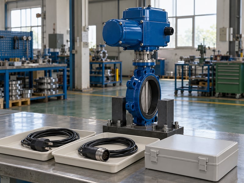
Which failure conditions should be specified?
Define each loss event and its recovery separately. Identify the required final state and the means by which the selected actuator can reach or retain it. A reserve-energy option, signal-loss setting, and controller restart sequence each need confirmation for the fitted configuration.
- Define supply-loss response.
- Define command-signal-loss response.
- Record recovery and restart behaviour.
For water and wastewater systems, the operating team must also review how an unexpected movement affects the process sequence. A generic fail-close description cannot establish the right final position, movement time, feedback validity, or restart action for every valve location.
What should the response matrix show?
Key takeaway: Confirm failure behaviour by event rather than by a single label. Specify what happens to movement and indication during loss, then state what happens when the lost source returns.
| Event | Required record |
|---|---|
| Power loss | Movement and retained state |
| Signal loss | Configured command response |
| Recovery | Restart and indication behaviour |
Agree the matrix before conducting controlled failure checks. Record the results under the project's accepted verification conditions.
10. What motorized butterfly valve wiring diagram records are needed?
Keep the final motorized butterfly valve wiring diagram, terminal schedule, interface mapping, approved settings, and verification results with the installed equipment identification. Those records show what was connected and accepted, including changes made during commissioning.

What should the final document set contain?
Close the drawing changes before handover. Reconcile approved field changes with the final supplier and project drawings. Include cable and conductor identification, controller input/output mapping, configured response settings, and the staged results that support release of the installed circuits.
- Match records to equipment and process tags.
- Retain accepted drawing revisions.
- Identify unresolved items and responsible owners.
Photographs can support a termination record, but they cannot replace a readable terminal schedule or a documented circuit function. Provide maintenance with the electrical isolation references and the applicable equipment instructions so later work begins from the accepted installed arrangement.
What should the release record confirm?
Key takeaway: Handover needs a consistent document set and traceable findings. Close circuit and response discrepancies before approving the valve for its intended automatic operation.
| Evidence | Confirms |
|---|---|
| Final drawings | Installed circuit arrangement |
| Interface schedule | Signal type and meaning |
| Verification record | Accepted operating responses |
Send RUITO the actuator identification, site supply data, and controller interface requirements; contact us today to review the configured electrical documents. Request the terminal schedule and agreed verification scope with the proposed valve assembly.
Frequently asked questions
Q1: Can I wire a replacement by copying the old terminal numbers?
Use them only after applicability is confirmed. Match the fitted actuator and controller to the accepted drawing revision before using any previous connection record.
Q2: What's the best way to match a PLC output to an actuator input?
Compare both circuit specifications. Check signal type, source or sink arrangement, sensing supply, reference connections, and interface limits with controls engineering.
Q3: Does a dry contact mean that no voltage is involved?
No. The contact does not supply voltage itself, but the receiving circuit may apply a sensing supply through the approved arrangement.
Q4: How do I know whether closed feedback proves the valve is shut?
Verify its defined detection condition against actual valve travel. A command or actuator signal alone cannot establish the approved seating condition or leakage performance.
Q5: Will losing the signal produce the same result as losing power?
The results match only when the configured response specifies it. Review and verify each loss event, feedback state, and recovery sequence separately.