
Fix mechanism mistakes by tracing how a butterfly valve works from the operator through the shaft to the rotating disc and its seat. The disc changes the flow passage as it turns, while the selected sealing arrangement establishes closure. Your drawing and service data determine the actual endpoints, operating loads and permitted duty.
If a buyer interprets an open indicator as an empty bore or assumes a handwheel needs only a quarter turn, the operating plan can start from the wrong physical model. Follow the moving parts and load path, then keep the model’s material, pressure-direction and inspection limits alongside the explanation.
1. What motion explains how a butterfly valve works?
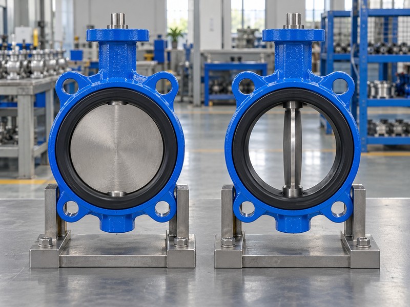
A disc rotates with its shaft to obstruct or open the pipe passage. That rotary movement explains how a butterfly valve works at its basic endpoints. In the simplified concentric arrangement shown here, the closed disc plane lies perpendicular to the flow axis, while the open disc plane lies approximately parallel to that axis.
Which reference makes the endpoints clear?
Use the pipe-flow axis and disc plane as the reference. Compare the same valve geometry. For this explanation, zero degrees means closed and ninety degrees means open; the actual drawing governs the model’s shaft indexing, stops and permitted travel. The disc remains attached to its shaft throughout the movement instead of withdrawing from the pipeline like a gate.
- Identify the pipe-flow axis in the drawing.
- Compare the closed and open disc planes.
- Use the selected model’s accepted travel endpoints.
Key takeaway: Read open and closed from the disc plane relative to the pipe, with the actual model drawing defining its accepted endpoints.
| Check | What you should confirm |
|---|---|
| Closed | Disc plane crosses the pipe-flow axis |
| Open | Disc plane lies approximately along the flow axis |
| Reference | Actual geometry and stops follow the model drawing |
2. What parts explain how a butterfly valve works?
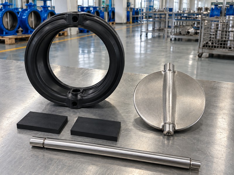
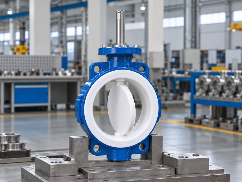
The body supports the assembly, the shaft transmits rotation, the disc changes the passage and the seat forms the closure interface. Together, those roles explain how a butterfly valve works. Bearings or bushings support the shaft, while the specified shaft seals control leakage around its penetration.
Where does the driving load travel?
Follow the operator connection into the shaft and the shaft’s actual connection with the disc. Inspect the section drawing. The selected design determines whether that connection uses pins, keys or another defined arrangement, and how it retains and supports the shaft. A body material certificate cannot identify the entire assembly; your material list should also identify the disc, shaft, seat and relevant auxiliary seals.
- Trace the operator, shaft and disc connection.
- Identify shaft support, retention and sealing features.
- Match each component with the approved material list.
Key takeaway: Use the section drawing to separate structural support, transmitted motion and sealing, with each part identified in the supplied configuration.
| Check | What you should confirm |
|---|---|
| Body | Supports the defined pressure-containing assembly |
| Shaft and disc | Transmit rotation through the specified connection |
| Seat and seals | Provide their respective closure and shaft sealing functions |
3. How does seat contact explain how a butterfly valve works?
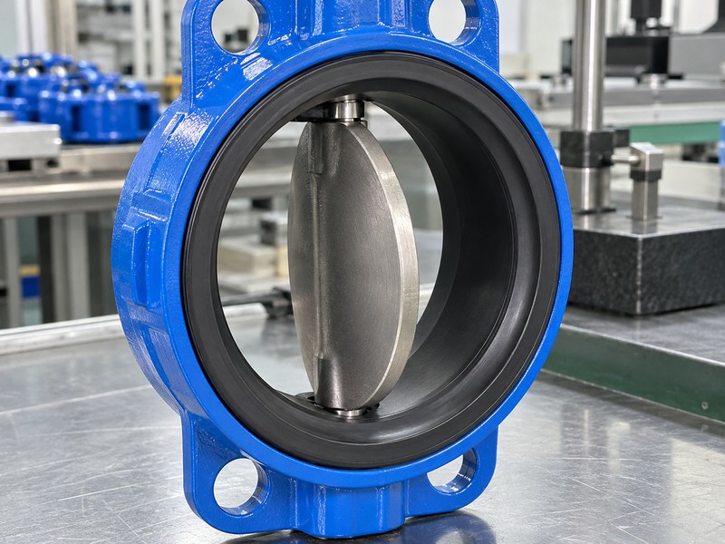
The disc meets the selected seat arrangement at closure to restrict passage through the valve. Seat geometry and material influence how a butterfly valve works, including contact, friction and the force needed near the closed position. An elastomer liner, polymer-lined construction and offset sealing arrangement require their own section details and acceptance basis.
What should you inspect in the sealing path?
Compare the disc edge, seat profile and retained position with the approved construction. Follow the complete contact path. A visibly closed disc does not establish the agreed leakage result, and a catalogue material name cannot prove compatibility with your complete fluid mixture. Keep the actual compound or resin, backing and shaft seals identified where applicable.
- Match disc contact with the actual seat profile.
- Identify wetted materials and auxiliary sealing components.
- Separate physical closure from leakage acceptance evidence.
Key takeaway: Seat contact explains the closure mechanism, while the selected materials and inspection conditions establish the accepted service and sealing scope.
| Check | What you should confirm |
|---|---|
| Contact | Disc and seat match the approved construction |
| Material | Complete wetted configuration fits the reviewed fluid |
| Acceptance | Defined leakage conditions have their own evidence |
4. How does flow relate to how a butterfly valve works?
Rotating the disc changes the available passage, but the open disc and shaft still occupy part of the bore. Flow and pressure loss are separate parts of understanding how a butterfly valve works. A half-open travel indication cannot establish half the system flow, and full opening cannot establish zero hydraulic obstruction or pressure loss.
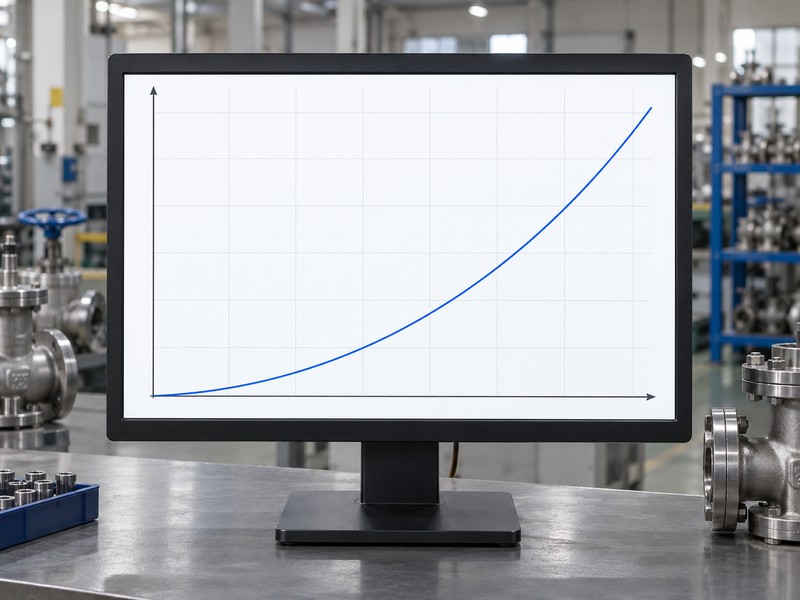
What does the conceptual pressure-loss curve show?
The illustration holds the liquid density and flow coefficient fixed while increased flow requires increased pressure loss. Use the actual operating data. Your model’s size, opening, coefficient, fluid properties and system pressures determine the applicable calculation, including any viscosity or cavitation review. A fixed-coefficient curve cannot represent every disc angle, and gas duty requires its own compressible-flow inputs and sizing method.
- Separate shaft angle, available passage and measured flow.
- Request model data for the intended opening.
- Review actual fluid properties and pressure conditions.
Key takeaway: Use actual valve and system data for selection; the conceptual curve illustrates a defined hydraulic relationship.
| Check | What you should confirm |
|---|---|
| Position | Disc travel identifies a mechanical opening |
| Coefficient | Actual model and opening determine the data |
| System flow | Operating pressures and fluid properties remain required |
5. Why does torque affect how a butterfly valve works?
Torque must overcome the valve’s mechanical resistance and fluid-induced loads throughout the stroke. Those loads influence how a butterfly valve works under actual pressure, seat and installation conditions. Breakaway, running and seating requirements can differ, so a valve that moves freely without process load may still need a different drive assessment for service.
Which inputs belong in the drive calculation?
RUITO evaluates the selected valve’s operating torque and closing differential alongside its interfaces and duty. Trace the calculation inputs. Include the actual seat configuration, fluid conditions, required movement and shaft or coupling limits, then compare demand with available output at the stated drive conditions. An unloaded movement cannot replace that stroke-specific sizing basis.
- Identify breakaway, running and seating torque conditions.
- Use the actual closing differential and fluid duty.
- Compare demand with available output across the stroke.
Key takeaway: Torque selection connects the rotary mechanism with the loads and drive conditions the complete assembly must handle in its accepted duty.
| Check | What you should confirm |
|---|---|
| Demand | Actual seat, differential and operating conditions used |
| Transmission | Shaft and coupling loads remain within their limits |
| Drive | Available output covers the specified movement conditions |
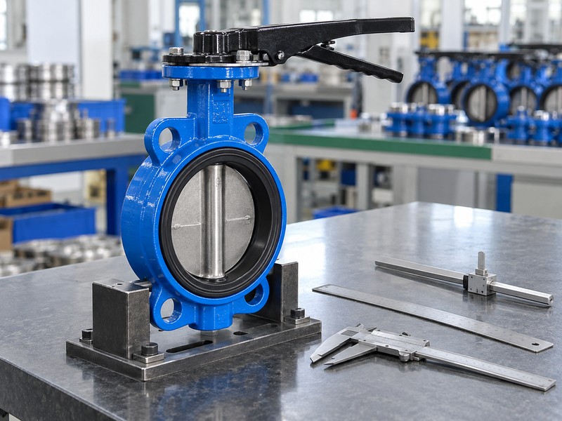
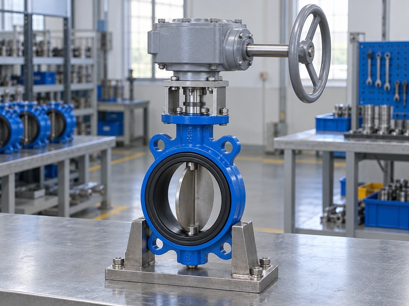
6. Where does gearing fit in how a butterfly valve works?
A gearbox transmits handwheel input through its gears to the rotary valve shaft. Understanding how a butterfly valve works with a gearbox requires separating handwheel input from shaft output. The handwheel’s rotations depend on the selected gearing; quarter-turn valve output does not mean a quarter-turn handwheel input.
What should the operator information identify?
A worm gearbox has its own input shaft, gear train, output connection, indication and travel limits. Follow the output connection. Match its mounting and permitted output with the valve, and use the selected instructions for turning direction, position indication and any stop setting. Self-locking or position-holding behaviour must come from the actual operator specification, and a mechanical stop cannot diagnose a mismatched disc position.
- Separate handwheel rotation from valve-shaft travel.
- Match gearbox mounting and output with the valve.
- Use selected instructions for direction, indication and limits.
Key takeaway: A geared valve retains rotary disc motion, with the selected transmission determining how the handwheel delivers that movement.
| Check | What you should confirm |
|---|---|
| Input | Handwheel movement follows the selected gear ratio |
| Output | Shaft movement follows the accepted valve travel |
| Indication | Pointer and limits match the actual assembly |
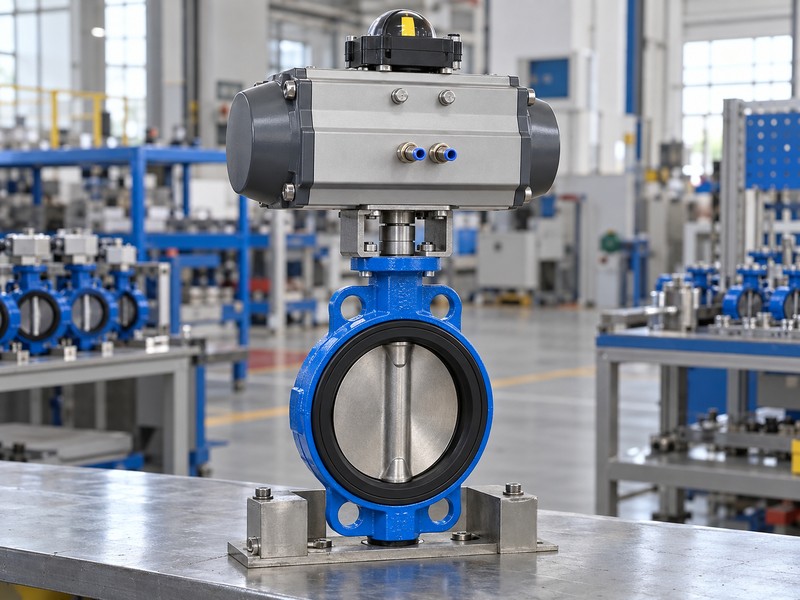
7. How does actuation affect how a butterfly valve works?
An electric or pneumatic actuator supplies the shaft rotation that a manual operator would otherwise provide. The actuation choice affects how a butterfly valve works through available torque, command handling and the assembly’s specified action. It does not change the valve’s wetted materials, pressure-temperature limits or permitted hydraulic duty merely by adding automation.
Which functions need the selected assembly documents?
Confirm the actual actuator, mounting, coupling and any feedback or positioner functions with their manuals. Check the complete drive conditions. Available output must suit the valve demand through the required stroke, including the applicable minimum supply and return conditions. Review air loss, signal loss and electrical-power loss separately; neither a universal endpoint nor a manual-override function follows from the word automatic.
- Identify the actual actuator and supplied control functions.
- Compare output with demand at the stated supply.
- Define each required loss-event action separately.
Key takeaway: Automation supplies shaft movement; the selected valve and accessory documents define the assembly’s permitted functions and duty.
| Check | What you should confirm |
|---|---|
| Mechanical | Actuator and coupling fit the accepted valve |
| Supply | Torque assessment uses actual drive conditions |
| Function | Commands, feedback and loss events are documented |
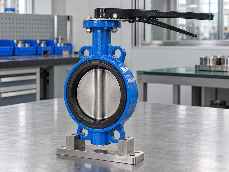
8. Why does design change how a butterfly valve works?
Concentric and offset layouts change the shaft-disc-seat geometry and how sealing surfaces meet or disengage. That geometry changes aspects of how a butterfly valve works without replacing rotary motion. A concentric valve centres the shaft and disc within the bore, while a double-offset arrangement displaces the relevant axes and changes the opening contact path.
What should you compare between constructions?
Use each section drawing to locate the shaft, disc and sealing surface. Compare the geometry directly. Double-offset layouts use two positional offsets, while triple-offset designs add angular or conical sealing geometry without a universal distance or cone angle. RUITO’s documented concentric and double-offset configurations retain their own materials and ratings; the general explanation cannot establish another construction’s supply or performance.
- Locate shaft axes and sealing surfaces on drawings.
- Compare actual seat engagement and opening geometry.
- Keep construction-specific materials and ratings identified.
Key takeaway: Read construction differences through their actual geometry and sealing arrangement, with the model’s documents defining the claimed operating scope.
| Check | What you should confirm |
|---|---|
| Concentric | Shaft and disc follow the centred geometry |
| Offset | Specified displacements change the contact path |
| Selection | Actual construction determines its material and rating scope |
9. What service limits apply to how a butterfly valve works?
Materials, temperature, working pressure, closing differential and installation conditions bound the selected valve’s duty. Apply those limits when explaining how a butterfly valve works for a real process. RUITO’s ordinary clean-water configurations use 5–60°C service and their actual PN10/16 pressure-temperature rating; other fluids, sealing materials and applications require their own reviewed configurations.
Which apparent similarities can hide different duties?
An identical connection shape can contain a different seat compound, lining or shaft-seal arrangement. Check the full material schedule. Flow in either direction cannot establish equal shutoff differentials, and the double-offset direction limits remain separately declared. Continuous throttling needs the selected model’s accepted operating envelope and hydraulic review; intermediate positioning, a gearbox or a positioner cannot supply that qualification on its own.
- Use one accepted material and pressure-temperature configuration.
- Separate flow direction from permitted closure differential.
- Review continuous throttling as a model-specific duty.
Key takeaway: Duty depends on the selected materials, ratings, interfaces and documented operating envelope.
| Check | What you should confirm |
|---|---|
| Materials | Complete wetted configuration fits the actual fluid |
| Pressure | Working and directional closure limits remain separate |
| Operation | Accepted envelope covers the intended operating function |
10. What records verify how a butterfly valve works?
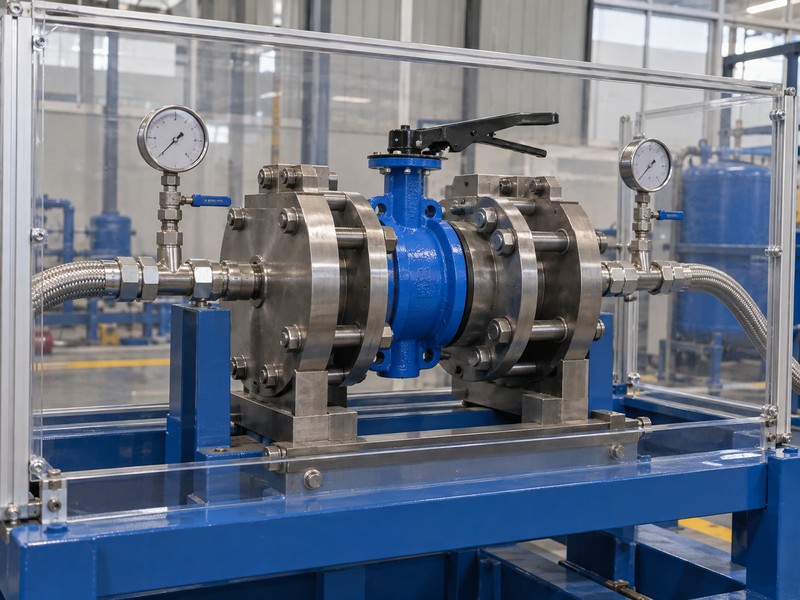
Drawings, identified component records and the agreed functional and pressure inspections verify different aspects of the supplied valve. To verify how a butterfly valve works, connect observed motion with the accepted assembly and keep leakage evidence separate. A rotating sample can demonstrate movement, while the required sealing result needs a defined test method and recorded conditions.
What should the acceptance package distinguish?
Use the approved inspection plan to identify dimensions, travel, materials and required pressure checks. Match the product ID. A method such as ISO 5208 addresses its specified pressure-testing scope, with the actual medium, direction and acceptance conditions recorded. Inspection pressure cannot become working pressure, and a management certificate cannot establish every product approval or market scope; verify any required approval against its exact coverage.
- Connect drawings and results with the actual product ID.
- Separate movement, pressure and approval evidence.
- Retain test conditions and the applicable acceptance decision.
Key takeaway: Connect the supplied construction and observed movement with the defined sealing evidence.
| Check | What you should confirm |
|---|---|
| Mechanism | Drawing and functional checks identify actual motion |
| Sealing | Agreed pressure records define their conditions and result |
| Approval | Required product coverage matches the supplied configuration |
Send RUITO your fluid, operating conditions, installation drawing and required operating function. We can identify the proposed construction and the material, drive and inspection questions that need review. Contact us to connect the valve mechanism with the evidence required for your actual enquiry.
FAQ
Q1: Can I tell the valve position from its handle alone?
Only after checking its indexing. Compare the selected assembly’s indication and shaft connection with the accepted physical disc position.
Q2: What’s the difference between disc angle and flow?
Angle is mechanical travel. Actual flow also depends on the valve’s opening-specific coefficient, fluid properties and system pressure conditions.
Q3: Can a fully open butterfly valve have pressure loss?
Yes. The disc and shaft remain in the bore, so use the actual model data and flow conditions to evaluate the loss.
Q4: How do I know how many times to turn the handwheel?
Use the selected gearbox information. Its gearing determines input rotations for the valve’s accepted output stroke.
Q5: Can I use any butterfly valve for continuous throttling?
No. Obtain the specific construction’s approved operating envelope and hydraulic review; intermediate positioning alone cannot establish suitability.