
Fix operating-check mistakes by tracing operator input to observed shaft and disc response under the accepted installation and duty. Use “how does a butterfly valve work” as the inspection worksheet title. Connect observations with the actual assembly, selected instructions and acceptance conditions; movement alone cannot establish fit, sealing or process suitability.
If an indicator reaches closed while a misindexed disc remains short of its seat, the valve may pass a casual movement check and fail the project’s acceptance requirement. Turning harder can conceal the real interface or stop problem. Qualified personnel should authorize isolation and movement, then record any mismatch before release.
1. During an isolated check, how does a butterfly valve work?
The operator must move the actual shaft and disc through their accepted range under an authorized, isolated check. Use “how does a butterfly valve work” as the worksheet title and record the assembly ID, approved drawing and procedure. Identify the accepted endpoints before operating the drive.
Which physical references belong in the record?
In a simplified concentric valve, the closed disc plane crosses the flow axis and the open plane lies approximately parallel to it. Compare the model drawing. Confirm its actual shaft indexing and travel reference before interpreting a pointer, handle or display. The illustrations explain the check; they cannot establish the condition or movement of the valve your project receives.
- Identify the assembly and selected operating procedure.
- Authorize isolation and movement before the check.
- Record physical disc references and accepted endpoints.
Key takeaway: An operating check needs an identified assembly, authorized movement and a physical reference for the endpoints your team intends to verify.
| Check | What you should confirm |
|---|---|
| Identity | Observed unit matches its drawing and procedure |
| Authorization | Qualified team defines isolation and permitted movement |
| Endpoints | Physical disc positions match the accepted references |
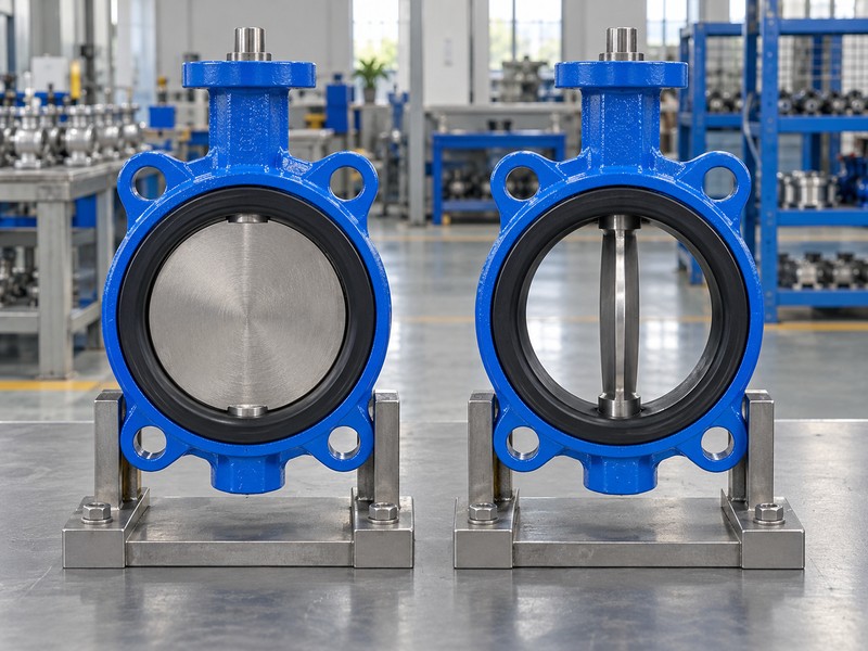
2. Inside the installed pipe, how does a butterfly valve work?
The disc must rotate without contacting the mating pipe, flange bore or nearby internal obstruction. In the “how does a butterfly valve work” check, compare the complete disc sweep with the actual installation. Nominal size alone cannot establish that clearance, especially where lined pipe, reducers or a different flange bore changes the available space.
What should you verify before interpreting resistance?
Compare the approved valve drawing with the installed flange, pipe bore and support arrangement. Follow the moving envelope. Use the selected seat-compression and gasket instructions, since extra gasket material or an incorrect interface can distort the intended assembly. If movement binds, record the interference for review before changing stops or drive force.
- Compare disc sweep with the actual pipe bore.
- Check flange, support and seat-compression requirements.
- Investigate binding before changing force or travel settings.
Key takeaway: A valve’s observed movement is meaningful only when its installed interfaces allow the accepted disc travel without unexplained contact or distortion.
| Check | What you should confirm |
|---|---|
| Clearance | Disc clears the actual mating installation |
| Joint | Gasket and seat conditions follow the model instructions |
| Movement | Any interference is identified and resolved |
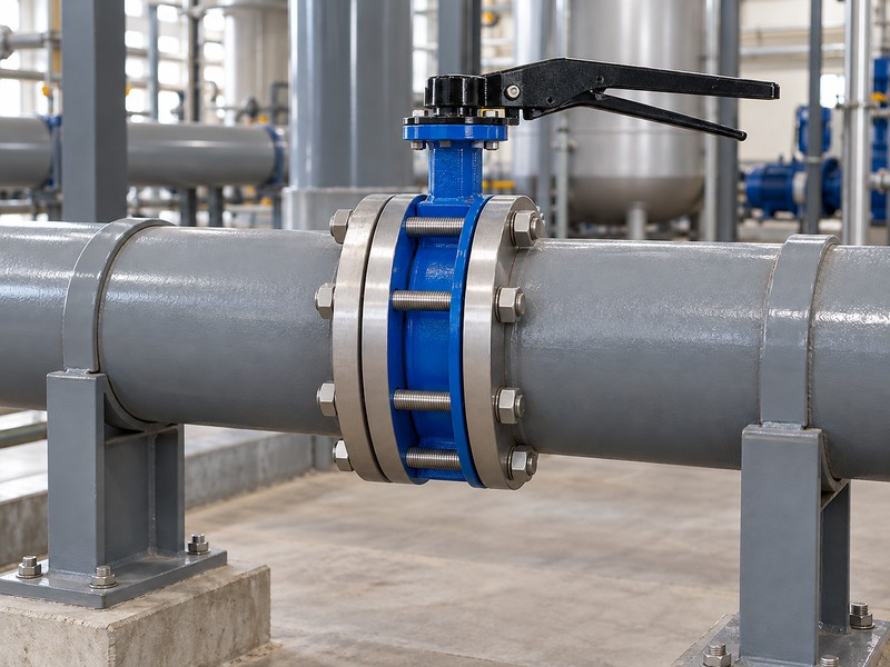
3. With wafer or lug joints, how does a butterfly valve work?
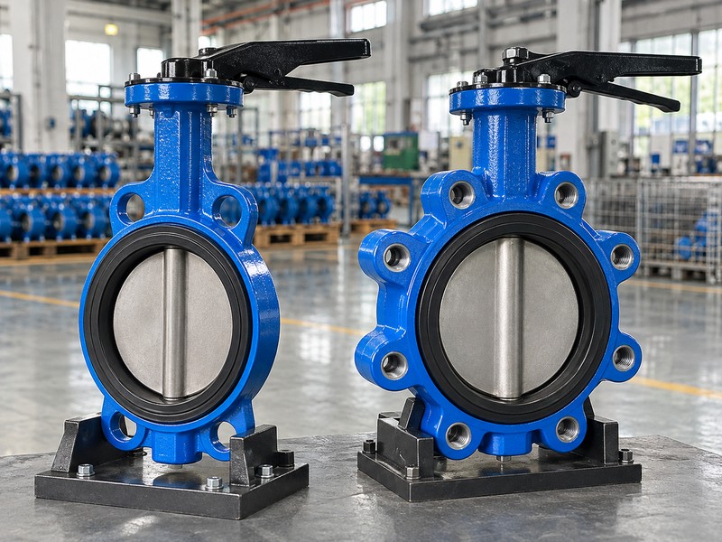
The disc still rotates, while the selected connection determines how the body mounts and carries its installation loads. Your “how does a butterfly valve work” worksheet should identify that connection and its approved joint details. Use each connection’s actual drawing; the body name cannot establish end-service duty or interchangeable dimensions.
Which lug-service conditions need separate evidence?
Check the specified thread engagement, bolt arrangement and applicable end loads for the actual lug model. Review end service separately. RUITO’s special clean-water lug end-service configuration is limited to DN50–200, 5–40°C and a declared closing differential no greater than 10 bar, with independent verification required. That scope cannot transfer to every lug body or replace the project’s accepted installation and inspection conditions.
- Identify the exact connection and installation drawing.
- Check bolt engagement and applicable support loads.
- Require separate evidence for any proposed end service.
Key takeaway: Compare the connection’s physical and rated conditions with your installation instead of inferring isolation capability from a lug-shaped body.
| Check | What you should confirm |
|---|---|
| Connection | Actual body and joint details match the drawing |
| Loads | Bolts, engagement and support conditions are checked |
| End service | Exact configuration and separate acceptance scope are verified |
4. With a handwheel gearbox, how does a butterfly valve work?
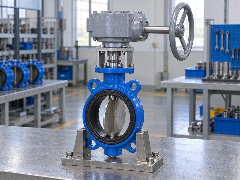
The handwheel turns a gear train that rotates the valve shaft through its accepted output travel. Record gearbox input and valve output separately in the “how does a butterfly valve work” check. A quarter-turn valve stroke cannot supply a universal handwheel turn count, and the selected operator information governs direction, indication and travel limits.
What observations connect the handwheel with the disc?
Trace the gearbox output and coupling to the actual valve shaft before accepting its pointer position. Check the selected instructions. Record whether observed disc endpoints agree with the approved assembly, and review any holding or self-locking claim against the actual gearbox specification. Reaching a handwheel limit cannot establish sealing, nor authorize additional force or an undocumented stop adjustment.
- Separate input rotations from valve-shaft travel.
- Check coupling and pointer indexing against physical endpoints.
- Use the actual operator’s direction and limit instructions.
Key takeaway: Verify handwheel-to-disc movement and the gearbox’s documented direction, gearing and limits.
| Check | What you should confirm |
|---|---|
| Input | Handwheel movement follows the selected gearing |
| Output | Valve shaft reaches its accepted travel references |
| Limits | Indication and stop conditions match the assembly |
5. With a powered actuator, how does a butterfly valve work?
The actuator must transmit its commanded movement through the mounting and coupling to the actual valve shaft. For “how does a butterfly valve work” acceptance, compare command, observed travel and any supported feedback as separate observations. An automatic drive does not establish a manual-override function, a universal failure endpoint or suitability for every valve duty.
Which operating functions should the reviewer identify?
Use the selected actuator and accessory manuals to define supply, direction and required functions. Follow the actual connection. Check feedback indexing and the physical movement recorded under the agreed conditions, then review air loss, signal loss and power loss as separate events where applicable. A positioner indicates shaft travel; any process-flow control claim needs the relevant measurement, controller and hydraulic acceptance evidence.
- Identify supported commands, supplies and feedback functions.
- Compare indicated movement with the actual valve response.
- Define required loss events and process-control evidence separately.
Key takeaway: Record the command, supply and observed valve movement, with supported functions limited to their documented scope.
| Check | What you should confirm |
|---|---|
| Drive | Mounting and coupling transmit the accepted movement |
| Feedback | Supported indication matches its physical reference |
| Functions | Required normal and loss-event actions are documented |
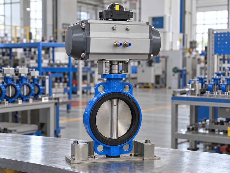
6. Under the specified load, how does a butterfly valve work?
The drive must supply the valve’s required torque throughout the accepted stroke under the specified load. Keep the “how does a butterfly valve work” check tied to the actual seat, fluid, closing differential and drive conditions. A freely moving unloaded sample cannot establish the same movement under the pressure and installation conditions your project will impose.
What should the torque and movement records distinguish?
Compare demanded and available torque with the stated operating conditions and applicable shaft or coupling limits. Review the complete stroke. The actuator assessment needs its actual minimum supply and any required return conditions, while the movement record should identify whether load was present. Investigate unexpected resistance against the installation, seat and coupling records before changing drive force.
- Use actual duty and closing-differential inputs.
- Compare torque demand and output across the stroke.
- Distinguish unloaded checks from required loaded movement.
Key takeaway: Loaded operating acceptance requires the actual torque basis and relevant verification conditions, with an unloaded demonstration retaining its narrower scope.
| Check | What you should confirm |
|---|---|
| Demand | Seat, fluid and differential match the accepted duty |
| Output | Actual minimum drive conditions are identified |
| Evidence | Movement record states the load and inspected configuration |
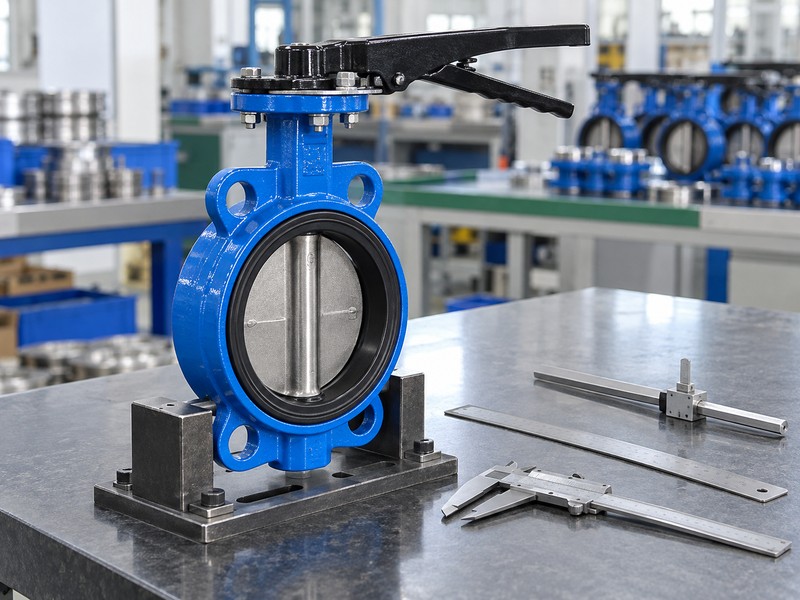
7. During a closure check, how does a butterfly valve work?
The drive brings the disc into its accepted closed position and the selected seat-contact arrangement provides the closure interface. In a “how does a butterfly valve work” inspection, compare that physical endpoint with the indication and approved drawing. Visible closure verifies a movement condition; it cannot establish the leakage result required by your acceptance plan.
Which observations need their own sealing evidence?
Record disc indexing, travel limits and relevant seat-contact findings for the actual unit. Follow the inspection boundary. Keep shaft external leakage separate from closed-seat leakage, and use the agreed medium, pressure, direction, duration and criterion for any required pressure check. A damaged seat or misindexed stop needs a documented correction and applicable reinspection rather than an assumption that extra closing effort will resolve it.
- Verify physical closure against the accepted indication.
- Separate seat closure from shaft external-leakage checks.
- Record required conditions and any authorized corrective work.
Key takeaway: Verify physical closure, then connect the required sealing decision with its defined inspection evidence.
| Check | What you should confirm |
|---|---|
| Position | Disc and indication match the accepted closed reference |
| Seat | Required closure evidence states its test conditions |
| Shaft | External-leakage acceptance remains a separate check |
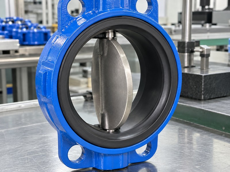
8. At intermediate travel, how does a butterfly valve work?
The disc leaves a restricted passage whose actual flow depends on opening-specific valve data and the system conditions. The “how does a butterfly valve work” worksheet should separate travel indication from measured flow and pressure loss. Half the accepted travel cannot establish half the flow, and an intermediate-position function alone cannot qualify continuous throttling.
What should the hydraulic acceptance review use?
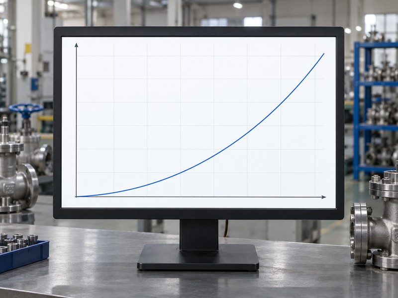
Request the model’s coefficient data and approved operating range for the intended fluid and opening. Compare the real duty. The conceptual curve fixes coefficient and liquid density while pressure loss rises with flow; it does not represent every disc angle or a measured valve result. Actual sizing also needs pressure conditions and relevant fluid properties, with cavitation, noise or viscosity reviewed as the duty requires.
- Record mechanical travel and process measurements separately.
- Use actual model data for the intended opening.
- Review the permitted continuous operating envelope.
Key takeaway: Record intermediate travel as movement and use model-specific hydraulic data to assess the proposed flow duty.
| Check | What you should confirm |
|---|---|
| Travel | Position identifies a mechanical opening only |
| Hydraulics | Fluid, coefficient and pressure conditions support selection |
| Duty | Accepted envelope covers the proposed throttling use |
9. With reversed pressure, how does a butterfly valve work?
The same disc rotates, but permitted closure differential may change with the higher-pressure side and the selected sealing construction. Record those conditions in the “how does a butterfly valve work” check. Fluid passage in both directions cannot establish equal shutoff ratings, and an installation arrow must be interpreted through the actual model’s approved documents.
Which pressure fields should the reviewer keep separate?
Identify normal flow, any preferred installation direction and the accepted closing differential for each required pressure direction. Check the actual rating. RUITO’s double-offset configuration declares forward and reverse closing differentials separately; its ordinary clean-water configurations use 5–60°C and the actual PN10/16 pressure-temperature basis. Keep working, transient and inspection conditions in separate fields.
- Identify flow and higher-pressure sides separately.
- Verify each required directional closing differential.
- Keep working, transient and inspection conditions distinct.
Key takeaway: Reversed pressure needs the actual model’s directional closure scope and an inspection record that identifies which side received pressure.
| Check | What you should confirm |
|---|---|
| Flow | Expected passage direction matches the installation review |
| Closure | Each required differential fits the actual model rating |
| Pressure basis | Working and inspection conditions retain separate meanings |
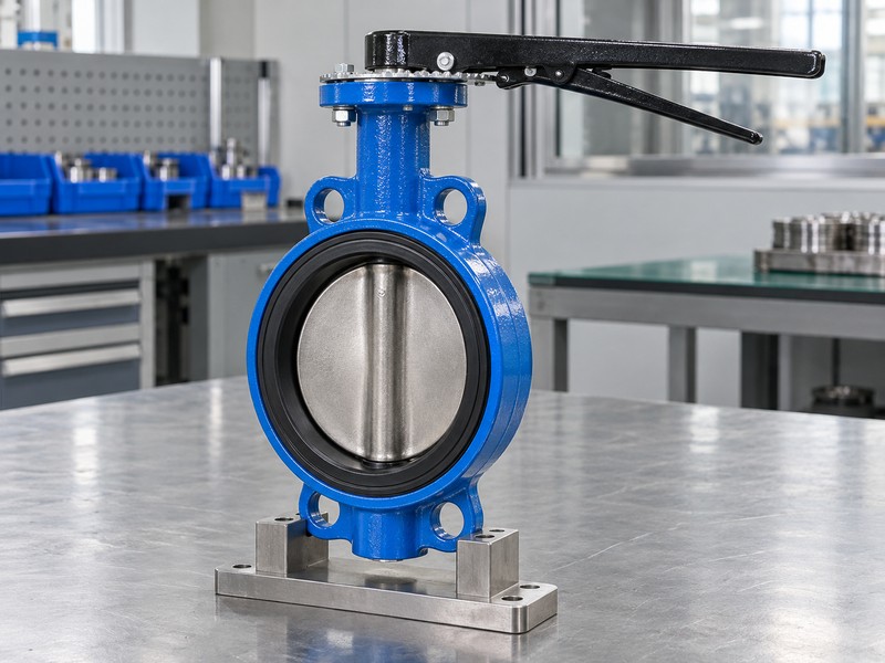
10. During acceptance, how does a butterfly valve work?
The valve must reproduce the accepted movement under the stated check conditions, while separate pressure evidence establishes its specified integrity and closure results. Close the “how does a butterfly valve work” worksheet with those evidence categories identified. Your decision should connect the actual product, configuration and drawing revision with the observations required by the inspection plan.
What makes the acceptance decision traceable?
Retain the assembly ID, inspection method, instrument references, conditions, findings and authorized corrective decisions. Review the pressure records separately. An agreed method such as ISO 5208 covers its specified pressure-testing scope, without establishing control accuracy or increasing working-pressure limits. Keep required product approvals tied to their exact model and destination scope, then release the accepted unit only after its required records and findings close.
- Link observations and records with product identity.
- Separate functional, pressure and approval evidence.
- Close required findings and retain authorized reinspection results.
Key takeaway: A traceable operating decision states what the identified valve demonstrated and which separate records establish its remaining acceptance requirements.
| Check | What you should confirm |
|---|---|
| Function | Observed movement matches the agreed conditions and revision |
| Pressure | Required results identify medium, direction and acceptance basis |
| Release | Product identity and required findings connect with the decision |
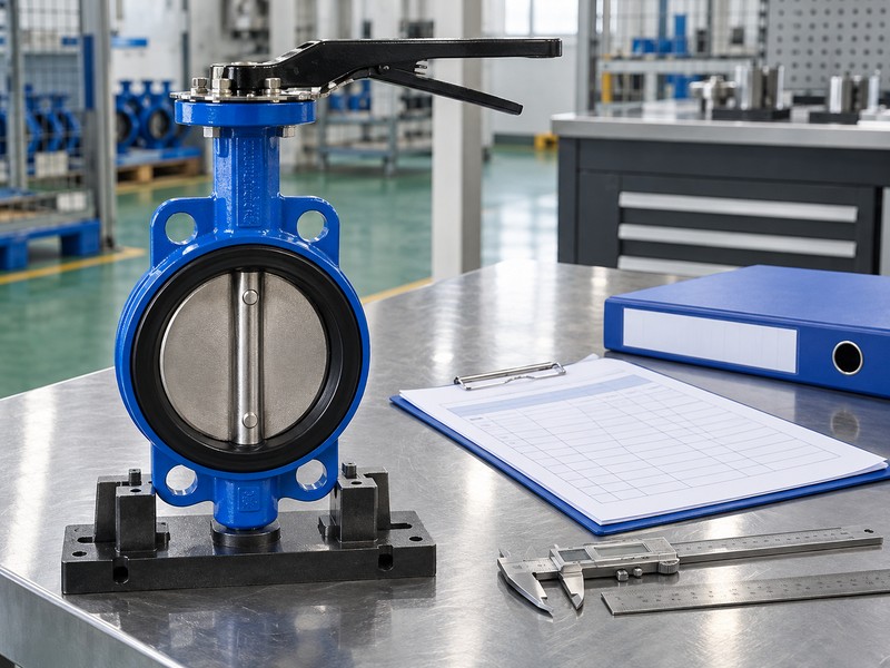
Send RUITO your installation drawing, service sheet, drive requirements and proposed operating checklist. We can review the configuration and identify the interface, torque and inspection evidence needed for your acceptance plan. Contact us before releasing the valve for installation or approving an unresolved operating condition.
FAQ
Q1: Can I accept a closed pointer as proof that the valve seals?
No. Verify physical indexing and the required pressure-test result separately; the pointer identifies an indicated position.
Q2: What’s the best way to investigate unexpected operating resistance?
Hold the finding for review. Compare installation clearance, seat conditions, coupling and the actual torque basis before changing force or stops.
Q3: How do I know whether the gearbox needs several turns?
Check its selected instructions. Handwheel input movement depends on gearing, while the valve follows its accepted output stroke.
Q4: Can I assume a lug valve works at a pipe end?
No. Verify the exact end-service configuration, installation loads, pressure differential and independent acceptance evidence before approving that use.
Q5: Can the same functional check prove reverse-pressure sealing?
No. Reverse-pressure closure needs its own applicable model rating and the agreed pressure-test evidence for that direction.