
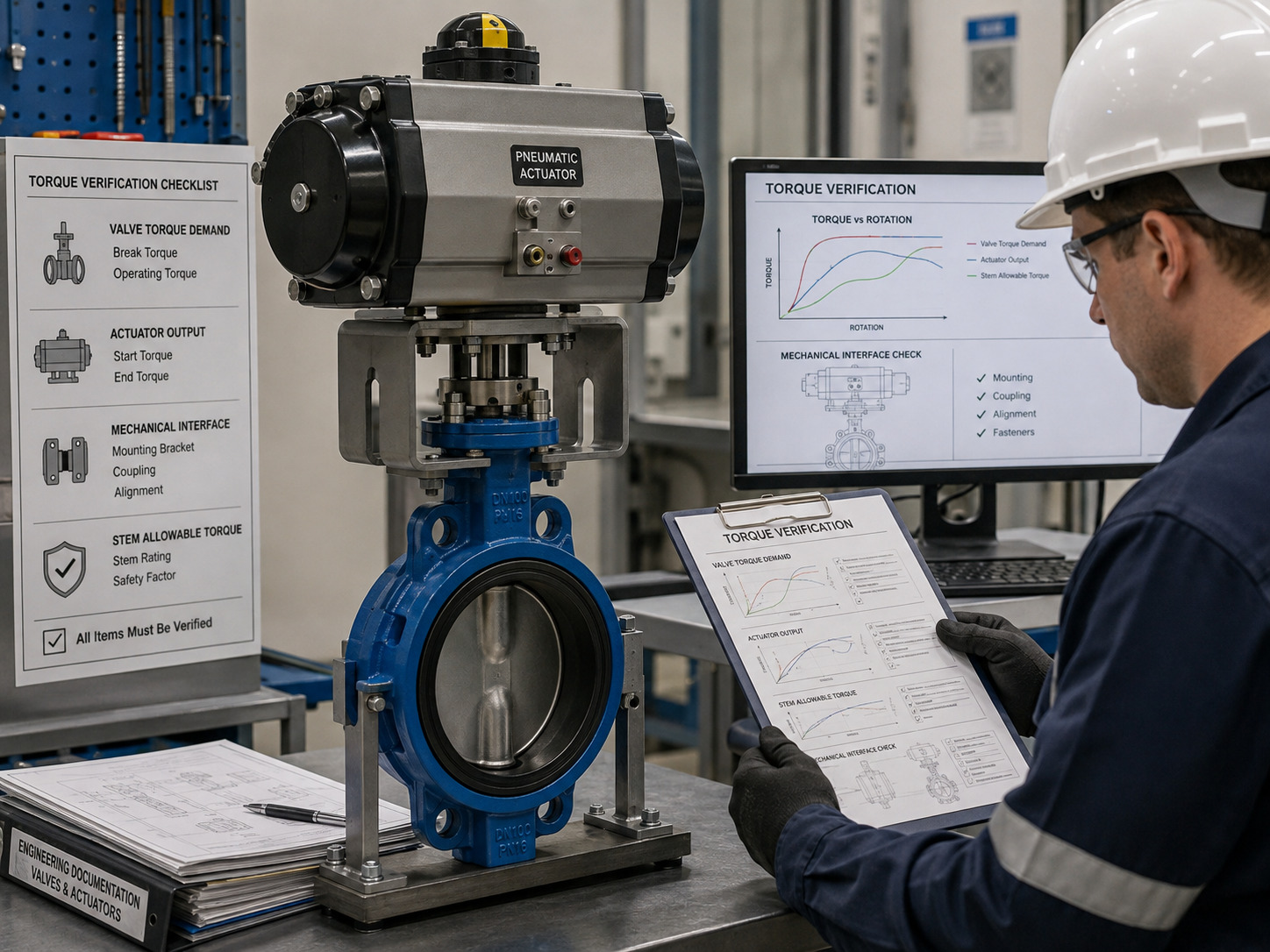
A butterfly valve torque chart is reliable for actuator sizing only when its valve series, seat, differential pressure, service conditions, torque definitions, and safety-factor basis match your application. A DN-to-Nm table without those conditions is a preliminary reference, not an actuator selection document.
This matters when an apparently adequate actuator stalls at breakaway, loses margin midway through travel, or drives the disc into the seat with more torque than the stem can safely transmit. The practical solution is to treat the chart as one part of a valve-actuator acceptance check. Start with the selected industrial butterfly valve configuration, then verify demand, actuator output, and every mechanical torque limit on the same basis.
Read the chart assumptions before reading the torque value
The chart is usable only if its header and notes identify the conditions behind the number. Find the row for the exact valve series and size, then read across the correct seat, differential-pressure, medium, temperature, and operating-direction columns.
Use this gate before transferring any number into an actuator schedule:
| Chart field | What you need to confirm | Reject or limit the chart when |
|---|---|---|
| Valve identity | Manufacturer, series, size, body style, offset design | It lists only DN or NPS |
| Sealing system | Seat material, seat construction, shutoff direction | The seat differs from the ordered valve |
| Pressure basis | Maximum differential pressure, not merely line rating | Only PN or ASME Class is shown |
| Service basis | Medium, wet or dry condition, temperature, cleanliness | The test basis is absent or unlike the service |
| Torque definition | Unseating, running, dynamic, seating, or maximum operating torque | A single value is labeled only “torque” |
| Units and location | N·m, lbf·in, or lbf·ft at the valve shaft | Units or measurement location are unclear |
| Margin treatment | Whether a service or safety factor is already included | The factor is unstated |
| Direction and angle | Opening or closing direction and disc position | No stroke position is identified |
The critical point is the pressure basis. Pressure class tells you what the valve body is rated to contain; differential pressure is the load actually acting across the closed or throttled disc. Do not substitute one for the other.
Identify the torque that governs each part of the stroke
Actuator sizing must cover the highest required torque at the corresponding stroke position, not simply the largest number printed anywhere on the sheet. A butterfly valve parts diagram helps trace the load from the disc and seat through the shaft, bearings, coupling, bracket, and operator.
The common chart labels have different meanings:
| Torque term | Where it matters | Typical source of resistance |
|---|---|---|
| Unseating or breakaway torque | Leaving the fully closed position | Disc-seat contact, packing, bearings, deposits, standstill |
| Running torque | Moving through the stroke | Bearings, packing, residual seat contact, process resistance |
| Dynamic torque | Partially open under flow | Hydrodynamic force on the disc; direction can assist or oppose motion |
| Seating torque | Entering the closed position | Seat interference and the required shutoff load |
For an isolation valve, unseating or seating torque may govern. For a throttling valve, the dynamic peak at an intermediate angle may govern instead. You therefore need torque by stage or angle whenever flow acts on the disc during operation.
Treat every generic torque table as a preliminary screen
Generic values cannot be transferred safely between butterfly valve designs because seat geometry, shaft size, bearings, disc profile, pressure direction, media, and temperature all change the torque curve. Even two valves with the same nominal size and pressure class can require different operators.
A useful engineering model is:
Tvalve(θ) = Tseat(θ) + Tbearing + Tpacking + Tdynamic(θ)
Here, θ is disc angle. This is a load map, not a universal calculation formula: the components and their signs must come from design data, test results, or a validated manufacturer model. Dynamic torque deserves separate attention because butterfly valve flow characteristics change with disc angle and actual pressure drop.
Use a generic chart only to compare orders of magnitude or prepare an early equipment layout. Before purchase, replace it with a revision-controlled chart for the ordered valve series and service basis.
Match valve demand to actuator output across the stroke
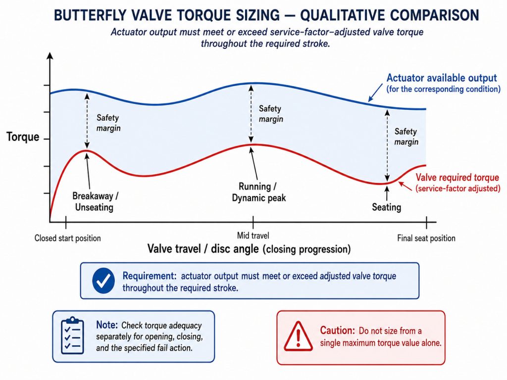
The actuator passes only when its available output exceeds the factored valve demand at every relevant position and direction. A single nameplate torque comparison can miss a weak point, especially for spring-return pneumatic actuators whose output changes through the stroke.
Apply this sequence:
- Record valve torque at closed breakaway, intermediate running or dynamic peaks, and final seating.
- Define the worst credible operating case: maximum differential pressure, minimum pneumatic supply or low-voltage condition, temperature, media state, fail direction, and required operating time.
- Confirm whether the valve chart already includes a service factor. Apply the project-approved factor once, not twice.
- Obtain the actuator output curve at the stated supply pressure, spring set, voltage, frequency, and temperature.
- Compare matching points using
Tactuator available(θ) ≥ Tvalve(θ) × service factor. - Repeat the check for opening, closing, and the specified fail action.
For pneumatic packages, the pneumatic actuator selection workflow is the next useful check after the valve torque basis is established. For electric or hydraulic units, use the corresponding certified output data and duty limits rather than assuming the same torque profile.
Oversizing is not a substitute for this comparison. Excess actuator torque can overload the shaft, key, coupling, bracket, mounting flange, or seat if the valve jams or the stops are misadjusted.
Keep demand, output, interface, and stem limits separate
A reliable assembly must satisfy four different torque checks: valve demand, actuator availability, interface capacity, and valve component capacity. Combining them into one “torque rating” hides failure modes.
| Check | Acceptance question | Failure if ignored |
|---|---|---|
| Valve required torque | Can the actuator move and seat the valve under the defined service? | Stall, incomplete shutoff, slow travel |
| Actuator available torque | Is adequate output available at each stroke point under the worst supply condition? | Mid-stroke or fail-action loss of margin |
| Interface and coupling torque | Can the flange, drive, bracket, and coupling transmit the actuator load? | Deformation, looseness, coupling or bracket failure |
| Maximum allowable stem torque | Can the shaft and drive train survive maximum or stall output? | Twisted stem, damaged keyway, disc misalignment |
ISO 5211:2026 specifies part-turn actuator attachment dimensions, drive-component dimensions, and reference torques for interfaces and couplings. That scope does not make an ISO 5211 flange designation a valve-operating torque chart. Mechanical fit and operating capacity remain separate approvals.
ISO 5115:2023 addresses actuated valve assemblies and the information and responsibilities needed for actuator and mounting-kit sizing, selection, and assembly. This supports an assembly-level review: the valve, actuator, bracket, coupling, and operating case must be accepted together.
Build a procurement-ready torque record
A procurement-ready torque chart identifies the product and assumptions well enough for another engineer to reproduce the selection. It should travel with the actuator calculation, interface drawing, and approval revision rather than appearing as an isolated catalog screenshot.
At minimum, record:
- Valve manufacturer, model or series, size, pressure class, body style, offset type, seat, shaft, and flow direction.
- Medium, solids or viscosity where relevant, minimum and maximum temperature, maximum shutoff differential pressure, and operating differential pressure.
- Unseating, running, dynamic, and seating torque by direction and disc angle.
- Test or calculation basis, wet or dry condition, units, tolerances, and whether margin is included.
- Actuator model, action, output curve, minimum supply or voltage basis, duty, speed, fail position, and service factor.
- ISO 5211 interface, coupling and bracket details, maximum allowable stem torque, stops, and torque-limiting settings.
- Document number, revision, date, preparer, reviewer, and approval status.
The evidence should also match the delivered valve. RUITO’s published butterfly-valve QC workflow records operating torque at 0°, 45°, and 90° and identifies a Torque Test Log as the deliverable. For an automated package, request that record with the final valve torque basis, actuator output data, and interface drawing so the approval is traceable to the supplied configuration.
Stop the sizing review when these warning signs appear
Pause the selection when the chart lacks a series number, pressure differential, seat, units, torque definition, or safety-factor statement. Those omissions prevent a defensible comparison, even if the table contains the valve size you need.
Also stop when the actuator sheet gives only maximum torque, when pneumatic output is quoted at nominal rather than minimum supply, or when the calculated output exceeds the stem or interface limit. Resolve the missing basis, request the correct curves, or require a witnessed torque test before releasing the package.
Field symptoms can reveal the same mismatch after installation: hesitation at breakaway, travel that slows at one angle, failure to reach the closed limit, repeated high-torque trips, a shifting bracket, coupling play, or a stem that springs back after the actuator stops. Do not raise torque settings until alignment, process load, seat condition, stops, and allowable component torque have been checked.
Turn the torque chart into an approved valve package
A butterfly valve torque chart becomes useful when it connects a defined valve and operating case to the actuator output curve, interface capacity, and stem limit. Read the assumptions first, compare torque at matching stroke positions, apply margin once, and preserve the calculation and test basis in the procurement record.
If your data is incomplete, you can still start with the valve size, medium, temperature, pressure or differential pressure, seat, actuator type, and fail position you know. Contact RUITO to review the missing inputs, confirm the required torque documentation, or prepare a valve-actuator specification for your project.
FAQ
Is butterfly valve operating torque the same as flange bolt torque?
No. Operating torque rotates the disc through the valve shaft, while flange bolt torque tightens the piping fasteners. They use different load paths, calculations, and acceptance criteria, so a bolt chart must never be used to size an actuator.
Why can a valve operate on the bench but stall in the pipeline?
Bench operation may have little or no differential pressure and a clean, lubricated seat. Installed service adds process pressure, flow-induced torque, temperature effects, deposits, misalignment, and sometimes lower actuator supply, any of which can consume the available margin.
What if actuator stall torque exceeds the stem limit?
The assembly is unacceptable unless a validated torque-limiting method keeps transmitted torque below the allowable stem and interface limits. Select a different actuator, change the gear ratio, or set and verify torque protection without sacrificing the output required at any stroke point.