
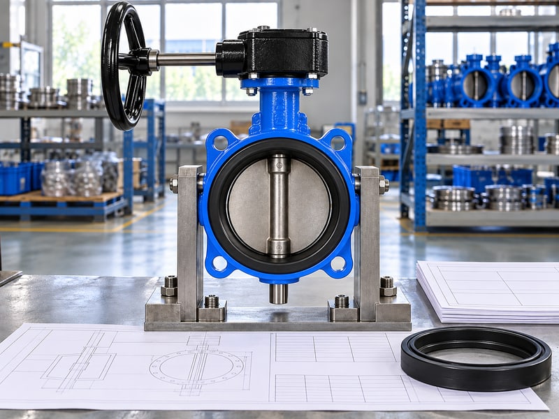
Fix butterfly valve preferred flow direction mistakes by matching the supplied valve's markings, shutoff limits and installation instructions with pressure on both sides of the closed disc. On a pump skid, a valve can fit the flanges yet face a pressure reversal that its purchase specification never addressed. Finding that gap during commissioning can delay handover and leave isolation performance unresolved. Build a direction check into selection, drawing approval and installation release so you can resolve the duty before operating the valve.
1. Why does butterfly valve preferred flow direction matter?
The butterfly valve preferred flow direction matters because the selected valve may have direction-specific shutoff limits. A valve that passes fluid both ways when open can still need a defined high-pressure side when closed. You need that distinction before approving a replacement or releasing a repeat order for another installation. Keep the valve's pressure designation separate from its maximum allowable closed differential.
What should your purchase specification settle?
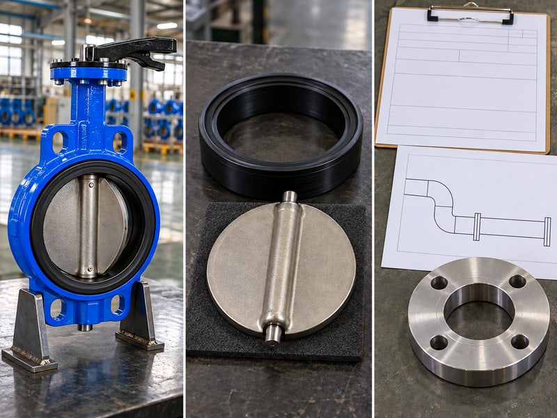
Start with the isolation duty. Ask the supplier to identify the pressure face, permitted differential pressure and leakage criterion for your exact size and seal configuration. A connection description such as wafer, lug or double flanged does not settle those questions. Record normal operation alongside credible shutdown and maintenance conditions, especially where a common header can remain pressurized after one branch stops.
- Specify the maximum closed differential from each side of the valve.
- State whether isolation must work with both pipe ends connected.
- Request directional limits in the approved data sheet and installation drawing.
| Procurement item | Evidence required |
|---|---|
| Shutoff direction | Model-specific pressure-face instruction |
| Reverse duty | Declared differential and leakage criterion |
Key takeaway: You can prevent an ambiguous purchase by making directional duty an acceptance item. Hold technical approval until both pressure conditions have an answer.
2. What sets butterfly valve preferred flow direction?
The manufacturer sets butterfly valve preferred flow direction through the supplied design and its application instructions. Flow through an open valve and differential pressure across a closed valve describe different conditions. After closure, identify which side remains at higher pressure rather than relying on the usual process-flow arrow in your piping diagram. For example, an isolated branch can be depressurized while its shared header stays pressurized.
Which system conditions can change the pressure face?
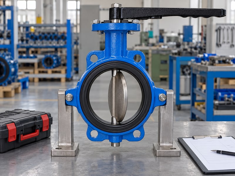
Map both sides. Use fixed labels, such as Side A and Side B, and assign pressure to each during running, shutdown, standby and maintenance isolation. A connected tank or header can change the pressure relationship when a pump stops. Ask the project engineer to establish the credible cases and ask the valve supplier which installation orientation accommodates them.
- Record the operating pressures and the maximum closed differential separately.
- Include alternate pump operation and any planned backwashing or transfer reversal.
- Keep side labels consistent across drawings, test requests and site photographs.
| System condition | Question to resolve |
|---|---|
| Valve open | Is flow permitted in this direction? |
| Valve closed | Which face carries the higher pressure? |
Key takeaway: A fixed side reference makes your review repeatable when system operation changes. Recheck any operating sequence that reverses the closed pressure differential.
3. Do offsets set butterfly valve preferred flow direction?
Offset count alone does not establish butterfly valve preferred flow direction. Concentric, double-offset and triple-offset descriptions identify geometry, but the seat arrangement and approved rating govern directional capability. Some designs use pressure-assisted sealing while others seal without depending on pressure assistance; neither behavior can be assigned to every butterfly valve.
Which seal details deserve a closer look?
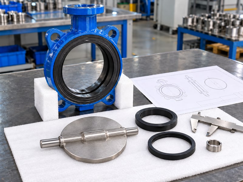
Read the seat specification. Confirm the sealing material, retainer arrangement and model-specific section drawing before using disc shape as an installation clue. You cannot infer equal forward and reverse shutoff ratings from an eccentric silhouette. RUITO's double-flanged double-offset butterfly valves require separately declared forward and reverse allowable shutoff differentials for the supplied configuration.
- Match the seat material and construction with the approved bill of materials.
- Request the direction instruction for the exact size and drawing revision.
- Keep another manufacturer's sealing description out of your own acceptance criteria.
| Design description | What still needs confirmation? |
|---|---|
| Concentric | Supplied seat's directional rating |
| Eccentric | Pressure face and reverse shutoff limit |
Key takeaway: Geometry helps you identify a design, but documentation establishes its permitted duty. Resolve the seat configuration before accepting a directional claim.
4. How is butterfly valve preferred flow direction identified?
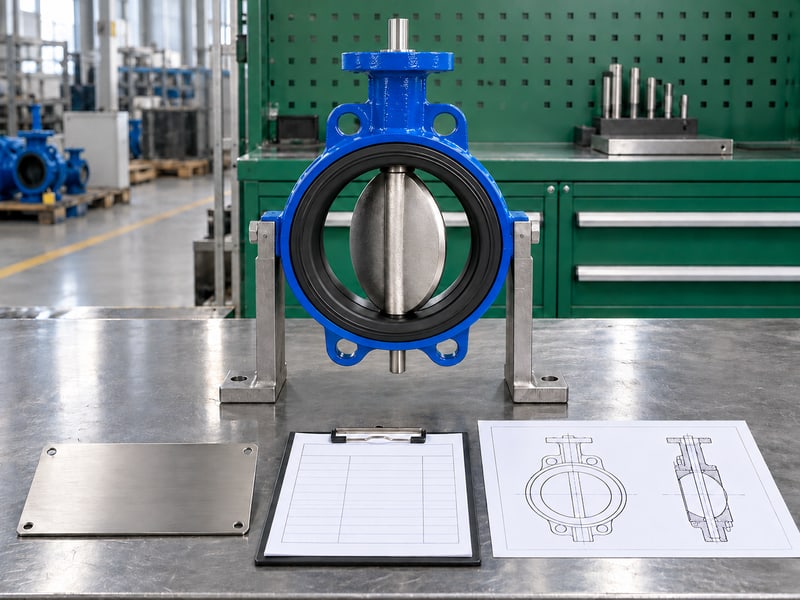
Identify butterfly valve preferred flow direction by matching the actual body marking with the valve's installation, operation and maintenance manual, or IOM. Interpret an arrow using that model's instructions; its meaning should not come from a photograph of another valve. Confirm the product identity before comparing the mark with your installation drawing. A handwheel or position indicator shows operating position and cannot identify the approved high-pressure face.
What if the mark is missing or unclear?
Resolve the mismatch before bolting up. Send the supplier clear photographs of both faces, the nameplate and any direction tag, together with the approved drawing. Ask for written confirmation that links the instruction to the supplied valve. If an arrow is missing or paperwork and markings disagree, keep the valve out of service until the supplier resolves the discrepancy.
- Verify the product ID, nominal size, pressure designation and seal configuration.
- Identify Side A and Side B on the approved installation drawing.
- Record the supplier's clarification with the receiving and installation inspection.
| Identification problem | Required action |
|---|---|
| Unclear arrow | Obtain its model-specific meaning |
| Conflicting records | Resolve identity and drawing revision |
Key takeaway: A traceable supplier response gives your installation team a usable direction instruction. Release installation only when marking and documentation agree.
5. Does suction alter butterfly valve preferred flow direction?
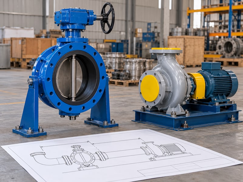
Pump suction adds a separate layout review to butterfly valve preferred flow direction. The valve's closed pressure-face requirement still comes from its supplied design, while inlet losses and disturbed approach flow affect pump operation. Disc orientation alone cannot guarantee freedom from cavitation, and a pump-discharge diagram should not be reused as a suction instruction.
What should you check with the pump supplier?
Review the complete inlet. Give the pump supplier the valve position, pipe layout, operating flow range and fluid temperature. Have the project engineer calculate available net positive suction head, or NPSH, including inlet losses, and compare it with the pump requirement and specified margin. For close connections, check the open disc's clearance against the pump nozzle and adjacent components.
- Obtain the pump manufacturer's inlet arrangement requirements for your equipment.
- Use the selected valve's flow data in the suction loss calculation.
- Check shutdown pressure reversal alongside disc clearance and installation access.
| Suction review | Confirmation needed |
|---|---|
| Hydraulic duty | Available NPSH and project margin |
| Mechanical fit | Open-disc and nozzle clearance |
Key takeaway: Treat pump inlet performance and valve shutoff direction as linked engineering checks. Resolve both before freezing a compact skid layout.
6. Do elbows affect butterfly valve preferred flow direction?
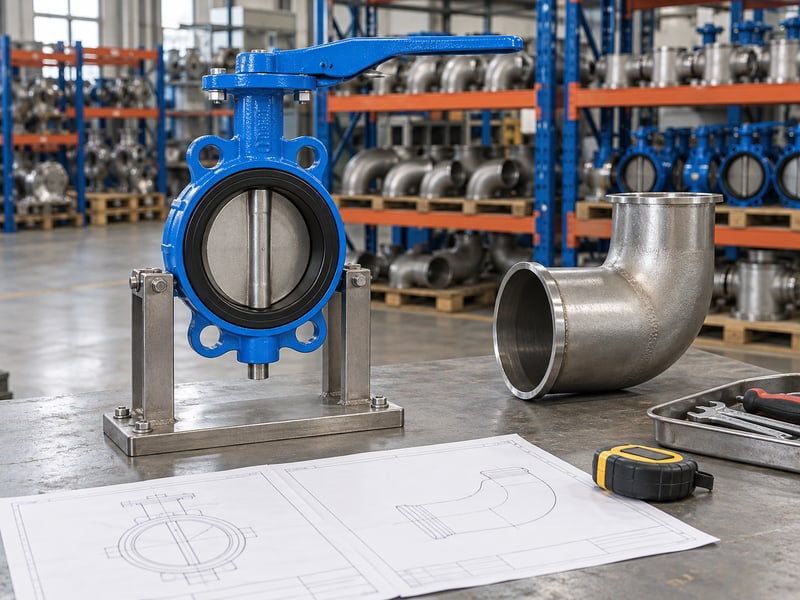
Elbows can affect approach flow and disc loading, while butterfly valve preferred flow direction remains subject to the supplied model's instructions. Nearby bends, tees and reducers can expose a partially open disc to uneven flow. Your layout review should address those disturbances together with the required closed pressure face. A change in fitting location can require a fresh review even when the valve remains the same.
How should a tight layout be reviewed?
Use the actual piping drawing. Show the supplier each nearby fitting, its orientation and distance from the valve, plus the intended operating positions. Follow the selected valve manufacturer's spacing and stem-orientation requirements. Where the available space conflicts with the IOM, ask the project engineer and supplier to review a revised arrangement or document the accepted deviation.
- Include bend planes, reducers and other valves in the layout submission.
- Identify whether the valve will isolate fully or also operate partially open.
- Keep the accepted spacing and stem orientation on the installation drawing.
| Layout feature | Review focus |
|---|---|
| Nearby fitting | Approach flow and supplier spacing rules |
| Partial opening | Dynamic loading under intended duty |
Key takeaway: A model-specific layout decision gives your installer a defensible arrangement. Escalate space constraints before fabrication makes a change expensive.
7. Can butterfly valve preferred flow direction be reversed?
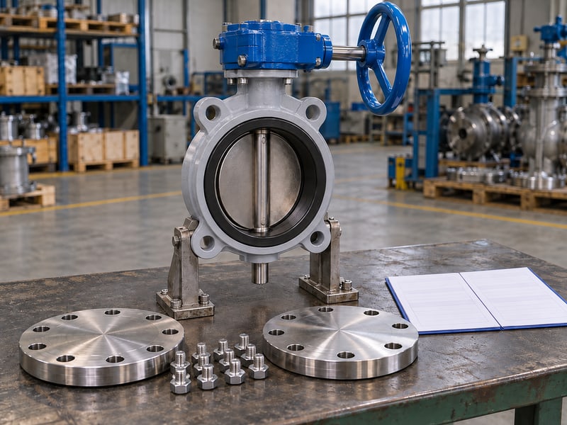
You can install against butterfly valve preferred flow direction only when the supplied valve's accepted directional limits cover that duty. Bidirectional flow when open does not establish bidirectional shutoff. Even a bidirectional shutoff description needs a declared reverse differential, temperature boundary and leakage criterion before you can approve the reversed installation.
Which reverse-duty evidence should you request?
Ask for a separate reverse declaration. Request the reverse rating and evidence under the agreed test method, such as ISO 5208:2015, for your stated conditions. A shell pressure test checks the pressure boundary; it does not establish reverse seat performance. For lined valves, review the liner, backing and shaft-seal configuration, and distinguish test pressure from allowable continuous service pressure.
- Specify reverse-duty temperature, medium and required isolation performance.
- Match reverse acceptance records with the supplied valve's product ID.
- Keep dead-end service approval separate from ordinary two-flange installation.
| Description or record | What it establishes |
|---|---|
| Open reverse flow | Permitted flow condition only |
| Reverse shutoff evidence | Defined seat performance under stated conditions |
Key takeaway: Reverse service needs its own accepted limit. Stop the approval if a forward test report is the only evidence offered for reverse isolation.
8. Does torque affect butterfly valve preferred flow direction?
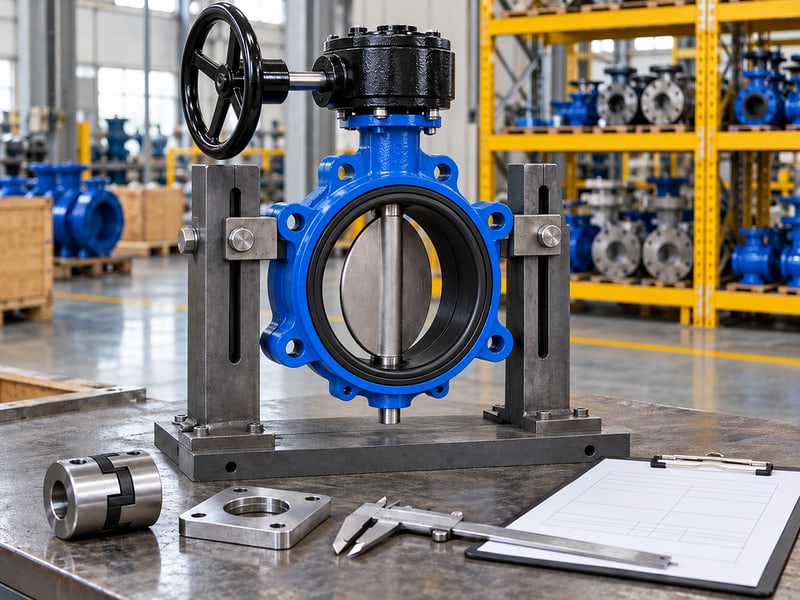
Torque affects approval of butterfly valve preferred flow direction because the actuator must operate the valve under the accepted directional duty. Seat friction, pressure loads and flow-induced torque can contribute differently through the stroke. Pressure-assisted sealing does not create a universal reduction in opening torque or justify a smaller actuator without supporting data. Include loss-of-supply operation if the actuator must move the valve to a specified failure position.
Which torque values should be compared?
Check the whole stroke. Request breakaway, running and seating torque for the selected size, seal, medium and pressure conditions. Compare these requirements with available actuator output through travel, including the minimum specified power or air supply and the required failure action. Apply the supplier's sizing method and project margin while checking shaft and drive limits alongside output.
- Review both pressure directions if the service requires reverse operation.
- Confirm the closing time and operating frequency specified by the project.
- Retain the valve torque data with the actuator selection and settings.
| Sizing input | Evidence to retain |
|---|---|
| Valve demand | Direction-specific operating torque data |
| Drive capability | Output through travel at minimum supply |
Key takeaway: Direction and actuator selection belong in the same approval record. Revisit sizing when the seal, differential pressure or operating sequence changes.
9. How is butterfly valve preferred flow direction verified?
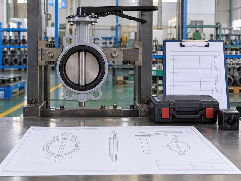
Verify butterfly valve preferred flow direction by comparing the installed valve with the approved pressure-face drawing and model-specific commissioning procedure. Check identity, orientation and mechanical clearance before applying service pressure. Perform hands-on checks only under the site's isolation, depressurization and actuator-energy control procedure, with qualified personnel responsible for the work. Retain the site result beside the supplier's configuration records so later maintenance can identify the accepted arrangement.
What belongs in the commissioning record?
Make the result traceable. Photograph the installed nameplate, direction marking and identified pipe sides, and record the IOM revision. If the contract requires a directional seat test, record the pressure face, medium, temperature, hold conditions and leakage acceptance against the product ID. An unloaded movement check confirms movement under those conditions; it cannot demonstrate rated shutoff performance.
- Confirm actual mating bore and adjacent equipment clearance against the drawing.
- Verify position indication and travel settings by the manufacturer's procedure.
- File directional acceptance evidence with the project handover documents.
| Verification stage | Record to keep |
|---|---|
| Installation | Identity and pressure-face photographs |
| Acceptance | Approved procedure and directional results |
Key takeaway: Recorded evidence lets operations verify what was approved and installed. Investigate any mismatch before accepting the valve for isolation duty.
10. Who approves butterfly valve preferred flow direction?
The valve supplier confirms model limits, and project engineers approve butterfly valve preferred flow direction for the system's actual duty. Procurement keeps those decisions tied to the order, configuration and document revisions. Installation and commissioning teams then verify conformity with the approved arrangement, giving you a clear path from selection through handover.
Which documents should you send RUITO?
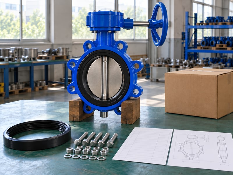
Send a complete duty. Include fluid composition, temperature, pressures on both sides, maximum forward and reverse closed differentials, and the piping layout. RUITO can review the valve configuration and provide applicable data sheets, installation drawings, torque data, IOM and contractual inspection records. Keep any unresolved system transient or pump inlet question with the responsible project engineer.
- Provide the valve size, connection, mating flange details and available space.
- State the leakage requirement and any contractual witness or test obligations.
- Identify the project engineer responsible for layout and operating-case approval.
- Retain the accepted seal, drive and drawing revisions on repeat orders.
| Responsibility | Required decision |
|---|---|
| Supplier | Confirm supplied configuration and limits |
| Project team | Accept duty, layout and installation |
Key takeaway: Close the pressure-face, reverse-rating, layout and actuator questions before ordering. Contact us today with your data sheet and installation drawing for a documented RUITO review. RUITO bases its recommendation on the configuration and evidence required for your stated duty.
FAQ
Q1: Can I install a butterfly valve in either direction?
Only if the supplied model permits your duty in that orientation. Check its IOM and forward and reverse shutoff limits, including temperature and leakage requirements.
Q2: How do I know if the arrow means normal flow or pressure direction?
Read the model-specific marking explanation. Match the arrow with the supplied IOM and drawing, then ask the supplier to resolve any ambiguity before installation.
Q3: Can I assume a double-offset valve seals at full pressure both ways?
No. Offset count does not establish equal directional ratings. Ask for the supplied valve's separate forward and reverse allowable shutoff differentials and applicable acceptance evidence.
Q4: What's the best orientation for a valve near pump suction?
Use the arrangement accepted for that pump and valve. Review inlet losses, available NPSH, manufacturer layout instructions, disc clearance and closed pressure reversal together.
Q5: Can I correct a direction problem by changing actuator settings?
Only if the supplier confirms a settings issue under the approved procedure. Travel or torque changes cannot establish a missing reverse shutoff rating and may damage components.