
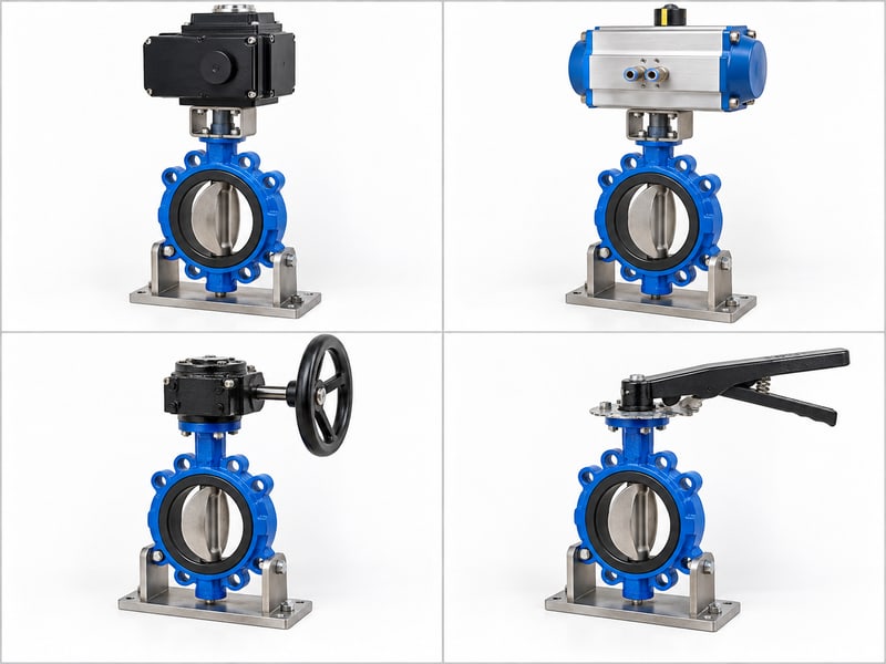
Fix motor butterfly valve mistakes by matching the valve's fluid and pressure limits with the drive's torque, duty, controls, and failure behavior. A powered assembly can fit the pipe yet stall during isolation or stop in the wrong position. Check the complete package before issuing a purchase order.
1. What is a motor butterfly valve?
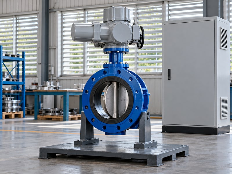
A motor butterfly valve combines a butterfly valve with an electric drive that rotates its disc through the required travel. The package includes a mechanical connection and controls appropriate to its duty. Selection needs both valve and electrical information.
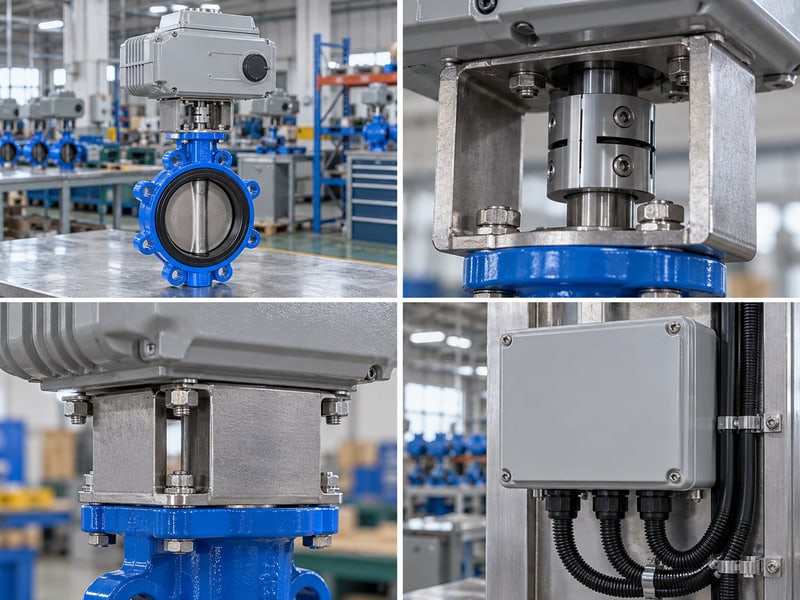
Which components belong in the package?
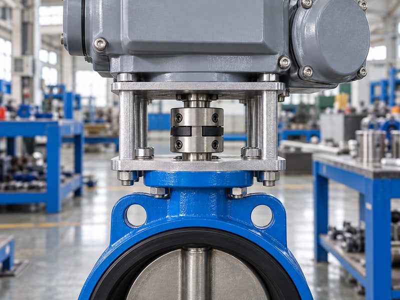
Identify the valve body, disc, seat, shaft, drive, coupling, bracket, and position controls. Depending on the drive, reduction gearing may sit inside the actuator or form a separate assembly. Procurement should define who supplies and verifies each interface rather than ordering unrelated components by nominal size.
- Match the valve and drive identification.
- Confirm coupling dimensions and attachment details.
- Request the assembled dimensions and connection diagram.
Buy against the complete assembly specification. A matching mounting flange does not establish torque capacity, correct shaft engagement, or suitable travel. The assembled drawing should show how the drive transfers torque without loading an unintended component.
How should you describe the function?
State whether the valve provides remote isolation, automatic sequencing, or continuous positioning. Those functions create different drive and control requirements even when the valve bodies match. Key takeaway: define the complete package and its task before comparing quotations.
| Package element | Verify |
|---|---|
| Valve | Process and shutoff limits |
| Drive | Torque and duty |
| Interface | Coupling and controls |
Add the operating function to the enquiry heading.
2. How does a motor butterfly valve complete a cycle?
A motor butterfly valve completes a cycle by receiving a command, driving the shaft, reaching its specified position, and reporting the result where feedback is fitted. The stopping method depends on the drive design. Command acceptance alone does not prove disc movement or successful shutoff.
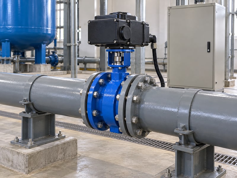
What happens between command and stop?
The motor turns through gearing and the coupling to move the disc. Controls may use configured position limits, torque limits, or other model-specific logic. Check the assembly instructions so stopping settings protect the valve and correspond to its approved travel.
- Identify open, close, and stop commands.
- Verify the permitted local and remote modes.
- Define how travel completion and faults are reported.
Verify movement after setting the controls. A loose or incorrectly indexed coupling can leave an indicator showing an apparent end position while the disc differs. Check mechanical indexing through the approved procedure before accepting electrical feedback as position evidence.
What should a functional check demonstrate?
Confirm commanded direction, complete travel, position indication, and the specified stopping behavior. Test under the agreed conditions with personnel clear of moving parts and the valve bore. Key takeaway: acceptance follows a verified command-to-disc sequence, including the stop and feedback response.
| Cycle stage | Check |
|---|---|
| Command | Correct direction and mode |
| Movement | Verified disc travel |
| Completion | Stop and feedback agree |
Retain the functional check with the valve tag.
3. Which applications fit a motor butterfly valve?
A motor butterfly valve fits an application when the selected valve handles the medium and operating conditions while its electric drive meets the required function. Remote operation can suit accessible utility power and planned control sequences. The motor itself establishes no fluid-service approval.
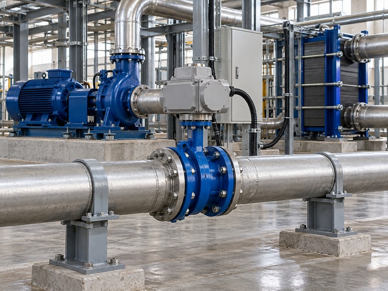
Where does electric operation help?
Water and cooling systems may need remote branch isolation, pump sequencing, or equipment interlocks. For RUITO's HVAC and district energy applications, identify whether the valve isolates a circuit or regulates flow. Do not assume an on/off package can perform continuous modulation because it accepts electrical commands.
- State the normal and upset operating tasks.
- Describe the medium, additives, and solids.
- Identify power availability and control-system requirements.
Select the service before selecting automation. A motor can operate an unsuitable seat as readily as a suitable one. Fire protection, fuel gas, hygienic processing, and hazardous locations each require their own applicable model and system review.
What needs a separate application review?
Review abrasive solids, long fibers, hot fluids, corrosive chemicals, and unstable two-phase conditions before choosing a valve. A utility-water configuration should not inherit another product's process limits. Key takeaway: electric actuation solves an operating task after the valve's service suitability is established.
| Application question | Needed input |
|---|---|
| Fluid suitability | Composition and phase |
| Operating task | Isolation or modulation |
| Site suitability | Power and environment |
Write the process duty beside the control function.
4. What limits a motor butterfly valve's pressure rating?
A motor butterfly valve's pressure rating comes from the configured valve and connections at the operating temperature. The electric motor does not increase that rating. Maximum differential across the closed disc and permitted pressure direction require separate confirmation for shutoff and torque selection.
Which ratings must stay together?
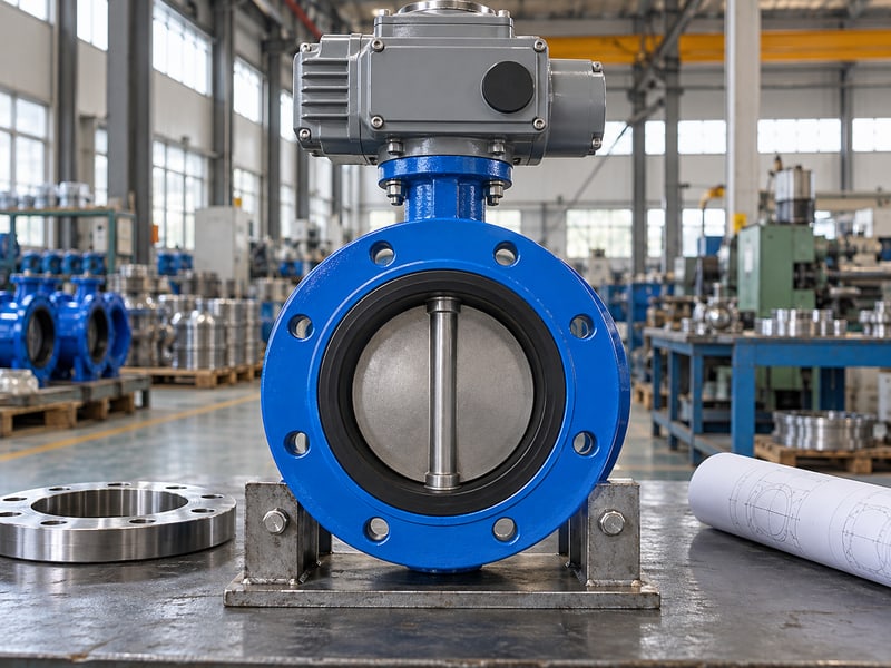
Check nominal pressure class, working pressure-temperature limits, and directional shutoff differential on the same valve. RUITO's flanged butterfly valve options include concentric DN50–600 and double-eccentric DN350–3000 configurations at PN10/16. Their sizes and directional limits remain configuration-specific despite sharing an electric operating option.
- Provide normal, maximum, and transient line pressure.
- State forward and reverse closed differentials.
- Confirm companion flange and connection ratings.
Keep proof pressure separate from working limits. A factory pressure report records a test condition and acceptance result. It does not authorize routine service at that test pressure or establish identical reverse-pressure sealing capacity.
How should a replacement be compared?
Compare the complete pressure-temperature envelope and closed-differential limits with the existing process specification. Matching pipe bore, flange holes, or actuator voltage cannot establish pressure equivalence. Key takeaway: approve working limits and directional shutoff before sizing the powered drive.
| Rating | What it describes |
|---|---|
| Working pressure-temperature | Service envelope |
| Closed differential | Disc and seat condition |
| Proof test pressure | Inspection condition |
Attach the model's working and shutoff data to the order.
5. Which materials suit a motor butterfly valve?
A motor butterfly valve needs compatible materials throughout its wetted assembly, including the disc, seat, shaft seals, and lining where fitted. Selection depends on actual fluid composition and temperature. Actuation does not make a water-service seat suitable for oil, steam, or arbitrary chemicals.
What must the fluid description include?
List concentration, additives, contaminants, cleaning agents, and possible changes during operation. For RUITO's approved water/glycol configurations, the stated range includes inhibited ethylene glycol at 0–40% by volume, 5–60°C, and no more than 10 barg. The selected size, materials, and working curve still govern.
- Identify every wetted material in the offered configuration.
- Verify elastomer compatibility with the actual medium.
- Review temperature and pressure as a combined condition.
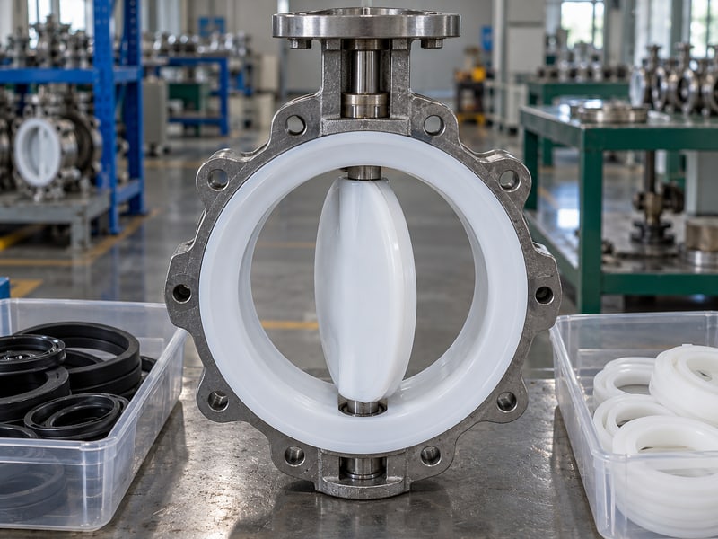
Check the whole sealing arrangement. RUITO's PTFE lined butterfly valve options require coordinated review of lining, backing, and shaft seals. A PTFE material name alone does not approve all acids, concentrations, cleaning fluids, or vacuum conditions.
How do you avoid material substitution errors?
Require the approved material list to accompany the dimensional drawing and operating limits. EPDM water-service and dedicated oil-service configurations need separate review; neither should be substituted through a generic seat description. Key takeaway: retain the complete wetted configuration throughout purchasing and repeat orders.
| Medium detail | Selection consequence |
|---|---|
| Oil and additives | Dedicated seal review |
| Glycol concentration | Fluid and seal verification |
| Chemical and cleaning fluid | Complete lining/seal review |
Send the actual fluid composition with your request for quotation.
6. How much torque does a motor butterfly valve need?
A motor butterfly valve needs sufficient drive output throughout opening, running, and closing at the specified worst operating conditions. Valve diameter or motor wattage alone cannot determine that requirement. Compare the valve's required torque with available assembly output and the permitted mechanical limits.
Which conditions change required torque?
Use the manufacturer's data for the selected size, seat, temperature, pressure direction, and closed differential. Include packing friction and relevant dynamic flow loads. A drained downstream line or reverse pressure can create a demanding condition absent from normal circulation.
- Obtain breakaway, running, and seating torque requirements.
- Confirm output at the specified supply and duty conditions.
- Apply the sizing margin required by the project and supplier.
Compare torque at the valve shaft. A motor's electrical power does not state usable geared output without speed, gearing, losses, and operating limits. Couplings, brackets, and the valve shaft also need sufficient capacity for the approved assembly and protection settings.
Can a larger drive solve every problem?
No; excess available torque can damage a valve if protective settings or component limits are wrong. A stalled assembly needs diagnosis of pressure, obstruction, installation, and controls before force is increased. Key takeaway: sufficient controlled shaft torque must coexist with the valve's mechanical limits.
| Torque condition | Verify |
|---|---|
| Breakaway | Required initial movement |
| Running | Output across travel |
| Seating | Approved closing limit |
Request the torque selection record for the assembled package.
7. What duty and speed suit a motor butterfly valve?
A motor butterfly valve needs a drive rated for its actual cycle pattern and a travel time acceptable to the piping system. Duty limits depend on the supplied model and ambient conditions. Faster closure can increase hydraulic transient loads rather than improve the installation.
How should you describe cycling duty?
Provide starts per hour, running time, rest periods, reversals, and expected positioning activity. Continuous positioning can involve repeated short movements that differ from occasional full strokes. Ask for the applicable duty declaration and cycle diagram instead of applying one universal electric-actuator percentage.
- State the busiest credible operating period.
- Include ambient temperature and installed heat exposure.
- Define whether the controls may issue repeated small corrections.
Choose travel time from the system requirement. Opening and closing times should support the process while respecting surge analysis and equipment sequencing. Pump protection or chemical isolation may need a specific response, but that response must be engineered for the actual system.
What should you ask about overload behavior?
Confirm what happens if thermal protection, torque protection, or a duty limit interrupts movement. Define the resulting alarm and the site's recovery procedure. Key takeaway: the rated cycle pattern, acceptable travel time, and overload response belong in one operating specification.
| Duty input | Reason |
|---|---|
| Starts and reversals | Motor/control loading |
| Run and rest times | Rated cycle verification |
| Travel time | Process and surge review |
Submit the intended cycle diagram with the drive enquiry.
8. How does a motor butterfly valve report its position?
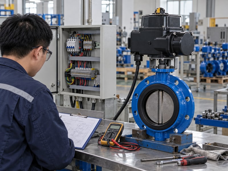
A motor butterfly valve reports position through the feedback devices and signals specified for its assembly. End switches can indicate configured end states, while a position transmitter can report intermediate travel where fitted. Neither signal automatically confirms tight sealing or measured flow.
Which signals should controls staff define?
Separate command, travel feedback, local/remote status, and fault indication in the signal schedule. An analog position demand and an analog position return have different functions despite using similar signal formats. Check supply, wiring, protocol, and signal-loss behavior against the connection diagram.
- Identify open and closed status requirements.
- Define intermediate position feedback if needed.
- List faults that the control system must receive.
Separate position evidence from shutoff evidence. A switch can report that its configured mechanism reached an end position. Seat leakage acceptance requires the approved valve test conditions, while flow control needs suitable valve characteristics and process information.
How should commissioning verify feedback?
Check each signal against observed travel through a safe, approved procedure. Include local override, remote commands, and configured fault conditions in the test plan. Key takeaway: useful feedback tells operators what the assembly has verified, with sealing and flow checks defined separately.
| Signal | Meaning to verify |
|---|---|
| End switch | Configured end state |
| Position return | Intermediate travel |
| Fault alarm | Defined abnormal condition |
Approve the command and feedback schedule before wiring begins.
9. What happens if a motor butterfly valve loses power?
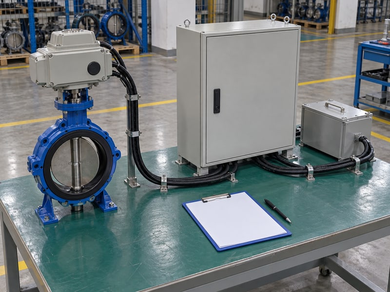
A motor butterfly valve follows its specified power-loss behavior; it does not automatically fail closed. A conventional drive may stop, while a suitable stored-energy arrangement may move toward a defined position. Confirm the exact assembly's behavior under the required failure conditions.
Which failure conditions differ?
Loss of supply, loss of command signal, control faults, and mechanical stalling can produce different outcomes. A backup battery, spring, or other stored-energy system needs its own rating, readiness checks, and maintenance instructions. Do not infer reliable fail action from the presence of an electric motor.
- Define the required position for each specified failure.
- State available backup energy where applicable.
- Identify alarms and permitted manual recovery.
Specify the failure response explicitly. A process review should establish whether stopping, opening, or closing is required for the defined event. Hazardous-area approval and functional-safety claims require their own evidence and cannot be inferred from a fail-position label.
What should be demonstrated before service?
Include approved power-loss and signal-loss checks in the commissioning plan where applicable. Follow the model instructions for restoring power and control after an interrupted stroke. Key takeaway: accept documented and verified failure behavior rather than assuming every powered valve moves to a safe position.
| Event | Define |
|---|---|
| Supply loss | Stop or stored-energy action |
| Signal loss | Configured control response |
| Mechanical stall | Protection and alarm |
Write the required failure matrix into the control specification.
10. What should a motor butterfly valve RFQ include?
A motor butterfly valve RFQ should define the process, valve interface, electrical supply, duty, controls, and acceptance documents for the complete assembly. These inputs allow a technically comparable proposal. Price comparisons become unreliable when quotations leave seat materials, torque conditions, or failure behavior unspecified.
What should a motor butterfly valve enquiry include?
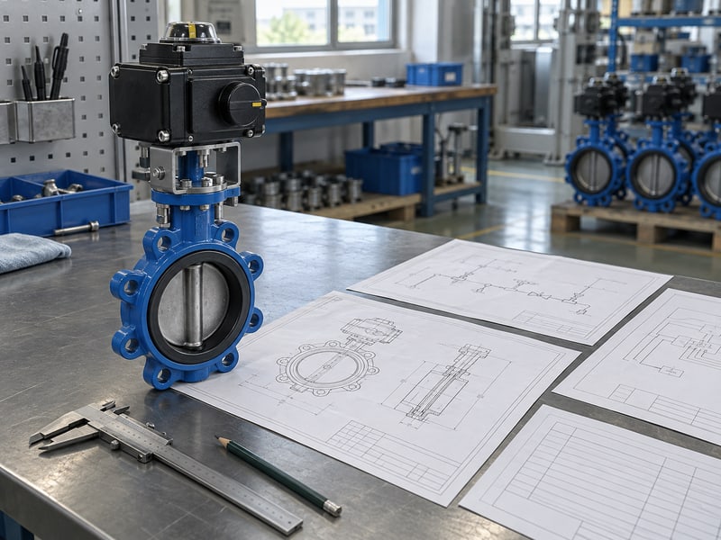
Provide fluid composition, size, working temperature and pressure, directional closed differential, and flange details. Add power supply, cycle pattern, travel time, command and feedback schedule, and required failure response. Attach the process and control requirements together. Retain access, support, and maintenance information without making mounting position the whole selection decision.
- Request working limits and the torque selection record.
- Obtain assembly, connection, and installation drawings.
- Define inspection, commissioning, and maintenance requirements.
What should the final proposal commit to?
Ask for the offered configuration, stated deviations, model manuals, acceptance criteria, and spare-parts information. RUITO can review your process inputs and assembly requirements before configuration approval. Key takeaway: a complete proposal connects material and pressure limits with verified drive duty and controls; contact us today with your datasheet and cycle diagram.
| RFQ group | Required information |
|---|---|
| Process | Medium, temperature, pressure |
| Mechanics | Interfaces and torque |
| Electrical/control | Supply, duty, signals, failures |
Close deviations before approving the assembly for purchase.
Frequently asked questions
Q1: Can I select a drive from valve diameter alone?
No. Use model-specific torque, closed differential, temperature, duty, and mechanical limits.
Q2: What's the best closing speed?
Use the system's approved travel time. Fast closure can increase pressure surges or disrupt sequencing.
Q3: Can an electric valve always fail closed?
No. Its specified drive and stored-energy arrangement determine behavior after supply loss.
Q4: How do I know a closed signal proves isolation?
It does not prove seat tightness. Verify indication and shutoff through their separate approved checks.
Q5: Does electric operation mean maintenance-free service?
No. Follow the valve and drive manuals for inspections, servicing, exercising, and any backup-energy checks.