
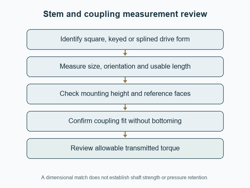
Butterfly valve stem size includes the relevant shaft diameter or drive form, its usable engagement length and its position relative to the mounting face. Compare "butterfly valve stem sizes" using a dimensioned interface drawing. Two stems described as '20 mm' can require different couplings if one is square, another is keyed, or their available engagement differs.
1. What do butterfly valve stem sizes describe?
Stem sizes can describe different features of the same shaft, so name the feature before recording a number. A round bearing journal, sealing diameter, square drive end and keyed coupling section serve different purposes. Their dimensions are not interchangeable. For actuator replacement, the exposed drive interface and mounting references usually govern the coupling review, while internal shaft features remain part of the controlled valve design and maintenance procedure.
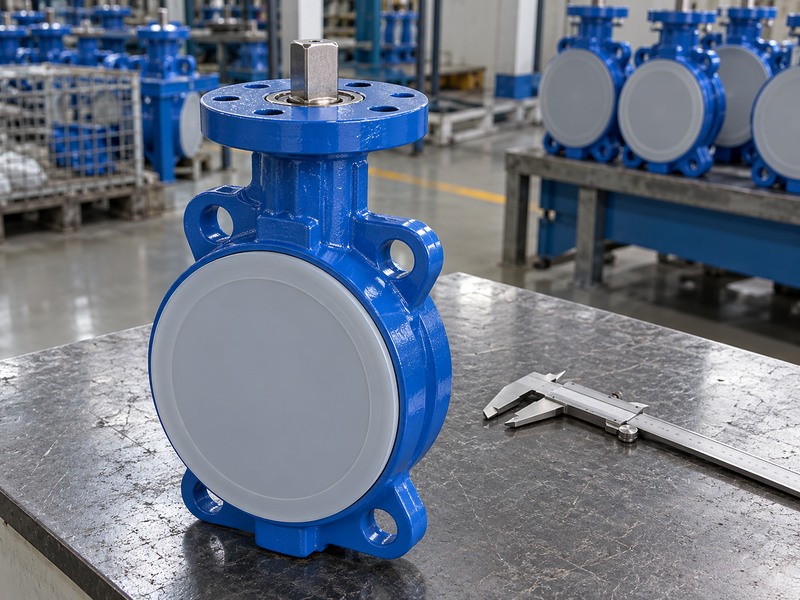
Which stem feature does the drawing identify?
Use a sketch that marks each measured surface and its reference position. Record whether the stem is one piece or part of a multi-component arrangement only when the drawing confirms it; external appearance may not reveal the internal construction. Do not assume the upper drive size establishes the lower journal or disc connection. When a quotation lists a shaft diameter without a dimensional key, ask which section it describes before using that value to order a coupling or spare.
- Label the exact shaft feature being measured.
- Separate external drive dimensions from internal design features.
- Retain the drawing revision and measurement references.
| Stem feature | Common dimension | Purpose to review |
|---|---|---|
| Bearing or sealing section | Diameter and finish requirements | Internal support or sealing |
| Upper drive | Square, keyed or other form | Torque transfer to the operator |
| Exposed length | Reference height and usable contact | Coupling engagement |
2. How do you identify the drive form?
Identify whether the operator connects through a square, double-D, keyed round, splined or another specified drive form. Record the orientation and any locating feature as well as the apparent size. A round hole cannot substitute for a square socket merely because one measured width matches. The selected coupling must transmit the required torque through the intended contact surfaces without excessive play, inadequate engagement or unintended shaft loading.
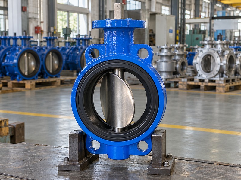
Which features should the survey include?
Photograph the drive end from above and from the side under the approved inspection procedure, then add dimensions to a simple sketch. Keep the orientation relative to the valve's travel references visible; a coupling that fits at one orientation may incorrectly index the operator. For a replacement drive, compare the new coupling drawing with the actual stem and mounting arrangement. Avoid identifying a spline or proprietary form from a single photograph when its detailed geometry remains unconfirmed.
- Record form and orientation together.
- Identify the surfaces intended to transmit torque.
- Mark proprietary or inaccessible features as unconfirmed.
| Drive form | Details to record | Insufficient measurement |
|---|---|---|
| Square or double-D | Defined widths, orientation and length | One arbitrary outside reading |
| Keyed round | Diameter, key and keyway geometry | Diameter alone |
| Spline or special form | Controlled profile specification | Approximate visual resemblance |
3. How do across-flats and across-corners sizes differ?
Across-flats measures the distance between opposite flat faces of a square drive, while across-corners measures its diagonal. They are different values. For an ideal 20 mm square used only as a geometry example, the diagonal is about 28.3 mm. Reporting that diagonal as a '28 mm stem' would describe the wrong interface. Follow the coupling drawing's dimension convention and inspect the condition of the flats before interpreting a field reading.
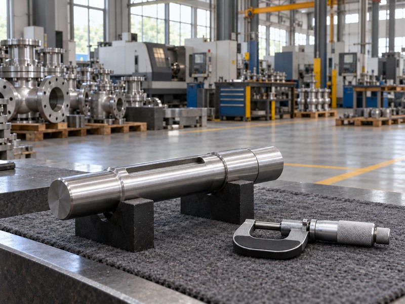
How should you measure a worn square end?
Use suitable measuring surfaces and record wear, rounded corners or burrs that can affect the result. Take readings on the specified contact area rather than a damaged tip or chamfer. For a wafer butterfly valve with a retained operator, compare the measured flats and usable length with both the valve and coupling drawings. A new socket that slides onto a worn stem does not establish an acceptable torque fit; the responsible reviewer must assess contact, clearance and the remaining condition.
- State across-flats or across-corners explicitly.
- Avoid measuring chamfers as full drive surfaces.
- Record wear instead of rounding the value to a convenient nominal size.
| Illustrative square | Measurement | Meaning |
|---|---|---|
| 20 mm ideal square | 20 mm across flats | Distance between opposite faces |
| Same ideal square | About 28.3 mm across corners | Diagonal, not the socket's across-flats callout |
| Used drive end | Measured values and condition | Needs drawing and wear review |
4. Which dimensions identify keyed or splined stems?
A keyed round stem needs its shaft diameter, keyway width and depth, key details and usable engagement length. A splined stem needs the specified profile information, such as the controlled tooth geometry and fit, rather than only its largest diameter. These features determine how the coupling locates and transfers torque. Use the original interface drawing or a supplier-confirmed specification when the form cannot be identified reliably from ordinary field measurements.
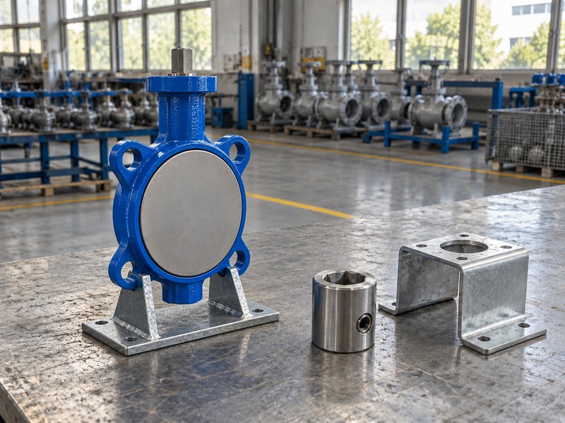
Can a replacement key be chosen by width alone?
Key height, length, end form, material and its relationship to both keyways remain part of the connection. An apparently suitable loose key can bottom in the coupling or fail to contact as intended. Record whether the original key is captive, removable or otherwise retained according to the drawing. Do not alter a keyway, file a spline or force an oversized component to obtain assembly fit. Such changes affect contact and load transfer and need an accepted engineering disposition.
- Specify the complete keyed or splined interface.
- Check the coupling-side geometry as well as the stem.
- Control repairs or modifications to torque-transmitting features.
| Interface | Required information | Risk of a partial callout |
|---|---|---|
| Keyed shaft | Diameter, keyway and key dimensions | Incorrect contact or bottoming |
| Coupling keyway | Matching form and clearance | False fit with inadequate torque transfer |
| Spline | Controlled profile and fit | A matching outside diameter can still be incompatible |
5. How do you measure usable drive engagement?
Measure usable engagement along the stem section that the coupling is designed to contact, excluding chamfers, reliefs and unsupported assumptions about hidden length. Record the height from the defined mounting face to the stem end and any shoulder or stop that controls assembly. The total exposed shaft length may exceed the usable drive length. A coupling can therefore look fully installed while contacting only part of the intended torque-transmitting surface.
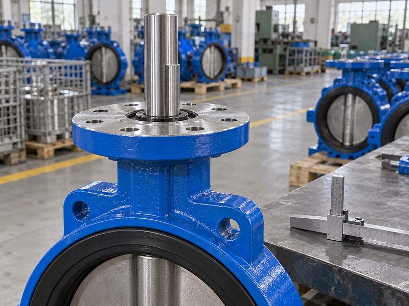
Which reference heights must the drawings share?
Use the valve mounting face as the agreed reference and show the bracket and coupling dimensions relative to it. ISO 5211 addresses specified part-turn attachment interfaces; the complete assembly still needs its actual support and coupling review. Check that the coupling neither bottoms on the stem nor imposes unwanted axial loading when the bracket is tightened. Keep the required contact length and permitted clearances explicit rather than deriving them from a general mounting designation.
- Distinguish exposed length from usable engagement.
- Use a common mounting reference face.
- Confirm contact and bottom clearance after assembly.
| Length or height | Reference | Why it is needed |
|---|---|---|
| Stem-end height | Accepted mounting face | Locates the drive end |
| Usable drive length | Full intended contact surfaces | Establishes available engagement |
| Coupling position | Bracket and operator assembly | Prevents bottoming or inadequate contact |
6. How do you confirm coupling fit without forcing it?
Confirm coupling fit from the approved dimensions, tolerances and assembly procedure, then inspect the actual parts and their condition. A clearance that allows assembly may still be excessive for the intended torque transfer, while a tight fit can arise from burrs, coatings or misalignment. Do not use bracket bolts to pull an incompatible coupling onto the shaft. Establish the cause before applying force that can damage the drive surfaces or load the valve stem axially.
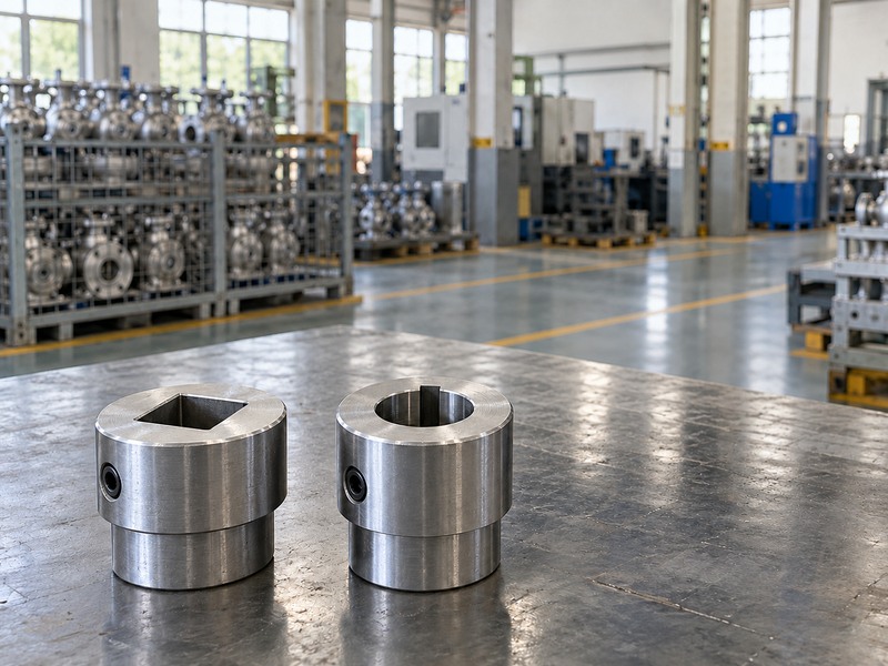
Which assembly checks should be documented?
Check orientation, usable contact, clearance at shoulders and the final bracket position. Confirm that tightening the mounting fasteners does not change the valve's permitted movement or introduce unwanted loads. For a lug butterfly valve package, keep the selected coupling and bracket revisions linked to the valve and operator. If an adaptor is proposed, assess the complete torque path and envelope rather than accepting its matching end dimensions as proof of adequate strength or alignment.
- Inspect damage and cleanliness before trial assembly.
- Use the specified fit and alignment criteria.
- Review adaptors as torque-transmitting components.
| Fit check | Observation | Action if unresolved |
|---|---|---|
| Contact and clearance | Matches the accepted drawing | Confirm tolerance or wear disposition |
| Orientation | Agrees with valve travel references | Correct indexing before operation |
| Bracket assembly | No forced fit or unintended loading | Review the complete mounting arrangement |
7. Can stem dimensions establish torque capacity?
Stem dimensions alone cannot establish allowable transmitted torque. Material, heat treatment, cross-section changes, keyways, disc attachment, bearings and load combinations can govern the design. A larger visible drive end does not automatically permit a stronger actuator. Obtain the valve manufacturer's allowable torque and compare it with the proposed drive's maximum possible output, including the accepted supply range, protection settings and operating cases.
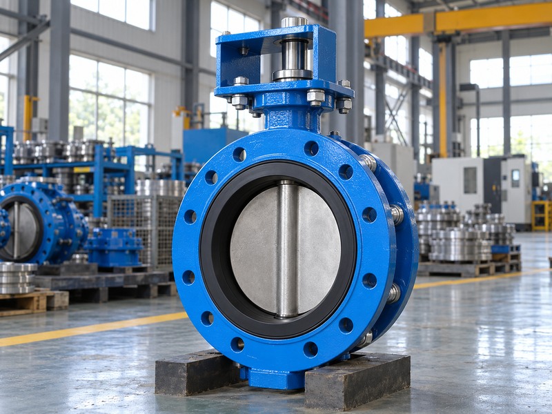
What should an actuator replacement review include?
Keep required valve operating torque separate from allowable shaft torque. The first establishes minimum drive demand; the second limits the load that may be transmitted. For a flanged butterfly valve assembly, include coupling, bracket and stop limits alongside the shaft. A new operator can fit the same square while delivering a much larger peak load. Review its maximum output and stopping method before accepting the replacement, and correct any physical disc interference instead of using the larger drive to overcome it.
- Request allowable torque from the valve supplier.
- Compare maximum output as well as normal demand.
- Review every component in the transmitted torque path.
| Quantity | Purpose | Cannot be inferred from |
|---|---|---|
| Required valve torque | Minimum operating demand | Stem size alone |
| Allowable shaft torque | Mechanical load limit | A larger exposed square |
| Drive maximum output | Potential transmitted load | Its nominal model size alone |
8. How should you inspect a used stem or spare?
Inspect identity, geometry and condition under the manufacturer's approved maintenance procedure. Record wear, corrosion, cracks, damaged keys, rounded flats and evidence of movement at the connection. A used stem may no longer match its original dimensions. Internal shaft removal also involves sealing, retention and assembly features that an external measurement survey does not qualify, so keep replacement decisions tied to the controlled valve design and accepted repair scope.
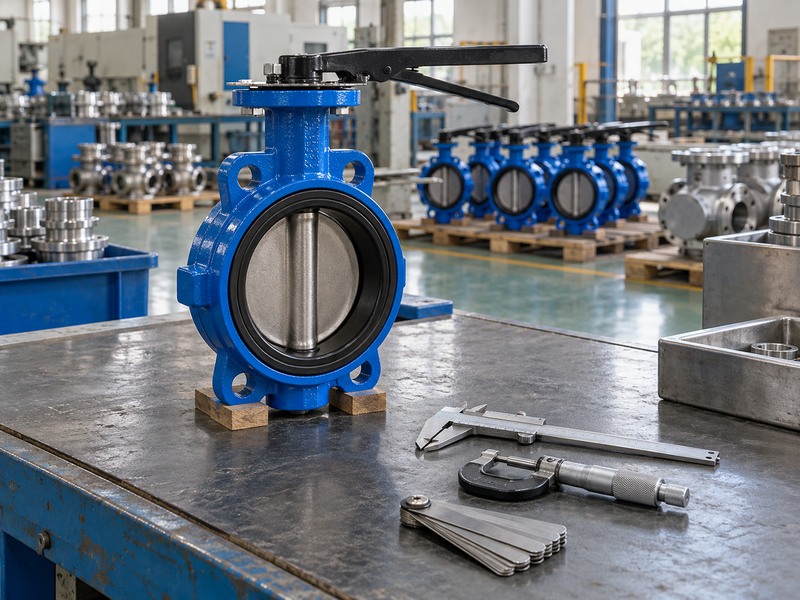
Which evidence makes a spare reviewable?
Use product identification, drawing revision, material specification and the required inspection records for the proposed spare. Appearance and one matching diameter do not establish compatibility. If an original part is unavailable, a replacement needs the responsible engineering assessment of geometry, material, strength, sealing and retention features. Photograph the condition before repair and keep the accepted disposition. Do not treat a new upper coupling as a remedy for damage or wear deeper in the stem and disc connection.
- Record identity and condition before changing parts.
- Separate external coupling work from internal shaft replacement.
- Retain approved repair and spare specifications.
| Evidence | What it supports | Limit |
|---|---|---|
| Field measurements | Geometry and visible condition | May reflect wear or damage |
| Controlled drawing | Original features and references | Must match the valve revision |
| Spare material and inspection | Proposed replacement identity | Needs complete design acceptance |
9. What should a stem-size enquiry contain?
Send a dimensioned sketch, clear photographs, valve identification and the intended replacement scope. Label every diameter, across-flats value, usable length and mounting reference. Include the operator or coupling drawing when it will be retained, and state the required operating torque and known mechanical limits. Mark hidden or uncertain features explicitly so the supplier can identify what must be confirmed before a replacement coupling, drive or shaft is accepted.
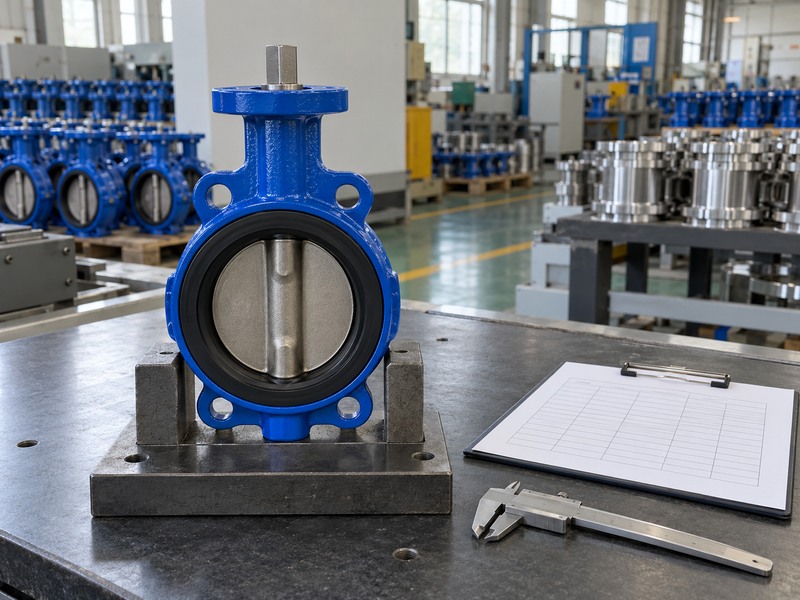
How do you close the interface review?
Ask for a marked assembly drawing that identifies the accepted drive form, engagement, tolerances, orientation and required clearances. For RUITO enquiries, contact us with the survey and valve duty so engineering can review both dimensional fit and transmitted loads. Keep the accepted response with the order and maintenance record. If a proposed substitute changes a keyway, shaft material, coupling length or mounting height, reopen the affected checks before it reaches the installation team.
- Label measurements with their feature and units.
- State what is retained and what is replaced.
- Resolve geometry and load questions before release.
| Enquiry element | Include | Decision supported |
|---|---|---|
| Identification | Valve and drawing revision | Correct interface family |
| Dimensioned survey | Form, widths, lengths and references | Physical fit review |
| Duty and scope | Torque limits and retained components | Accepted replacement assembly |
10. What questions arise when measuring valve stems?
Q1. Can I choose a coupling from stem diameter alone?
No. Record the drive form, tolerances, orientation, usable engagement and mounting reference. A square, keyed or splined interface needs its own complete specification.
Q2. How do I know whether a square measurement is across flats?
Measure between the intended opposite flat faces and label it explicitly. The corner-to-corner diagonal is larger. Avoid using chamfers or worn corners as the reference for a nominal drive size.
Q3. Can a larger actuator be fitted to the same stem?
Only after checking required torque, maximum possible output and the allowable shaft, coupling and bracket limits. Dimensional fit does not establish mechanical capacity.
Q4. What's the best way to identify an unknown spline?
Use the original drawing or a supplier-confirmed profile specification with suitable inspection. Outside diameter and a photograph leave tooth form, fit and engagement unresolved.
Q5. Can I copy a worn stem to make a spare?
A worn sample needs comparison with the controlled design and an accepted replacement specification. Geometry, material, strength, sealing and retention requirements remain part of the shaft review.