
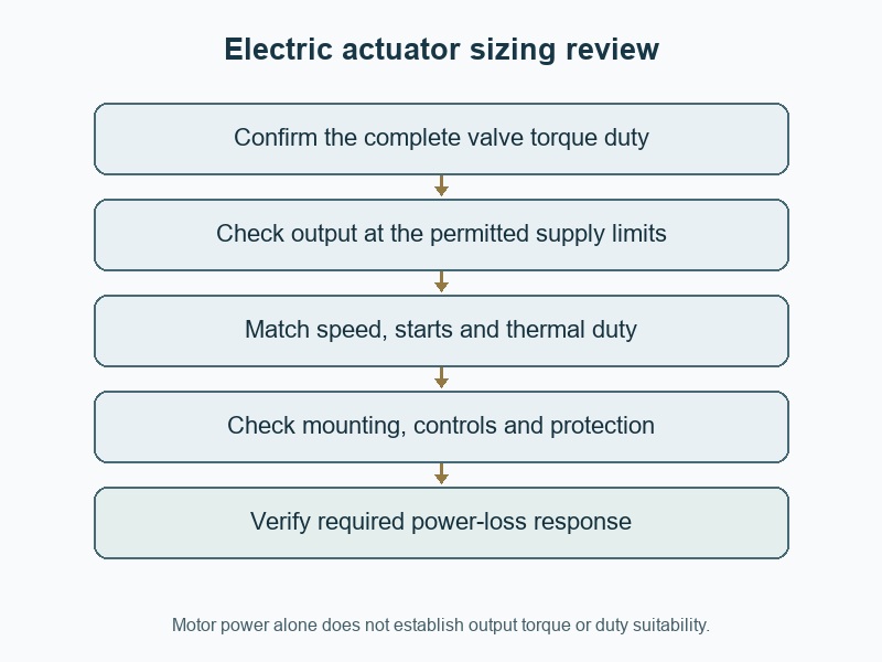
Size an electric butterfly valve actuator from the valve torque duty, available electrical supply, required speed and operating frequency. For "how to size electric butterfly valve actuators", confirm those inputs before comparing motor power or housing size. A drive can complete one unloaded stroke while still being unsuitable for repeated modulation or the maximum differential-pressure case.
1. How to size electric butterfly valve actuators?
Start with the exact valve's torque requirements throughout travel and the operating cases the electric drive must complete. Include unseating, running and seating conditions at the specified temperature, fluid and differential pressure. Confirm the required direction, timing and loss-event response. Then obtain the actuator's guaranteed output under its permitted electrical supply and duty conditions, rather than accepting a catalogue torque without the circumstances that qualify it.
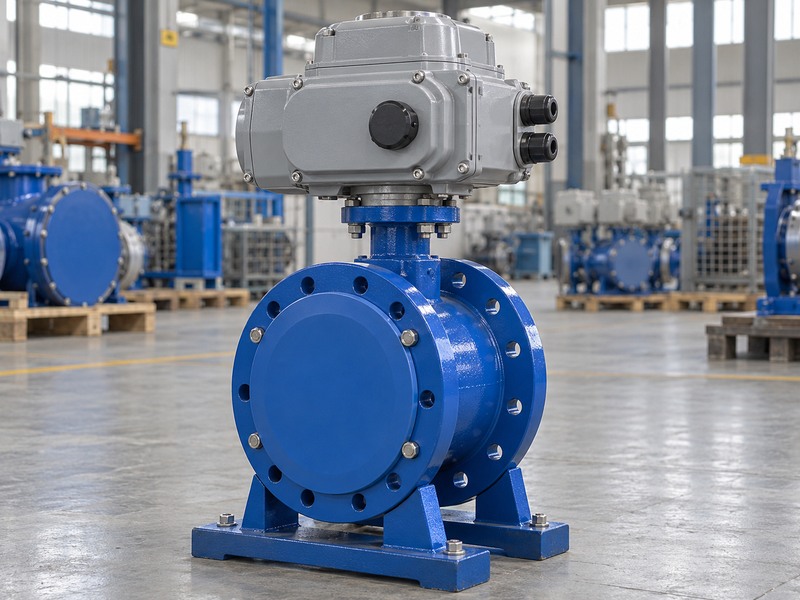
Which documents should precede the model selection?
Request the valve torque basis, allowable shaft torque, mounting drawing and the proposed operator data sheet. Record whether torque allowances are already included so the same margin is not added twice. For a wafer butterfly valve, confirm that the torque data applies to the selected seat and installed sealing arrangement. A valve that binds because of flange compression, disc interference or misalignment needs mechanical correction; choosing a larger motor can transfer the problem into the shaft or coupling.
- Obtain required torque and mechanical limits separately.
- Define the full operating and loss-event cases.
- Confirm the supply and duty basis of the proposed output.
| Selection input | Required detail | Why it is separate |
|---|---|---|
| Valve torque | Demand throughout the specified stroke | Determines minimum output |
| Mechanical limits | Shaft, coupling and mounting capacity | Limits maximum transmitted load |
| Electrical duty | Supply, speed and cycling | Determines whether output remains available |
2. Why does motor power alone fail to select the drive?
Motor power alone omits gearing, efficiency, speed, starting behavior and the actuator's permitted operating duty. Output torque is delivered through the complete drive train, so equal motor power can produce different torque-speed combinations. A nominal electrical wattage also differs from mechanical output power at the valve shaft. Use the actuator manufacturer's rated output and duty information, then check it against the required valve torque and travel time.
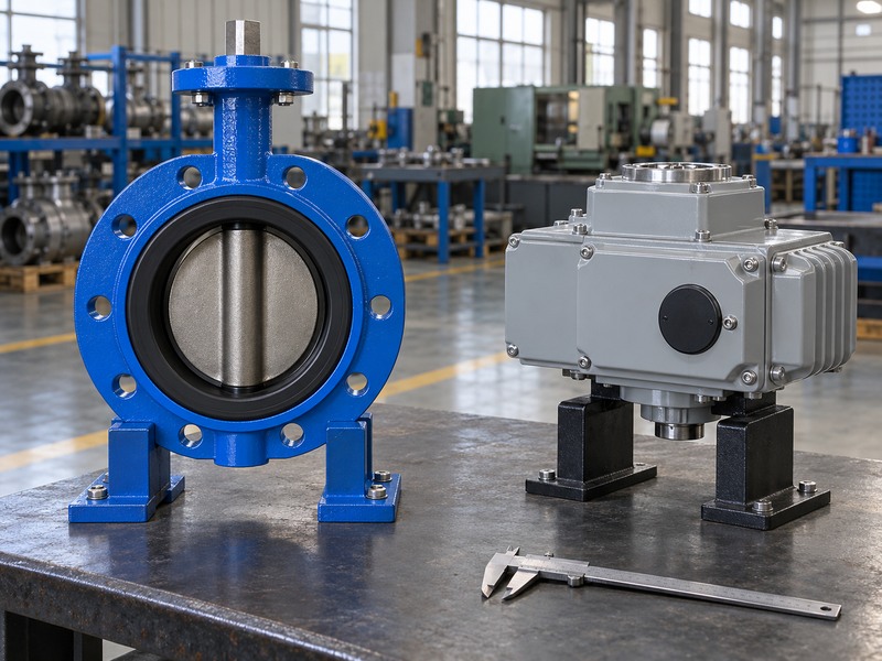
What does a simple power calculation show?
For illustration, mechanical power equals torque multiplied by angular speed. A hypothetical constant 100 Nm output moving through 90 degrees in ten seconds has an average speed of about 0.157 radians per second and an average mechanical power of about 15.7 W. This idealized calculation does not select the motor: input losses, peak torque, acceleration, gear behavior and duty remain unresolved. It explains why converting a catalogue motor rating into an assumed valve torque can give a misleading selection.
- Distinguish electrical input from mechanical output.
- Use the complete actuator's torque-speed data.
- Check peak and duty requirements beyond average power.
| Illustrative quantity | Assumption or calculation | Limit |
|---|---|---|
| Travel and time | 90 degrees in 10 seconds | Assumes the stated motion |
| Average angular speed | About 0.157 rad/s | Does not describe acceleration |
| Mechanical power at 100 Nm | About 15.7 W | Excludes losses and peak requirements |
3. Which supply conditions belong in the sizing basis?
Use the electrical supply conditions permitted at the actuator, including voltage, frequency, phase arrangement and relevant variation during operation. A nominal site supply label does not describe every condition at the motor terminals. Cable losses and simultaneous equipment demand can affect the delivered supply. Ask the actuator supplier to confirm output, starting and protection behavior across the accepted range rather than assuming that every voltage variation leaves rated torque unchanged.
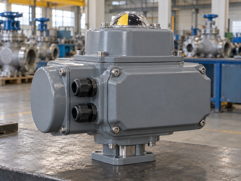
How should procurement describe the electrical package?
Specify the actuator's power supply separately from its control signal and feedback supplies. Include the required connection arrangement, cable-entry constraints and any interface equipment within the supply scope. The electrical design should account for the manufacturer's current and starting data, protective devices and wiring instructions. Do not energize a package from a convenient factory supply unless its configuration permits it. Record any separate controls or transformers required so the quotation does not appear complete while leaving the electrical interface unresolved.
- State power, controls and feedback supplies separately.
- Confirm permissible supply variation with the manufacturer.
- Include required connection and protection information.
| Supply field | What to record | Selection consequence |
|---|---|---|
| Power input | Voltage, frequency and phases | Motor and control configuration |
| Permitted variation | Accepted terminal conditions | Guaranteed output and starting behavior |
| Control interface | Signal and auxiliary supply requirements | Compatible command and feedback arrangement |
4. How do starts and duty affect actuator selection?
Starts, operating time and load determine whether the actuator is suitable for the required cycling pattern. Occasional open-close duty differs from repeated positioning or continuous modulation. A drive rated for short operating periods cannot be assumed suitable for frequent small corrections simply because each movement is brief. Obtain the manufacturer's duty classification, starts limit and applicable load conditions, then compare them with the expected control behavior and ambient conditions.
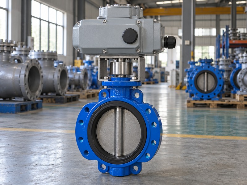
What should a modulation request describe?
State expected movements, starts and running time over a representative period, including start-up or upset conditions. Include the required positioning resolution and the process controller's likely command activity. Published actuator data can distinguish open-close and modulating configurations even within the same housing family, with different permissible torque or starts. Avoid adopting a universal percentage or starts-per-hour value from another model. If the operating pattern changes after commissioning, reassess thermal duty and protection rather than only adjusting the control-loop tuning.
- Describe the expected movement pattern and load.
- Use the selected configuration's duty limits.
- Review start-up and upset cycling as well as normal operation.
| Operating pattern | Data to request | Question to close |
|---|---|---|
| Occasional open-close | Permitted running time and starts | Can the required cycles complete? |
| Frequent positioning | Starts, load and thermal limits | Will repeated corrections remain within duty? |
| Modulation | Rated modulating duty and positioning data | Does the package suit the control requirement? |
5. How should torque and travel settings protect the valve?
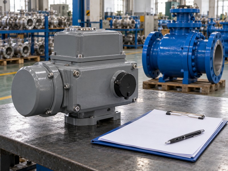
Torque and travel settings must follow the valve's required seating method and the actuator manufacturer's procedure. Some assemblies use position limits for normal stopping; others require a defined seating-torque method. Confirm the accepted arrangement before setting the operator. The drive needs adequate output for the duty, while its maximum possible transmitted torque and protective settings must respect the valve shaft, coupling, bracket and mechanical-stop limits.
Can the torque limit be set to the highest value?
Use the accepted setting range and verification method rather than the actuator's largest available setting. A high limit can allow damage during obstruction or incorrect travel. A limit set too low can interrupt legitimate seating before the valve reaches its required condition. For a lug butterfly valve package, retain the valve's allowable torque and direction-specific requirements with the actuator settings. Investigate repeated trips as an operating or mechanical issue before changing limits to suppress the alarm.
- Confirm position-limited or torque-dependent seating as specified.
- Keep maximum transmitted torque within accepted limits.
- Record settings and their verification conditions.
| Setting | Purpose | Incorrect assumption |
|---|---|---|
| Travel limit | Defines accepted end position | Every valve uses the same stop method |
| Torque protection | Limits specified loading | Highest setting is always preferable |
| Feedback reference | Reports checked position | Signal alone proves sealing performance |
6. Which mounting and access dimensions must match?
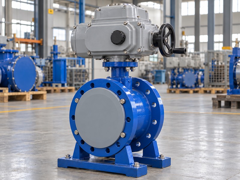
Match the mounting pattern, drive form, coupling engagement, bracket height and complete operator envelope. Include the space needed for cable entries, manual override and removal of covers. A drive can share a mounting designation while requiring another coupling or bracket. Check the package's weight and centre of gravity so the mounting structure carries the accepted loads without distortion or unwanted axial force on the valve shaft.
What does a standard attachment interface establish?
ISO 5211 defines requirements within the part-turn actuator attachment interface scope. Use the exact dimensional callouts and agreed assembly drawing rather than treating the designation as proof that every bracket and coupling detail is suitable. For a flanged butterfly valve assembly, review the operator orientation against pipework and maintenance access. Confirm any additional support arrangement with the assembly designer, and retain the required engagement clearances when selecting a replacement drive.
- Review the complete assembly rather than the bare valve.
- Check coupling engagement without bottoming.
- Include weight, support and maintenance access.
| Assembly feature | Required check | Problem avoided |
|---|---|---|
| Mounting and coupling | Pattern, form and usable engagement | Misalignment or lost motion |
| External envelope | Covers, entries and override access | Inaccessible installed operator |
| Support arrangement | Weight and reaction loads | Distortion or unwanted shaft loading |
7. How do controls and feedback affect the package?
Controls and feedback determine how the actuator receives commands, stops and reports its condition. Specify open-close, positioning or modulating operation with the actual signal and required status outputs. Confirm the loss-of-signal behavior separately from loss of power. A nominal position command does not establish measured disc angle unless the feedback and mechanical references are checked, and it does not establish process flow or shutoff tightness.

Which functions should be included in acceptance?
Define local and remote control behavior, interlocks, fault reporting and the expected position indication. Verify the command direction and actual valve movement together under the agreed procedure. If a process control loop requires accurate low-flow regulation, review the valve's hydraulic characteristic and usable travel alongside actuator positioning performance. Higher signal resolution cannot remove cavitation or an unsuitable valve size. Keep the accepted wiring and configuration records with the assembly so a later control change can be assessed against the original requirements.
- List command, feedback and fault functions explicitly.
- Check indication against actual valve travel.
- Review process control suitability separately from signal compatibility.
| Function | What to specify | What it does not prove |
|---|---|---|
| Command | Signal and operating mode | Adequate valve torque |
| Position feedback | Reference and required behavior | Measured process flow |
| Fault output | Events and response | Suitability for every process condition |
8. What happens when electrical power is lost?
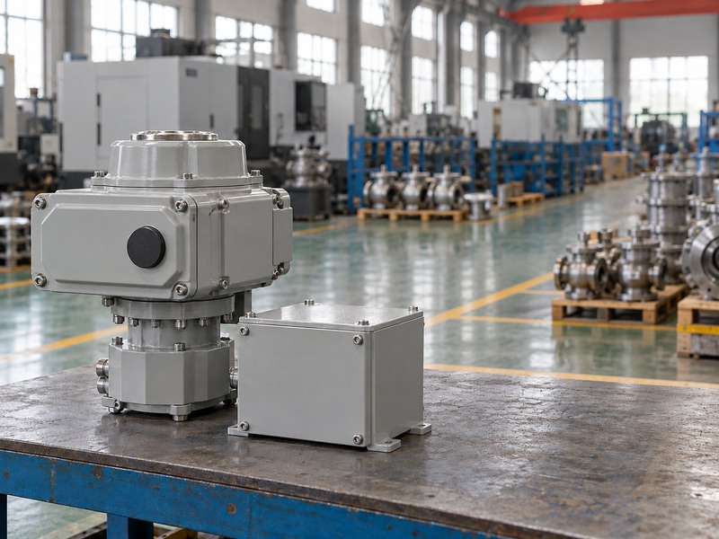
The power-loss response depends on the exact actuator and control arrangement. A conventional motor-driven package may remain in place, while a specified spring or stored-energy arrangement may move the valve to a required position. Confirm the intended response and the conditions it covers. Do not infer automatic closure from an electric actuator's appearance, manual override or a broad product description that does not identify the actual configuration.
How should a stored-energy function be checked?
Specify the required event, final position, travel time and pressure conditions. Obtain the supplier's capability and verification requirements for the selected spring, battery or capacitor arrangement, including applicable environmental and maintenance limits. A successful unloaded return does not prove completion under the governing valve torque. Distinguish a manual recovery option from automatic movement after energy loss. If the process requires a defined response to a lost control signal while power remains available, document and test that as a separate case.
- Define power loss and signal loss separately.
- Check available return output against valve demand.
- Retain configuration-specific maintenance and verification requirements.
| Event | Required definition | Verification question |
|---|---|---|
| Power loss | Hold or move, final position and time | Does the selected package provide that function? |
| Signal loss | Response with power still available | Is the control configuration correct? |
| Manual recovery | Permitted operating method | Is access and the procedure suitable? |
9. What belongs in an electric actuator enquiry?
Include valve torque data, allowable mechanical limits, supply conditions, required speed, operating frequency, control functions and loss-event requirements. Add the mounting drawing, orientation and access envelope. State which accessories and electrical controls are included in the supply scope. This lets the supplier select a complete package and identify deviations rather than returning a motor rating that leaves the operating duty and installation interface undecided.
Which selection records should you retain?
Request the accepted output and duty data, mounting drawing, electrical information, settings and functional verification plan. For RUITO enquiries, contact us with the valve duty sheet and control requirements so the electric package can be reviewed as one assembly. Verify the delivered configuration against that record before commissioning. If the motor, gearbox, controls or valve seat changes, reassess the affected torque, thermal duty and settings before describing the replacement as equivalent.
- Send torque, supply, speed and cycling data together.
- Confirm the full controls and accessory scope.
- Retain settings and configuration under revision control.
| Enquiry area | Required input | Accepted response |
|---|---|---|
| Mechanical duty | Torque, travel and limits | Suitable output and protection |
| Electrical operation | Supply, starts, speed and mode | Configuration-specific duty data |
| Integration | Mounting, controls and loss events | Complete drawing and verification scope |
10. What questions arise when sizing electric valve drives?
Q1. Can I select an electric actuator from motor horsepower?
No. Use the complete actuator's output torque, speed and duty data. Motor power leaves gearing, efficiency, starting behavior and permitted cycling unresolved.
Q2. How do I know if an open-close actuator can modulate?
Check the selected configuration's rated duty, starts, running time and positioning capability. A shared housing or similar torque rating does not establish modulating suitability.
Q3. Can I increase the torque setting when it trips?
Investigate the cause and compare the setting with the accepted valve and mounting limits. Obstruction, seat compression or incorrect travel may require correction. A higher limit can transfer the fault into mechanical damage.
Q4. What's the best closing time for every butterfly valve?
Choose a time accepted for the process and hydraulic system. Fast closure can affect transients, while slow movement may fail the operating requirement. Confirm the selected actuator can meet the agreed time under its actual supply and load.
Q5. Can every electric actuator close automatically after power loss?
No. Automatic return requires a specified and correctly sized arrangement. Confirm its available return output, final position, timing and verification requirements for the actual valve duty.