
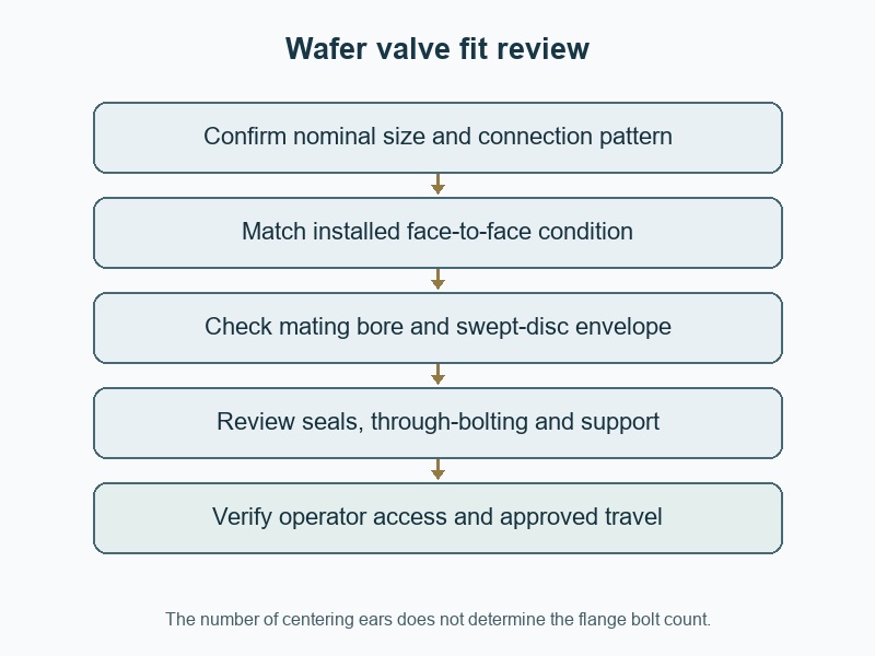
Wafer butterfly valve size must match the nominal pipe designation, accepted flange interface and complete disc-clearance envelope. Compare "wafer butterfly valve sizes" on the exact model drawing before ordering. A short body can fit inside the flange gap while its opening disc still strikes a liner, reducer or neighbouring component.
1. Which wafer butterfly valve sizes are available?
Available sizes depend on the manufacturer's construction, materials and service configuration. RUITO's supplied business data lists ordinary water-service wafer butterfly valves at DN50–600 with PN10/16 configurations, while its stated low-temperature wafer package has a narrower DN50–300 range. Those are starting supply ranges rather than universal limits for all wafer valves. Confirm the selected size with its actual seat, body, connection, drive and operating requirements.
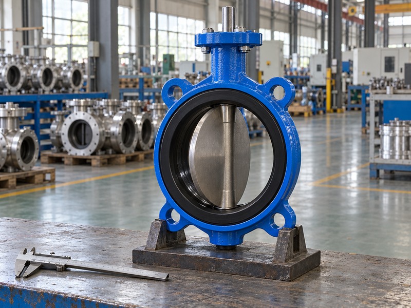
Why should special constructions remain separate?
A lined or specially rated assembly can have another range and different installation details even when its outside body looks familiar. Do not transfer ordinary water-valve dimensions or pressure limits into a chemical-service enquiry. Ask the supplier to identify the exact proposed construction and its drawing. Treat a catalogue endpoint as availability information that still needs configuration confirmation, particularly when a requested size, material or operator falls outside the stated standard range for the intended application.
- Check size range for the exact construction.
- Keep special-service configurations separate.
- Confirm current supply and the accepted interface drawing.
| RUITO starting enquiry | Stated nominal range | Confirm before selection |
|---|---|---|
| Water-service wafer configuration | DN50–600 | Actual material, rating and interface |
| Low-temperature wafer package | DN50–300 | Package-specific fluid and temperature limits |
| Lined or special-service request | Configuration-specific | Connection, dimensions and full service acceptance |
2. How do nominal size and actual bore differ?
Nominal size identifies the pipework designation, while the actual bore depends on the valve and connected pipe geometry. DN100 commonly corresponds to NPS4, but this pairing does not guarantee an opening of exactly 100 mm or four inches. The resilient seat, disc, shaft and pipe wall affect the available passage. Check the specified designation and actual mating profile separately instead of selecting a valve from an isolated bore measurement.
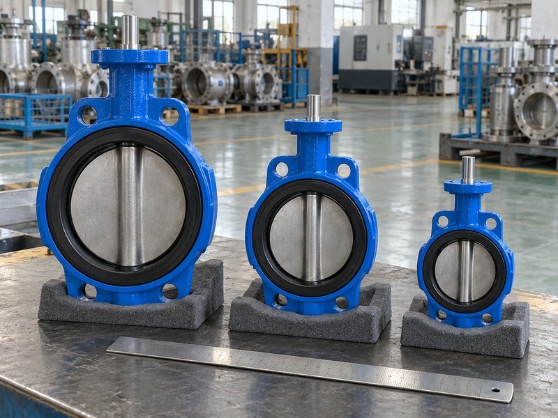
Which dimensions belong in a field survey?
Record the valve identification, measured opening surfaces and units. ISO 6708 defines the DN designation system; use nominal terminology without turning it into an exact measurement. For an installed line, obtain the pipe schedule and lining information or identify what must be checked during an approved inspection opportunity. A pipe's outside diameter or circumference alone cannot establish the internal clearance available for the wafer valve's disc, especially where thick walls or linings reduce the passage.
- Record DN or NPS as a designation.
- Identify the actual surfaces contacted during measurement.
- Obtain pipe wall and lining information for clearance review.
| Nominal pairing | What it identifies | Separate physical check |
|---|---|---|
| DN50 / NPS2 | Corresponding nominal size | Actual valve and pipe bore |
| DN100 / NPS4 | Corresponding nominal size | Seat profile and disc envelope |
| DN150 / NPS6 | Corresponding nominal size | Connected pipe and lining profile |
3. Which body length should fit the flange gap?
Use the specified installed face-to-face condition, with its defined reference faces and sealing arrangement, to review the flange gap. A resilient seat may extend beyond the metal casting, and its compression can affect installation dimensions. Measuring only the short metal body can omit that feature. Confirm the dimensional series and model drawing rather than assuming that every wafer valve with the same DN has the same free-state or installed length.
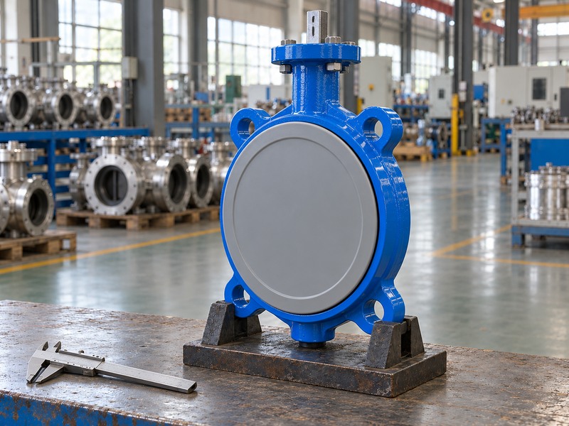
How should a replacement length be checked?
Measure the existing flange gap and record alignment separately from the removed valve's dimensions. Compare both with the proposed drawing, including any approved separate gasket allowance. Do not use flange bolts to pull misaligned piping into place or compress an unsuitable stack to the desired length. If a replacement needs a spool change, review that work before the valve is ordered. The short axial envelope of a wafer body is useful only when its complete installed arrangement matches the line.
- Identify free-state and installed reference conditions.
- Check the actual gap and flange alignment.
- Resolve required pipework changes before ordering.
| Length item | Record | Common error |
|---|---|---|
| Metal body | Specified casting or machined faces | Ignoring projecting seat faces |
| Installed face-to-face | Approved sealing condition | Copying a free-state value |
| Available gap | Actual mating flange faces | Using bolting to correct misalignment |
4. Which mating flange details must match?
Confirm the flange standard, pressure designation, drilling, facing, contact area and internal bore on both sides of the valve. Matching a few holes cannot establish the whole interface. A wafer body may be offered for more than one flange pattern, but the supplier still needs to accept the exact mating configuration. Keep the pipe flange material and sealing-face limitations visible alongside the nominal diameter and bolt circle.
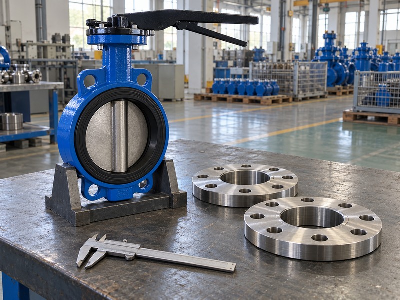
How does this differ from a lug connection?
A wafer assembly commonly depends on the two pipe flanges and spanning fasteners to retain the valve. A lug butterfly valve commonly uses threaded bosses and separate fasteners from each side. Their retention, length and end-duty checks differ, even when some overall dimensions are similar. Do not turn a wafer centering ear into a tapped-lug assumption. For either construction, the accepted joint needs suitable contact for the specified seat or gasket and adequate clearance for the moving disc.
- Review both mating flanges and their material.
- Confirm the complete sealing-face contact.
- Keep wafer and lug fastening arrangements distinct.
| Interface field | What to confirm | Why drilling alone is insufficient |
|---|---|---|
| Standard and class | Accepted flange designation | Similar holes can hide other differences |
| Facing and material | Suitable supported seal contact | Local loading and contact may differ |
| Bore | Actual minimum internal profile | Disc can strike the connected component |
5. How do you check the opening disc's full envelope?
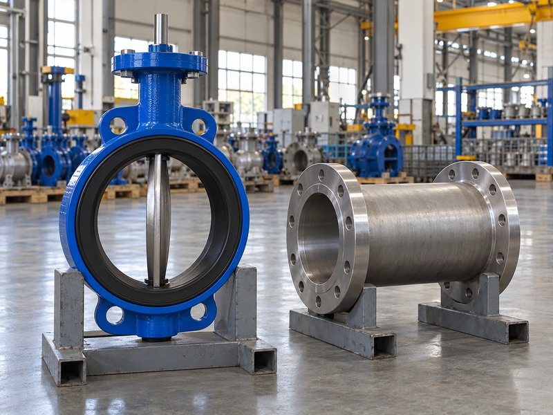
Check the complete swept-disc envelope against the actual pipe and neighbouring components throughout the approved travel. The disc may project outside the short wafer body when it opens. A reducer, liner, weld intrusion or adjacent valve can enter that moving space despite a matching flange pattern. Obtain the exact valve's clearance data and the distance of each potential obstruction from the defined valve faces.
Can a short straight spool solve the problem?
A suitable spool can provide space in some reviewed arrangements, but its diameter, length and position need to be checked with the actual disc envelope. Adding an arbitrary spacer does not prove adequate clearance and changes the joint's axial stack and fastener lengths. Review the complete arrangement before accepting it. Under the approved isolated and depressurized installation procedure, verify travel without forcing resistance; a stronger actuator cannot correct physical interference between the disc and a nearby fitting.
- Check upstream and downstream components.
- Describe obstruction position as well as diameter.
- Review spacers or spool changes as complete joint changes.
| Potential obstruction | Data needed | Possible review outcome |
|---|---|---|
| Pipe lining or thick wall | Minimum internal profile | Confirm clearance or change arrangement |
| Reducer | Taper and distance from the valve | Check the whole swept envelope |
| Adjacent valve or fitting | Internal projection and spacing | Coordinate both components' movement |
6. Should you add separate flange gaskets?
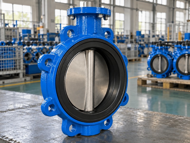
Use separate gaskets only when the selected valve's approved installation arrangement requires or permits them. Some resilient seats form the flange sealing faces, while other constructions use specified separate seals. Adding a gasket by habit can change contact, compression, face length and disc clearance. The correct answer comes from the exact valve and mating flange instructions rather than a universal rule for every product described as a wafer butterfly valve.
Which conditions should the installer compare?
Review flange flatness, facing geometry, material, supported contact area and the specified tightening procedure. A lined assembly needs particular attention to its flange-facing and compression limits; appearance cannot establish the correct gasket arrangement. If the existing installation used an extra seal, identify why it was present before copying it into the replacement. Keep any proposed change in the accepted joint detail, then update the fastener length calculation and clearance review where the axial stack changes.
- Follow the exact configuration's sealing instructions.
- Record separate gasket use explicitly.
- Recheck stack length and load when the seal arrangement changes.
| Sealing arrangement | Confirm | Avoid |
|---|---|---|
| Seat forms flange seal | Required contact and compression | Automatic extra gaskets |
| Separate gasket specified | Type, dimensions and procedure | Uncontrolled substitution |
| Lined flange face | Accepted support and tightening limits | Assuming ordinary water-valve practice applies |
7. How do bolt lengths and centering ears affect installation?
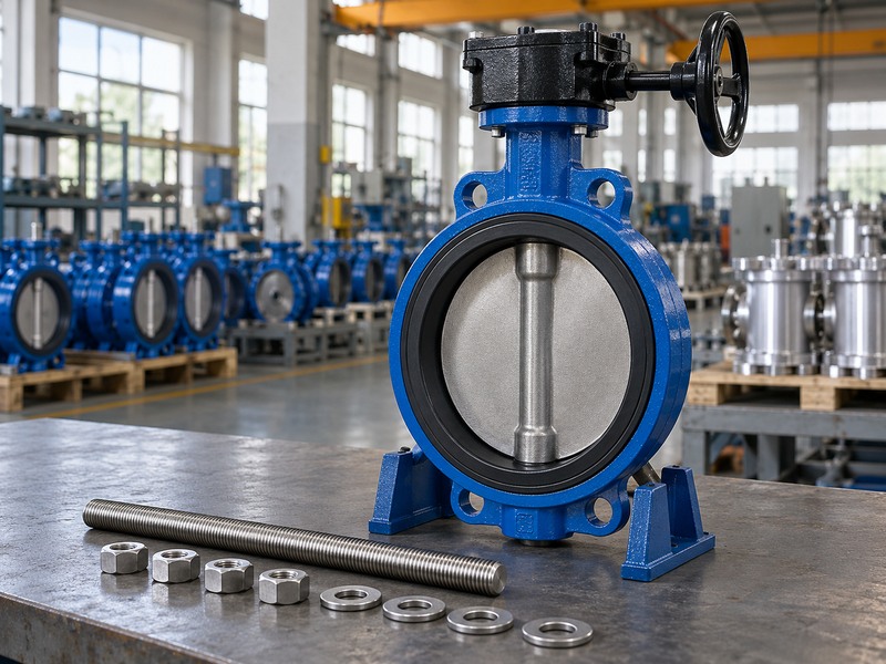
Bolt lengths must suit the complete joint stack and all position-specific restrictions. Count the accepted mating flange pattern rather than the valve's centering ears. Some wafer designs need special fasteners near the neck where a continuous through-path is unavailable. The required set therefore comes from the accepted assembly drawing, including flange thickness, seals, washers, nuts and projection requirements, rather than one generic bolt length selected from DN.
Can a wafer valve be treated as an end-of-line closure?
An ordinary wafer retention arrangement should not be assumed suitable when one pipe flange or downstream section is removed. Any end-of-line duty needs the exact approved valve arrangement, pressure limits, restraint and isolation procedure. If that function is required, state it during selection and compare a suitable retaining construction rather than inferring approval from a closed disc. For normal installation, verify fastener access and the complete clamping arrangement before applying the specified staged tightening procedure.
- Use the flange pattern to determine positions.
- Identify neck-area fastener exceptions.
- Specify any end-duty requirement independently.
| Fastening feature | Required review | Incorrect shortcut |
|---|---|---|
| Centering ears | Valve location between flanges | Using ear count as total bolts |
| Through-fasteners | Complete stack and access | One universal length per DN |
| End-of-line duty | Approved retaining arrangement and limits | Assuming a closed wafer disc provides approval |
8. Which drive and service limits remain after fit checks?
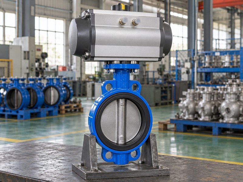
Drive torque, mounting geometry, material compatibility and pressure-temperature limits remain separate from physical fit. A wafer valve that fits the flange gap can still be unsuitable for the fluid or unable to close under the required differential. Check the selected operator's envelope and mechanical interface alongside the valve duty. Compact body length does not eliminate the space needed for a lever sweep, handwheel, actuator connections or later maintenance.
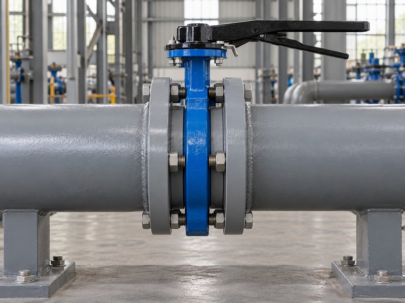
How should the complete package be compared?
Use a coordinated drawing and duty sheet for the actual body, seat and drive. State normal and limiting pressure cases, temperature, fluid composition and the required response to loss of energy. If a double-flanged butterfly valve is proposed as an alternative, review its different length, joint and support requirements instead of treating it as a direct dimensional substitute. Keep any change to the operator, materials or body construction visible until engineering has accepted the full replacement arrangement.
- Review fit, service and actuation as separate checks.
- Include the complete operator and maintenance space.
- Reassess alternatives that change construction or connection.
| Review area | Required evidence | Fit cannot establish |
|---|---|---|
| Service | Fluid and configuration-specific limits | Material compatibility |
| Actuation | Torque and complete mounting data | Adequate output or shaft protection |
| Assembly envelope | Operator and access drawing | Maintenance clearance |
9. What should you send for a wafer replacement enquiry?
Send the valve identification, dimensioned survey, mating flange details and operating requirements as one package. Include actual flange gap, pipe bore and lining, nearby obstructions, sealing arrangement and fastener access. State whether the existing drive will be retained. Mark measurements that are unconfirmed or derived from old drawings so the supplier can identify which checks must be completed before an interchangeable replacement is accepted.
How do you confirm the final configuration?
Request a marked drawing that accepts the installation references and lists any required changes. For RUITO enquiries, contact us with the survey and service data so the proposed wafer assembly can be reviewed against both fit and duty. Retain the accepted drawing, fastener schedule and installation instructions with the order. Before assembly, compare the delivered valve and operator with that record and resolve an unexpected seat, body length or mounting difference before tightening the joint.
- Send interface and service information together.
- Identify retained and replacement components.
- Close deviations before installation begins.
| Enquiry input | Include | Decision supported |
|---|---|---|
| Physical survey | Gap, drilling, bore and obstructions | Installation fit |
| Service data | Fluid, temperature and pressure cases | Suitable configuration |
| Assembly scope | Drive, seals and fasteners | Complete accepted replacement |
10. What questions arise when selecting wafer valve sizes?
Q1. Can I replace a wafer valve using DN alone?
No. Confirm body length, flange interface, seal arrangement, disc clearance, fastening and drive details. Equal nominal size does not establish an interchangeable assembly.
Q2. How do I know whether the open disc clears the pipe?
Compare the model-specific swept envelope with the actual pipe bore and nearby component profiles. Include liners, reducers and their distances from the valve reference faces.
Q3. Can I add gaskets to every wafer valve?
Follow the exact valve's installation instructions. Some seats also seal against the pipe flange, while other constructions require separate seals. An added gasket can change compression and the joint stack.
Q4. What's the best bolt count for a four-ear wafer body?
Use the accepted mating flange pattern and position drawing. Four centering ears do not mean four total fasteners, and some neck locations may require special bolting.
Q5. Can I remove downstream piping from a closed wafer valve?
Only under an arrangement explicitly approved for that duty and the site's isolation procedure. Ordinary wafer retention must not be assumed to remain suitable after a mating flange or pipe section is removed.