
Resolve butterfly valve tamper switch wiring gaps with a contact schedule that identifies the supplied switch, reference states, assigned duties and selected monitored input. Assign responsibility for each interface before accepting the package. The supplier’s lead table, installation record and panel configuration must describe the same electrical function.
A supplier’s lead table can identify every conductor while the project documents leave the chosen contact function or circuit termination undefined. The field team then receives a complete-looking cable schedule with unresolved design decisions. Close those gaps in a controlled interface record that states what each party supplies, checks and accepts.
1. What defines butterfly valve tamper switch wiring scope?
The scope of butterfly valve tamper switch wiring begins with the identified switch arrangement and ends at the accepted system interface. Define which documents cover factory leads, field terminations, the monitored input and panel configuration. A supplier diagram cannot fill an undefined project boundary merely because its drawing includes a generic panel box.
What should the electrical interface record contain?
Define the handover points. Record the supplied assembly, designated contact functions, field connection reference and selected input documentation. State who resolves missing information and who accepts each completed interface under the project’s arrangements. This record should let purchasing distinguish an included factory component from a field-supplied item and an unresolved system-design decision.
- Identify the actual supplied switch and operator configuration.
- Define factory, field and system interface boundaries.
- Assign unresolved questions to a responsible project party.
Key takeaway: Define electrical scope through documented interfaces before treating a lead table as complete design information.
| Check | What you should confirm |
|---|---|
| Supply | Factory components and lead functions are identified |
| Field | Installation scope and connection references are defined |
| System | Selected input and panel configuration have assigned owners |
2. Who owns butterfly valve tamper switch wiring interfaces?
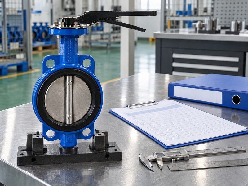
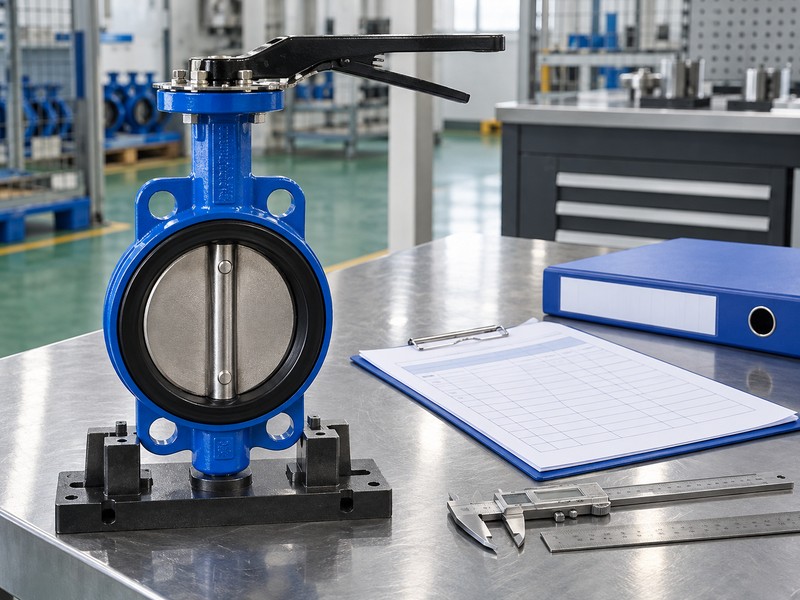
Assign butterfly valve tamper switch wiring interfaces to the responsible supplier, installer and system-design parties through the approved project arrangements. The supplier confirms the actual switch configuration, the installer records field connections, and the responsible system specialist accepts input compatibility and configuration. Confirm those responsibilities against the contract and project process rather than assuming a universal division.
Which decisions should cross each handover?
Assign a named reviewer. The valve-side record needs contact identity and permitted duty, while the field record needs accepted cable and termination references. The system-side record needs a selected compatible input, expected event behavior and approved configuration. Each party should receive the accepted information from the adjoining interface, with deviations resolved before its own record closes.
- Obtain supplier confirmation of the supplied contact arrangement.
- Link field records with accepted circuit and cable references.
- Assign input selection and configuration acceptance explicitly.
Key takeaway: Make responsibility visible at each handover so unresolved design choices do not reach the field unnoticed.
| Check | What you should confirm |
|---|---|
| Supplier | Confirms the identified switch and permitted contact functions |
| Installer | Records field work against accepted circuit documents |
| System reviewer | Accepts compatible input and required reporting configuration |
3. Which states govern butterfly valve tamper switch wiring?
The states governing butterfly valve tamper switch wiring come from the selected contact reference and required valve position. Common, NO and NC describe switching relationships against a defined reference condition. The normal service position of the valve needs its own statement, because a physically open valve does not establish one universal contact path.
How should the contact schedule describe its reference?
Name the physical condition. State the valve position depicted by the manufacturer diagram beside the contact identifiers and expected continuity. The TYCO BFV-300/BFV-300C technical sheet identifies distinct open-supervised and closed-supervised configurations. A schedule entry should retain that model-specific reference rather than reducing the requirement to an unexplained NC or NO abbreviation.
- Identify the diagram’s contact and valve-position references.
- Describe expected continuity for the required service condition.
- Keep the selected model linked to the contact schedule.
Key takeaway: Record contact terminology and valve position together without treating them as the same definition.
| Check | What you should confirm |
|---|---|
| Common | Terminal identity belongs to the actual switching arrangement |
| Contact state | NO or NC label retains its documented reference |
| Valve state | Required physical position is separately defined |
4. Which duties fit butterfly valve tamper switch wiring?
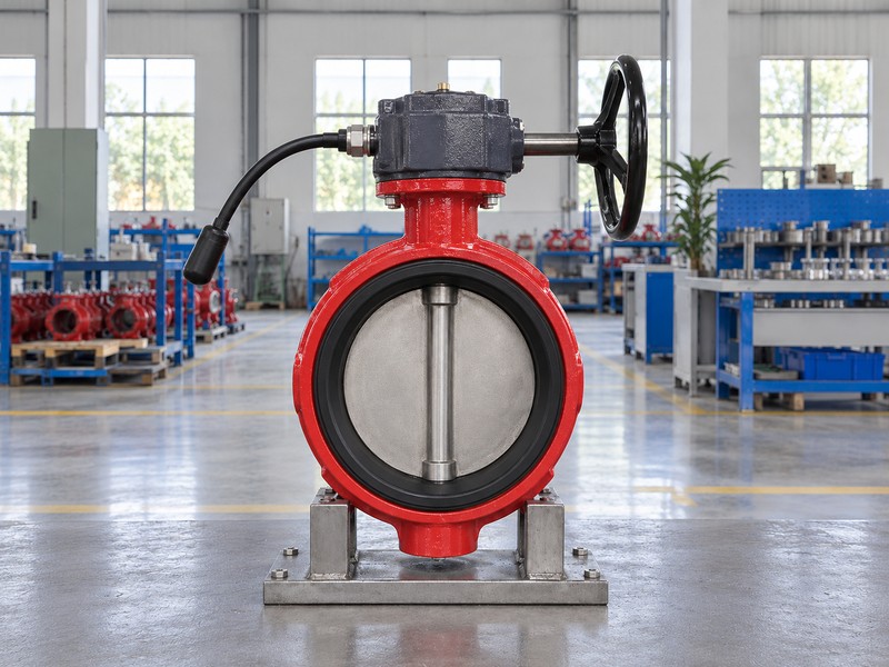
The duties assigned in butterfly valve tamper switch wiring must preserve the selected manufacturer’s supervisory and auxiliary functions. Contact sets inside one operator can have different lead provisions and permitted connections. A spare contact that changes during valve movement cannot automatically replace the designated supervisory connection.
What should separate the supervisory and auxiliary entries?
Preserve each assigned duty. The Victaulic installation and wiring instructions permit the identified S1 arrangement for the fire-alarm connection and distinguish the auxiliary S2 function. Record the selected arrangement’s actual restrictions in separate schedule entries. Any auxiliary load, local indication or other permitted use needs its own circuit definition rather than borrowing the supervisory input’s approval.
- Identify the contact designated for system supervision.
- Keep auxiliary function and circuit ownership separate.
- Preserve manufacturer-specific lead provisions and connection restrictions.
Key takeaway: Assign duties from the actual product documents rather than from the number of available contacts.
| Check | What you should confirm |
|---|---|
| Supervisory | Designated contact serves its permitted monitored function |
| Auxiliary | Separate contact has an identified permitted duty |
| Restriction | Selected manufacturer’s connection limits remain visible |
5. Can butterfly valve tamper switch wiring supply power?
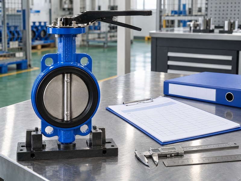
A dry-contact function in butterfly valve tamper switch wiring changes continuity rather than providing a source of operating voltage. Its contact rating states permitted switching duty under specified conditions. Required sensing circuits, module power and any auxiliary supplies come from the selected connected equipment documents.
Which electrical ratings belong in the schedule?
Keep ratings and supplies separate. Record applicable contact limits and the connected input requirements with their document references. An AC or DC contact rating cannot establish the supply required by a monitored input, and matching voltage labels alone cannot approve electrical compatibility. Any separately powered auxiliary device needs its own supply, load and contact-duty review under the selected circuit design.
- Identify the function as dry contact where specified.
- Record contact duty separately from required equipment supplies.
- Compare the selected input with applicable contact limits.
Key takeaway: Treat contact ratings as limits and derive supply requirements from the selected equipment.
| Check | What you should confirm |
|---|---|
| Contact | Switching function and permitted duty are documented |
| Input | Connected circuit requirements follow selected equipment instructions |
| Auxiliary power | Separate devices have their own accepted supply and load basis |
6. What grounds butterfly valve tamper switch wiring?
Grounding provisions in butterfly valve tamper switch wiring follow the selected product and applicable installation requirements. The contact’s common terminal belongs to its switching function, while a designated case-ground connection belongs to the specified bonding arrangement. Keep those roles separately identified instead of treating common as another name for protective ground.
How should grounding and signal references stay distinct?
Label conductor functions explicitly. Retain the actual product’s case-ground or bonding reference beside its separate contact identifiers. Do not infer a conductor’s role from a familiar color on a different manufacturer’s assembly or from the word common alone. The responsible electrical reviewer should resolve grounding, shielding and signal-reference requirements through the selected documents, with any permitted relationship explicitly recorded.
- Identify contact common through the actual switch diagram.
- Identify designated grounding provisions through the selected instructions.
- Retain separate conductor functions in field and interface records.
Key takeaway: Keep contact common and designated protective grounding distinct throughout the interface record.
| Check | What you should confirm |
|---|---|
| Switch common | Identifier belongs to the defined contact function |
| Case ground | Connection follows the selected grounding or bonding arrangement |
| Record | Signal and protective functions retain explicit separate definitions |
7. Which input fits butterfly valve tamper switch wiring?
The input fitting butterfly valve tamper switch wiring is the compatible monitored circuit selected for its designated contact function. Identify the actual panel input or monitor-module channel and its accepted system use. A dry-contact pair is not itself an addressable panel-bus device.
How should the record distinguish IDC from SLC?
Identify both module interfaces. Ordinary valve contacts belong on the selected monitored input, identified as an initiating device circuit or IDC where that module uses the term. The compatible module’s signal line circuit or SLC connects to its panel bus; ordinary contacts do not connect directly across it. Retain the actual module, channel, compatible panel and configuration references so the interface remains identifiable after a component change.
- Name the actual monitored input and assigned contact function.
- Keep the contact circuit separate from the SLC interface.
- Record module, channel and compatible panel identities.
Key takeaway: Approve contact-input compatibility and module-panel compatibility as separate connected interfaces.
| Check | What you should confirm |
|---|---|
| Monitored input | Selected circuit accepts the designated contact function |
| SLC | Compatible module joins its specified panel bus |
| Configuration | Actual channel and accepted system use remain traceable |
8. Which EOL fits butterfly valve tamper switch wiring?
The EOL arrangement fitting butterfly valve tamper switch wiring follows the selected input’s topology, specified component and termination location. A generic resistor symbol cannot establish those requirements. Put the controlling module or panel reference in the interface schedule so the installer receives an accepted circuit definition.
What must the termination entry state?
Use the selected circuit definition. Record the required EOL component, location and permitted circuit arrangement from the actual input instructions. A different topology or module can change the termination method and interpretation of activation or faults. Keep the entry open when those decisions remain unresolved; copying a familiar resistor value or placing a placeholder in the schedule cannot establish supervised field-circuit performance.
- Reference the selected input’s required EOL component.
- Identify termination location through the approved circuit drawing.
- Retain the associated topology and expected reporting behavior.
Key takeaway: Define EOL requirements through the actual monitored-input design before closing the interface entry.
| Check | What you should confirm |
|---|---|
| Component | Specified termination matches the selected input documents |
| Location | Accepted field arrangement identifies the required termination point |
| Topology | Circuit arrangement and expected reports have a documented basis |
9. What proves butterfly valve tamper switch wiring intent?
An accepted state-and-event schedule establishes the intended behavior of butterfly valve tamper switch wiring for the selected system. Relate the required physical condition and contact state to its intended supervisory report. Record specified circuit-fault responses separately, since their interpretation depends on the actual input design and configuration.
Which results should commissioning compare with the schedule?
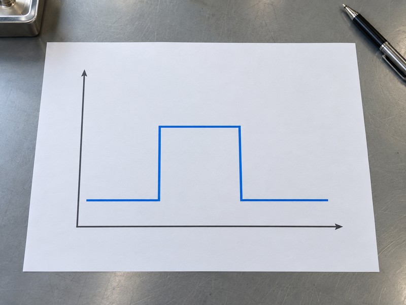
Write expected outcomes before testing. The responsible system parties should accept the normal condition, required departure report and restoration criteria against selected product and project documents. Authorized commissioning then compares actual behavior with those entries and records the result. The abstract chart illustrates initial, changed and restored states only; its levels and spacing establish no contact polarity, electrical value, travel or response-time requirement.
- Define required valve and contact conditions together.
- Record intended supervisory and specified fault reports distinctly.
- Compare authorized test results with accepted schedule entries.
Key takeaway: Use the accepted state-and-event schedule as the reference for functional verification.
| Check | What you should confirm |
|---|---|
| Initial | Required condition has an accepted normal-report definition |
| Changed | Specified contact behavior maps to the intended system event |
| Restored | Required physical and reporting states have accepted closure criteria |
10. Who accepts butterfly valve tamper switch wiring records?
The responsible project parties accept butterfly valve tamper switch wiring records under their assigned review and handover process. Close supplier configuration, field installation and system reporting questions against their required evidence. A completed schedule cannot establish product approval or installed performance without the supporting records required for that project.
What should remain controlled after acceptance?
Retain the accepted interface. Keep as-built contact schedules, selected manuals, installation references, approved deviations and verification results linked to the actual assembly. Review replacements against affected contact duties, circuit requirements and approval coverage before accepting a revised configuration. RUITO can review an identified valve-assembly request and related product documents; responsible project professionals retain electrical design, commissioning and system acceptance duties.
- Match accepted records with actual supplied and installed identities.
- Retain deviations and affected functional verification results.
- Review changed components before revising the accepted interface.
Key takeaway: Accept a traceable interface package whose records describe the same supplied and installed function.
| Check | What you should confirm |
|---|---|
| Supply record | Actual switch arrangement and permitted duties are retained |
| Field record | Installation references and accepted deviations describe the work |
| System record | Input configuration and verification results match the assembly |
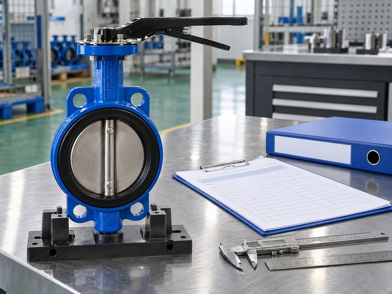
Send RUITO your identified valve-assembly request, supplied switch documents, proposed contact schedule and unresolved product questions. We can review the requested valve configuration and clarify which assembly records your team still needs. Contact us before releasing a purchase whose supervisory contact identity or permitted function remains undefined.
FAQ
Q1: Can I use common as the case-ground connection?
Do not equate those functions. Contact common belongs to the switch arrangement; designated grounding follows the selected product and installation requirements.
Q2: What’s the best record to request from the supplier?
Request the identified contact arrangement. Include the supplied model, lead identifiers, position reference, permitted duties and matching document revision.
Q3: How do I know if the switch needs a power supply?
Read the selected component documents. A dry-contact rating defines switching duty; module power and monitored-input requirements have separate specifications.
Q4: Can I connect valve contacts directly across the SLC?
No. Ordinary valve contacts use the selected monitored input; a compatible module connects separately to the panel bus.
Q5: How do I know who decides the EOL arrangement?
Check the assigned project responsibility. The accepted decision must follow the selected input’s component, topology and termination-location requirements.