
Fix package-matching mistakes by checking actual valve demand against available actuator output and every connected-part limit. An electric double offset butterfly valve also needs defined duty, supply, controls, feedback and failure behavior. Accept those functions as one identified package with supporting mechanical and electrical records.
An actuator can share the valve’s mounting pattern yet lack the output required to unseat its selected trim at the actual differential. Choosing a larger unit without reviewing shaft and coupling limits can create another unresolved load case. Start with the selected valve’s operating demands, then review both sides of the permitted torque range before releasing the package.
1. What defines an electric double offset butterfly valve?
An electric double offset butterfly valve package combines an identified valve construction with a selected electric actuator, coupling and mounting arrangement. Double-offset geometry and electric operation describe different parts of that package. Neither description establishes the seat, body style, torque demand or complete set of operating functions.
Which identities should the package schedule retain?
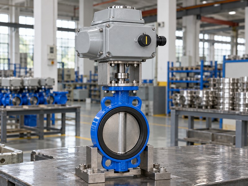
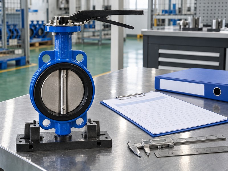
Identify the complete package. Record valve model, size, body style, seat and materials alongside actuator identity, mounting parts and required functions. A proposed RUITO configuration needs confirmation through its own documents; separate wafer and double-flanged product descriptions cannot establish a combined electric wafer double-offset offer. A generic powered-actuator image cannot verify internal valve geometry, actual output or package availability.
- Identify the actual valve, actuator and mounting components.
- Keep body style and offset geometry separately defined.
- Record required functions against the selected package identity.
Key takeaway: Review one identified package with a defined mechanical and electrical scope.
| Check | What you should confirm |
|---|---|
| Valve | Body, seat and construction describe one selected assembly |
| Operator | Electric actuator model and options are identified |
| Package | Coupling, mounting and required functions remain traceable |
2. What torque drives an electric double offset butterfly valve?
Valve demand in an electric double offset butterfly valve includes the applicable seating, unseating, running and fluid-torque cases. Obtain those demands for the actual seat, medium, temperature and differential pressure. A general claim of reduced seat rubbing cannot supply the required actuator-sizing values.
Which operating conditions belong with the torque data?
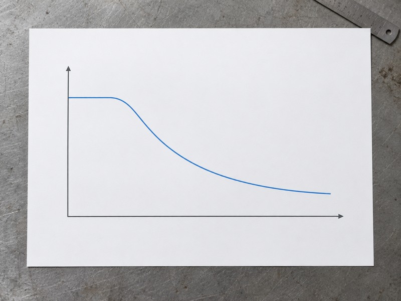
State the actual valve duty. The Bray McCannalok technical manual separates seating and unseating data by identified configurations, differential and orientation. Retain the demanding opening and closing cases rather than assuming line pressure alone defines demand. The conceptual pressure-temperature chart shows no torque curve or sizing result; actual valve limits and torque information remain separate selected-product records.
- Obtain demand for seating, unseating and required movement.
- State actual differential, temperature, medium and direction.
- Keep the selected valve data with its operating-case definitions.
Key takeaway: Size from documented valve demand for the actual service and operating cases.
| Check | What you should confirm |
|---|---|
| Opening | Unseating and movement demands match the actual duty |
| Closing | Selected seat and differential define required torque cases |
| Basis | Media, temperature and orientation accompany the values |
3. What output suits an electric double offset butterfly valve?
The actuator for an electric double offset butterfly valve must cover required valve demand at its actual available input conditions. Review minimum available output where it matters through movement and at seating. Also compare maximum transmitted output with the permitted shaft, coupling, bracket and connected-drive limits.
Why must both output boundaries be reviewed?
Compare demand, capacity and limits. The Keystone K-LOK technical sheet gives configuration-specific torque information for its identified family, illustrating why the actual valve matters. Retain the selected actuator’s available-output basis and applicable settings or protective functions where supplied. An unexplained safety factor or larger nameplate value cannot replace review of demand and permissible connected-part loads.
- Check minimum available output for each required demand case.
- Review maximum transmitted loads against connected-part limits.
- Retain the justification for any selected sizing allowance.
Key takeaway: Match the package between adequate available output and acceptable maximum loads on its connected parts.
| Check | What you should confirm |
|---|---|
| Demand | Actual valve duty establishes the required operating torque |
| Available output | Selected actuator data covers actual input conditions |
| Upper limits | Shaft and mounting components retain their permissible loads |
4. What duty suits an electric double offset butterfly valve?
An electric double offset butterfly valve needs an operating-duty definition covering movement frequency, speed and the intended control task. Occasional isolation and repeated modulation can impose different actuator requirements. Required travel time must also suit the selected valve and process rather than follow a universal fast-closing preference.
What should the duty and speed schedule include?
Define the movement pattern. State whether the package performs open-close service, positioning or modulation, then identify required operating frequency and permitted travel behavior. Request the selected actuator’s applicable duty and speed information under its actual service conditions. Where closing behavior affects the piping system, retain the project’s transient or process review rather than assuming the fastest available setting is acceptable.
- State isolation, positioning or modulation duty explicitly.
- Identify movement frequency and required travel behavior.
- Retain actuator duty limits and process-related speed requirements.
Key takeaway: Choose actuator duty and speed for the actual movement pattern and accepted process requirements.
| Check | What you should confirm |
|---|---|
| Task | Required operating mode matches selected actuator capability |
| Frequency | Movement pattern stays within the accepted duty basis |
| Speed | Travel behavior suits the valve and process review |
5. What supply suits an electric double offset butterfly valve?
Supply requirements for an electric double offset butterfly valve belong to its selected actuator and control arrangement. Record the available electrical supply and the actuator’s actual nameplate or selected configuration data. Motor power, control power and signal interfaces can have different definitions that need explicit project documentation.
Which electrical assumptions must sizing retain?
Keep supply and performance linked. Request the selected equipment’s permitted supply conditions, relevant loading information and associated output or duty restrictions. Distinguish the actuator’s motor supply from control commands and feedback circuits without assuming universal voltages, wire colors or terminal functions. Electrical design, protective devices and site connections follow the selected equipment documents and authorized project arrangement rather than a generic valve connection recipe.
- Record available supply and selected actuator requirements.
- Separate motor, control and signal interface definitions.
- Keep supply assumptions with output and duty verification.
Key takeaway: Retain supply requirements and their effect on available output and duty.
| Check | What you should confirm |
|---|---|
| Motor supply | Actual equipment requirements match the available source |
| Controls | Command and control-power interfaces are separately defined |
| Performance | Output and duty data retain their stated supply basis |
6. What controls an electric double offset butterfly valve?
Controls for an electric double offset butterfly valve must match the intended command and indication functions. Identify required local or remote operation, interlocks and feedback without assuming every actuator contains the same options. A command sent to the operator does not prove that the disc reached its accepted position.
How should commands and feedback be distinguished?
Define each control function. Record command type, operating modes, required feedback and the project interface responsible for interpreting each indication. Where supplied, limit indications, continuous position signals and actuator status outputs have their own documented meanings. Review the mechanical drive relationship alongside the signal definition so operator feedback is not treated as direct proof of seat tightness or an intact connection everywhere in the package.
- Identify required operating modes and command interfaces.
- Define each supplied feedback or status indication.
- Keep signal meaning separate from hydraulic and mechanical proof.
Key takeaway: Accept control and feedback functions by their documented meaning within the actual mechanical package.
| Check | What you should confirm |
|---|---|
| Command | Defined input requests the accepted operating task |
| Feedback | Selected output reports its documented position or status |
| Interface | Project records define interpretation and responsibility |
7. What fails safe in an electric double offset butterfly valve?
Failure behavior of an electric double offset butterfly valve needs an explicit project requirement and an identified equipment basis. Loss of motor supply, loss of a command signal and a control-system fault are different events. Electric operation alone cannot establish a particular final valve position or guaranteed powered movement after supply loss.
Which failure cases need separate acceptance criteria?
Specify the required response by event. Record the intended action, any required position and the selected means of achieving that action, including any documented supplementary equipment where applicable. Keep each claim within the supplied configuration instead of assuming energy storage, automatic return or a retained position. Verification follows the selected equipment and authorized project procedure, with the required observations and response ownership agreed before testing.
- Separate supply loss, signal loss and defined control faults.
- Identify required behavior and the supplied means of achieving it.
- Retain selected acceptance criteria and authorized verification scope.
Key takeaway: Specify failure behavior for defined events and the means supplied to achieve it.
| Check | What you should confirm |
|---|---|
| Event | Project defines the particular failure condition |
| Response | Required action has an identified equipment basis |
| Evidence | Accepted procedure verifies the stated package behavior |
8. What access suits an electric double offset butterfly valve?
An electric double offset butterfly valve needs a mounting and service envelope suited to the actual operator. Review coupling engagement, alignment, bracket loads and clearance around the electric enclosure. Where a manual override is supplied, its access and permitted use also belong to the selected package review.
Which mounting and override details should remain visible?
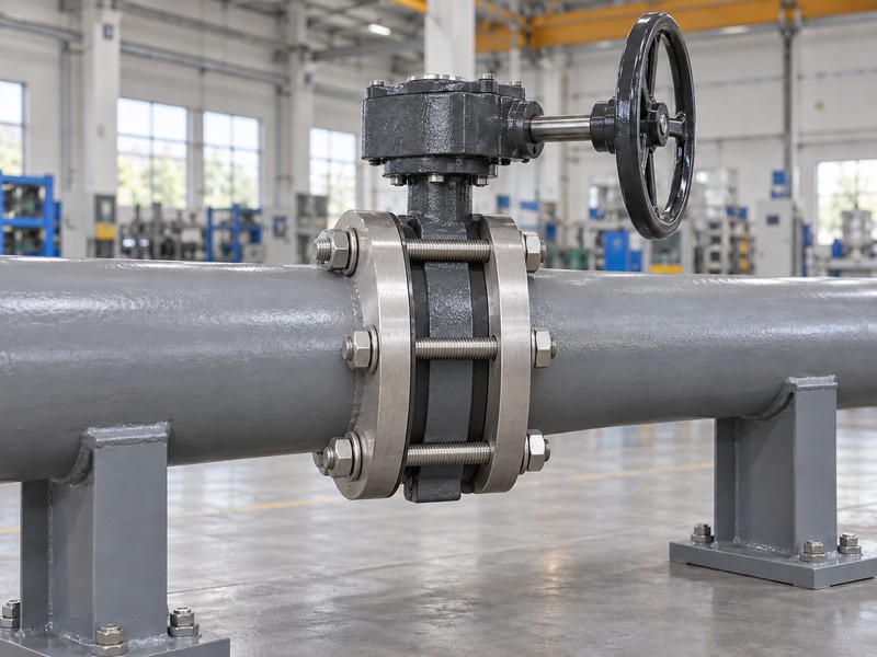
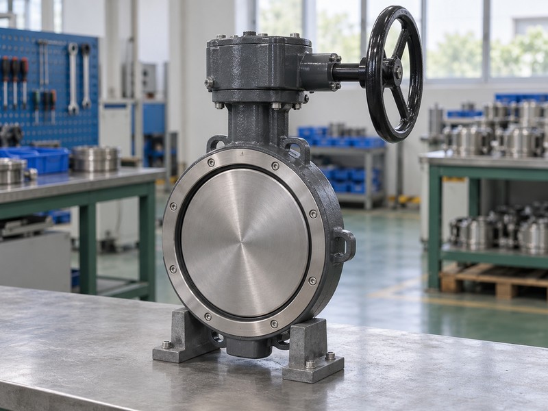
Review the complete installed envelope. Retain drive-fit and mounting definitions, operator mass or reaction assumptions and access for maintenance, enclosure opening and any supplied override. Override behavior, interlocks and permitted operating conditions follow selected instructions rather than a universal handwheel rule. The static manual installation image illustrates external layout only; it cannot prove electric-package fit, override behavior or powered operating performance.
- Check coupling engagement, alignment and mounting loads.
- Review enclosure and maintenance access in the actual location.
- Retain instructions for any supplied manual override.
Key takeaway: Review mounting and access against the actual electric package rather than a manual-valve envelope.
| Check | What you should confirm |
|---|---|
| Drive fit | Selected interfaces preserve alignment and usable engagement |
| Mounting | Bracket and body support the accepted operator arrangement |
| Access | Maintenance and supplied override functions have required space |
9. What environment suits an electric double offset butterfly valve?
The environment for an electric double offset butterfly valve affects both its valve materials and electric operator. Separate process-fluid temperature from actuator ambient conditions, moisture and external corrosion exposure. The selected enclosure and any special-service qualifications must match the actual installation and supplied accessories.
How should process heat and enclosure protection be reviewed?
Describe actual exposure conditions. State ambient range, water or dust exposure, corrosion conditions and any required hazardous-location basis, then request selected equipment confirmation. Review process heat and mounting arrangements where they affect actuator conditions without assuming the valve’s temperature limit also rates the operator. A generic manual-valve exterior proves neither electrical enclosure protection nor thermal suitability or approval for the proposed electric package.
- Define process and actuator ambient conditions separately.
- Describe actual moisture, dust and corrosion exposure.
- Check selected enclosure and accessory qualification coverage.
Key takeaway: Accept environmental suitability for the complete package using separate valve and electric-operator limits.
| Check | What you should confirm |
|---|---|
| Process | Valve configuration covers actual medium and temperature |
| Operator | Selected ambient and enclosure limits suit the location |
| Qualification | Required special-service coverage matches supplied equipment |
10. What accepts an electric double offset butterfly valve?
Acceptance of an electric double offset butterfly valve should connect its selected valve duty, actuator sizing and required functions with witnessed package evidence. Agree which mechanical movements, controls, feedback and defined failure cases require verification. Identify the responsible parties and acceptance records before testing or handover.
What must the witnessed package record retain?
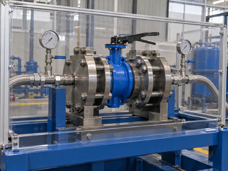
Verify the identified package. Retain the valve duty and torque basis, actuator output and supply data, mounting definition, control schedule and agreed results against the supplied identities. The Bray Series 70 electric actuator manual distinguishes travel switching and options for torque protection or battery backup; its mechanical stops protect manual overtravel rather than stopping the electric motor. A hydraulic test fixture cannot prove powered movement, command response, feedback integrity or the accepted electric-package failure behavior.
- Link sizing and interface records with actual supplied identities.
- Record agreed mechanical and functional observations under authorized procedures.
- Retain witnessed results and accepted technical exceptions at handover.
Key takeaway: Accept the package through connected sizing records and agreed functional evidence for its actual supplied configuration.
| Check | What you should confirm |
|---|---|
| Mechanical | Selected demand, output and drive limits remain documented |
| Functions | Required controls, feedback and failure cases are verified |
| Handover | Witnessed records match the accepted supplied package |
Send RUITO the identified valve construction, actual differential and temperature cases, torque requirements, available electrical supply and required operating functions. We can review the application and proposed assembly information and identify outstanding package questions. Contact us before approving an electric operator or assuming that separate configurations form a verified package.
FAQ
Q1: Can I size the electric actuator by valve diameter alone?
No. Use actual seating, unseating, movement and relevant fluid-torque demands for the selected seat, differential, medium and temperature.
Q2: Does a larger actuator automatically make the package suitable?
No. Adequate available output must also respect shaft, coupling, bracket and other connected-part limits.
Q3: Will every electric valve move to a safe position after power loss?
No. Specify required failure behavior for each event and verify that the selected equipment provides the documented means of achieving it.
Q4: Does actuator feedback prove valve sealing?
No. A position or status output has its own documented meaning. Mechanical integrity and hydraulic sealing require appropriate separate evidence.
Q5: Can a manual installation picture prove the electric package will fit?
No. Review the actual actuator envelope, coupling engagement, mounting loads, enclosure clearance and any supplied override access.