
Fix selection mistakes in a pneumatic double offset butterfly valve package by comparing actual valve demand with actuator output at the available air supply. Define commanded operation and each required energy-loss response separately. Accept the identified valve, operator, mounting and controls as one documented package before treating a pneumatic label as a sizing result.
An actuator can appear suitable at the quoted supply pressure while the valve needs more torque at a different part of travel or under the actual closing differential. A spring-return label can also leave its intended return direction undefined. Resolve demand, moving supply and required states before the package reaches assembly or commissioning.
1. What defines a pneumatic double offset butterfly valve?
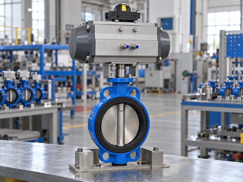
A pneumatic double offset butterfly valve combines an identified double-offset valve with a selected pneumatic rotary operating arrangement. Define body, seat, operator construction and supplied controls together. The actual quarter-turn actuator or documented conversion mechanism must produce the valve-shaft rotation required by the selected assembly.
What should the package definition make explicit?
Identify the complete arrangement. Request valve and actuator models, component list, assembly drawing and selected manuals. Linear piston movement needs its actual conversion mechanism and output data to define delivered rotary torque. Confirm body connection and offset geometry as one requested configuration without joining separate product-range specifications.
- Identify the actual valve, rotary operator and supplied accessories.
- Request the assembled configuration and applicable manuals.
- Confirm the requested body and offset combination independently.
Key takeaway: Define one selected pneumatic package before evaluating its torque or required operating states.
| Check | What you should confirm |
|---|---|
| Valve | Selected body, seat and geometry describe one configuration |
| Operator | Actual mechanism provides the required rotary output |
| Package | Assembly documents identify supplied controls and interfaces |
2. What torque fits a pneumatic double offset butterfly valve?
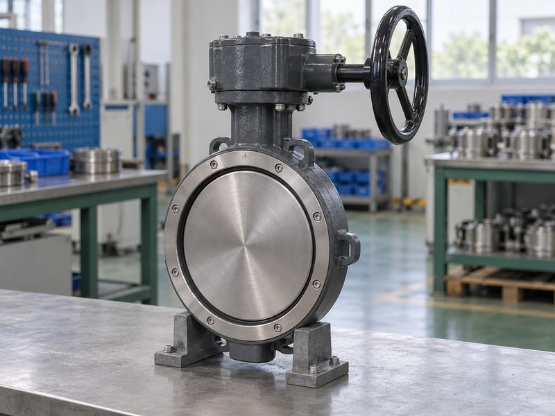
The torque required by a pneumatic double offset butterfly valve follows its actual seat, size, differential pressure, temperature and service. Review seating, unseating, running and relevant fluid torque for the required direction. Cam-like geometry cannot supply a universal torque reduction or make one catalogue demand value sufficient for every operating state.
What belongs in the valve-demand schedule?
Request the actual demand basis. The Keystone K-LOK technical sheet distinguishes torque by size, seat and shutoff conditions for its identified family. Retain actual valve demand across required travel and service states. Define any required return duty and the project or manufacturer basis for selection allowances.
- Identify actual seat, service and closing differential.
- Request the relevant operating-torque schedule or profile.
- Record the basis for required return duty and sizing allowance.
Key takeaway: Size from the selected valve’s demand across required conditions instead of a generic offset claim.
| Check | What you should confirm |
|---|---|
| Service | Demand matches the actual fluid, temperature and differential |
| Movement | Required seating, unseating and running duties are defined |
| Basis | Direction and any applied allowance have documented support |
3. What air feeds a pneumatic double offset butterfly valve?
The air available to a pneumatic double offset butterfly valve must be defined at the actuator during required movement. A regulator setting or upstream static pressure cannot establish the minimum pressure available while air flows. Review the actual supply path and accessory demand against the selected actuator and operating requirements.
Which air-path conditions belong in the sizing record?
Define the moving supply condition. Review the specified regulator, accessories, tubing, fittings and other restrictions through the air-supply assessment. Record minimum actuator-side pressure during required movement, with air quality and consumption checked against selected documents. Supply losses can change output, so the sizing record must state its actual pressure reference.
- Distinguish static upstream pressure from available moving supply.
- Review the specified air path and accessory restrictions.
- Record the actuator-side pressure reference and required supply conditions.
Key takeaway: Use the minimum actual actuator supply during movement when evaluating the selected output data.
| Check | What you should confirm |
|---|---|
| Reference | Sizing states where available pressure is defined |
| Flowing supply | Minimum pressure covers the required movement condition |
| Air path | Selected restrictions and supply capacity have a reviewed basis |
4. What output fits a pneumatic double offset butterfly valve?
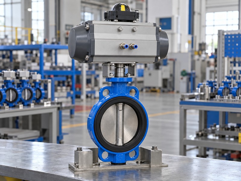
The output fitting a pneumatic double offset butterfly valve must cover required valve demand throughout the applicable stroke. Double-acting and spring-return arrangements need their selected output data at the actual supply and configuration. Spring-return review must include both the air-powered movement and available spring output in its required return direction.
Why should the reviewer compare more than one output point?
Compare the selected output profiles. The Bray Series 92/93 manual distinguishes double-acting, spring-return and return-direction configurations for its rotary actuator family. Request actual air and spring output data at relevant travel positions for the supplied arrangement. A single maximum torque cannot establish adequate seating or return output elsewhere in the stroke.
- Use actual actuator construction and output records.
- Compare required travel positions and movement directions.
- Review air-powered and spring-powered duties where applicable.
Key takeaway: Compare demand with the applicable output profile rather than one attractive catalogue torque value.
| Check | What you should confirm |
|---|---|
| Double acting | Powered output covers required duty in each direction |
| Spring return | Air and spring outputs suit the actual configured directions |
| Stroke | Relevant output across travel meets the selected demand |
5. What limits a pneumatic double offset butterfly valve drive?
The drive of a pneumatic double offset butterfly valve remains limited by permitted stem, coupling, mounting and actuator loads. Adequate movement torque does not establish acceptable maximum applied torque. Review the selected package’s possible output within its permitted supply and spring configuration against the valve and drive-component limits.
How should capacity and strength be compared?
Trace the complete drive limits. Retain required valve torque and allowable drive values with the selected output basis. Check shaft connection, coupling engagement and mounting through the assembly drawing. A larger actuator or shared mounting designation cannot replace that review; any limiting arrangement needs its own design and acceptance evidence.
- Separate required movement torque from allowable drive loads.
- Review actual operator output over its accepted operating range.
- Check shaft, coupling and mounting through the selected assembly.
Key takeaway: Approve both output sufficiency and component limits through the complete valve-operator drive.
| Check | What you should confirm |
|---|---|
| Demand | Required operating torque has an identified service basis |
| Output | Possible applied torque stays within the accepted package definition |
| Strength | Stem and other drive components remain within permitted limits |
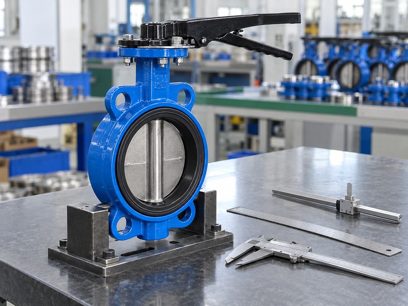
6. What if a pneumatic double offset butterfly valve loses air?
The response when a pneumatic double offset butterfly valve loses air depends on the selected actuator, controls, accessories and process loads. A spring-return label does not universally mean fail closed, and double acting does not guarantee position retention. Define the required response to air loss, electrical control loss and relevant combined loss separately.
When can position-retention accessories support the requirement?
Define each energy-loss condition. Record the intended physical position, available return capability and accepted control arrangement for each specified case. Air-lock or other retention devices need their own configuration, leakage and operating-condition review before they can support a position-retention claim. Trapped air or a normal command cannot establish the required loss response without the selected package definition and applicable verification.
- Specify air-loss and control-power-loss responses separately.
- Match spring direction and capability with the required return duty.
- Review any air-lock or retention claim within its actual conditions.
Key takeaway: Treat failure action as a defined package requirement rather than an automatic actuator-type guarantee.
| Check | What you should confirm |
|---|---|
| Condition | Each required energy-loss case has a defined response |
| Capability | Actual actuator and accessories support the intended movement or retention |
| Evidence | Selected arrangement and required verification support the claim |
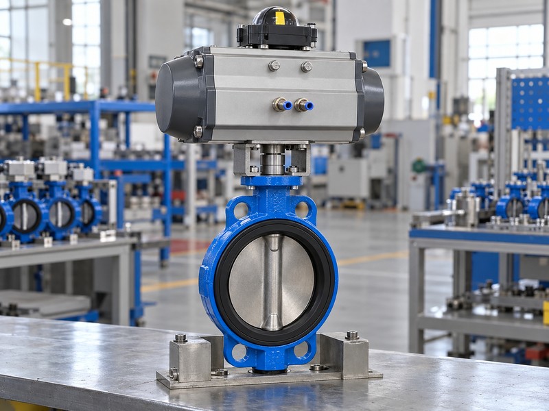
7. What mounts a pneumatic double offset butterfly valve?
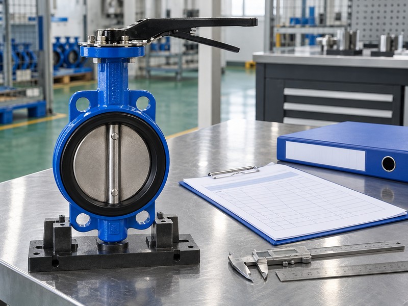
The mounting of a pneumatic double offset butterfly valve must match actual valve and actuator interfaces, drive engagement and accepted travel. Review the bracket, coupling and operator orientation through the selected assembly drawing. A matching bolt pattern cannot establish correct shaft engagement, permitted loads or suitable operating endpoints.
Which mechanical details need their own acceptance evidence?
Check the assembled interfaces. Compare mounting datums, drive profiles, usable engagement and clearances against the controlled design. Retain selected travel and stop instructions. Review operator support and access while keeping disc clearance and pipeline interfaces as separate installation checks governed by the actual valve documents.
- Review actual mounting, coupling and shaft definitions.
- Check engagement and clearance through common drawing references.
- Use selected instructions for travel and mechanical-stop requirements.
Key takeaway: Accept mechanical integration through the full assembly definition rather than the visible mounting pattern.
| Check | What you should confirm |
|---|---|
| Mounting | Actual bracket and mating interfaces match the selected design |
| Drive fit | Profile, engagement and clearances have accepted definitions |
| Travel | Operator and valve endpoints follow the selected instructions |
8. What controls a pneumatic double offset butterfly valve?
The controls for a pneumatic double offset butterfly valve depend on its specified on-off or modulating function and selected accessories. Record the command, required physical states and feedback definitions separately. A commanded position or external indication cannot establish actual valve closure or accepted leakage performance by itself.
How should command, feedback and loss response stay coordinated?
Define the accepted control functions. Identify solenoid valve, positioner and feedback devices only where included in the package. Link their documented functions with required valve positions and energy-loss cases. Feedback verifies its specified position relationship; sealing performance and loss behavior need separate acceptance evidence under approved project procedures.
- Identify actual on-off or modulating control requirements.
- Separate command, physical position and feedback references.
- Coordinate accessory behavior with the required energy-loss responses.
Key takeaway: Coordinate control intent with actual position and required failure action without equating those forms of evidence.
| Check | What you should confirm |
|---|---|
| Command | Selected controls receive the defined operating requirement |
| Feedback | Reported state has a documented physical reference |
| Response | Control and loss-state behavior agree with the accepted package |
9. What protects a pneumatic double offset butterfly valve?
A pneumatic double offset butterfly valve needs component limits suited to actual process and environmental conditions. Keep the valve’s pressure-temperature envelope separate from actuator ambient, air-quality and accessory requirements. Any manual override must also have an identified operating and restoration arrangement compatible with the required package behavior.
How should environment and manual override be reviewed?
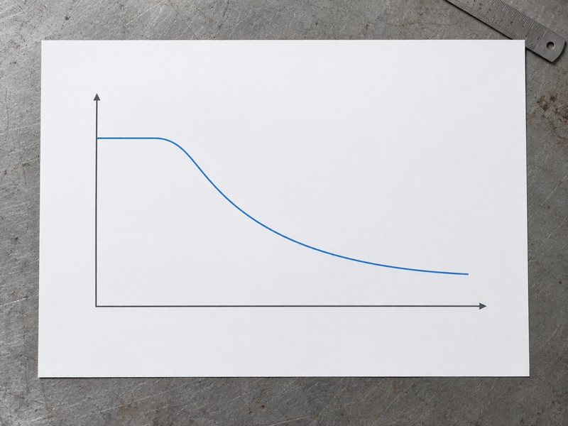
Review each component’s conditions. Check process temperature, exposure and component limitations through selected documents. The conceptual chart supplies no actual model rating or actuator air-pressure requirement. For an included override, retain permitted use and restoration instructions and its effect on automatic or energy-loss behavior; availability needs confirmation for the actual package.
- Review process and ambient conditions as separate component inputs.
- Match air quality and environmental exposure with selected requirements.
- Define any included override and its return-to-automatic conditions.
Key takeaway: Approve the package against actual component conditions and any included manual-override arrangement.
| Check | What you should confirm |
|---|---|
| Valve | Actual process conditions remain within selected rated limits |
| Operator | Ambient and supply conditions meet its applicable requirements |
| Override | Permitted use and restoration preserve the accepted package definition |
10. What accepts a pneumatic double offset butterfly valve?
Acceptance of a pneumatic double offset butterfly valve requires the identified configuration, sizing basis and required functional results to agree. Retain the valve demand, actuator outputs, available supply conditions, mechanical interfaces and accepted state definitions. A factory stroke demonstration alone cannot establish every required installed operating or energy-loss condition.
What should the package verification record retain?
Link each required result. Use the approved project plan and selected manuals for authorized normal-operation, feedback and specified energy-loss verification. Record the actual conditions, required criteria, results and unresolved deviations with assembly identity. RUITO can review an identified request and available documents, with the actual body, offset and pneumatic configuration confirmed before any supply commitment.
- Retain the accepted valve, actuator and accessory configuration.
- Link required functional results with actual test conditions.
- Close deviations and configuration questions through assigned responsibilities.
Key takeaway: Accept the identified package through its documented sizing, state definitions and required verification evidence.
| Check | What you should confirm |
|---|---|
| Baseline | Actual assembly matches the accepted design and sizing records |
| Verification | Required operating and energy-loss results have defined criteria |
| Closure | Accepted deviations and unresolved work remain traceable |
Send RUITO your identified valve request, seat and differential requirements, available air conditions, required energy-loss states and existing interface drawings. We can review the proposed scope and clarify which actual configuration and supporting documents would be needed for evaluation. Contact us before accepting a pneumatic package whose sizing or required failure action remains undefined.
FAQ
Q1: Can I size the actuator from the regulator setting alone?
No. Use the defined minimum available pressure at the actuator during required movement, with the actual air path and selected output data.
Q2: What’s the best output data to request for spring return?
Request the selected air and spring outputs across relevant travel. Match both with valve demand and the configured return direction.
Q3: How do I know if spring return means fail closed?
Check the actual package definition. Spring arrangement, mounting, controls and return capability must support the required loss-state position.
Q4: Can I assume double acting holds position after air loss?
No. Position retention depends on the actual actuator, accessories, leakage and loads, with applicable verification supporting the required behavior.
Q5: How do I know whether a larger actuator is acceptable?
Check capacity and limits. Required output must suit valve demand without exceeding permitted stem, coupling, mounting or other drive-component loads.